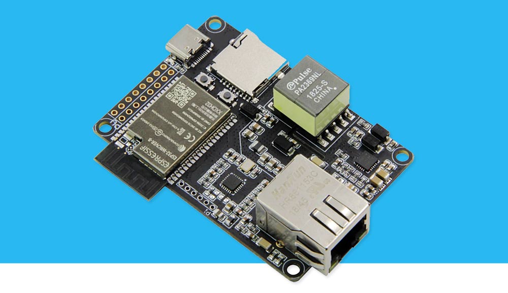
I caught sight of the LILYGO TTGO T-Internet-POE ESP32 LAN8270A board and of course I could not pass by such an interesting novelty: ESP32, LAN8270A, POE, SD card, Wi-Fi + Ethernet ... It was interesting to feel this work of a gloomy Chinese genius with my own hands and test it in real work, because TTX boards promised very interesting prospects for use in IoT, DIY, and in general in the field of "Wi-Fi + Ethernet and what you can imagine."
But, as always, the path from advertising brochures on the websites of sellers and manufacturers to launching the board and conducting tests on it turned out to be very difficult and thorny. Next, I bring to your attention a report on my fascinating research on this topic.
Stone in the garden LILYGO
According to my observations (many) manufacturers of "hardware" suffer from one generic disease - a complete lack of competence in marketing and, in general, an elementary understanding of what their products are doing for people.
A good example here is LILYGO TTGO T-Internet-POE ESP32 LAN8270A (hereinafter we will call this board T-Internet-POE for brevity). The manufacturer made an interesting board, but ... did nothing else:
- no normal controller pinout
- no circuit diagram
- there is no sane description of the use of the board and typical patterns of its use
- there are no technical explanations for the operation of individual components of the board
- no code examples (there is 1 (!) sketch for "fuck off, boy, don't bother work")
- no website with documentation
- there is no forum with competent and motivated moderators
- there are no popular and motivating articles for those who are interested in this controller, but do not know (do not understand) where he could use it for his own purposes
- and there are still many things that should have been
In short, there is nothing at all and everyone who dares to buy T-Internet-POE must be an impeccable DIY warrior, otherwise he has no chance to survive this battle with LILYGO. Are there many of us like that?
And how, with this approach to business, do they even manage to sell something? And how much would their sales increase if they put the soldering iron aside for a moment and remembered their customers?
The questions are rhetorical, but one way or another, further I will have to do all the work for the technical and marketing departments of LILYGO.
What's the trick?
In simple terms, on this board we managed to more or less successfully combine ESP32 (Wi-Fi), Ethernet, POE in one device, and add a cherry on top of this cake in the form of a microSD card reader. From just one combination of these components, many interesting options for using this board immediately follow:
- work via Wi-Fi with a backup in the form of an Ethernet channel
- work over Ethernet with a backup in the form of a Wi-Fi connection
- service of both Wi-Fi and Ethernet links
- router between Wi-Fi and Ethernet in both directions
- web server for two interfaces
- different web servers on different interfaces
- power supply of the (remote) controller via POE
And many other interesting options (by the way, do not forget that in addition to the network component itself, the board has GPIO outputs and can be used for its intended purpose, that is, as an IoT controller).
As you can see, the scope of application of this board in IoT and DIY is limited only by your imagination and your needs, and in general T-Internet-POE looks very promising as a device.
Next, let's try to figure out how to cope with all this splendor, which, given the almost complete lack of information on the board, is not such an easy task.
Specifications
We will not provide here a complete list of all the technical characteristics of the board - that’s with what, and there are no problems with that on the websites of sellers and manufacturers (the problem is that there is nothing else besides these characteristics). Here is just a list of key board elements:
- ESP32-WROOM (4MB)
- LAN8720A (Ethernet PHY)
- POE 802.3af
- microSD card reader
- 12 GPIO pins for external connections
What does this configuration tell us offhand? That when using this board as a web server, files can be stored both on a microSD memory card and in the internal memory of the ESP32 module (or both there and there at once).
At the same time, 12 free GPIOs produce an ambiguous impression - on the one hand, this is already "something" and much better than on the ESP8266, and on the other hand, after projects on the Mega 2560 with its dozens of GPIOs, 12 pins look very, very modest and severely limit development opportunities - here you will either need to invent some kind of port extenders, or do tandem assemblies with other controllers.
Controller options
Upon closer inspection, it turns out that under the same name there are two different controllers - one on the ESP32-WROOM, and the second on the ESP32-WROVER-B, which you can't immediately see - the boards look almost the same and you can play the game "find 10 differences" ...

I got the controller on the ESP32-WROOM, so the further narration will refer to it.
Programmer
LILYGO engineers are so far removed from their users that their decisions are not always easy to understand. These solutions include the creation of a separate programmer board on the CP2104 chip for the T-Internet-POE controller.
What for? Why do you need a separate programmer, when this node could be integrated on the controller board itself, or simply use standard USB-TTL adapters (as all other hardware manufacturers do)? The answer, apparently, only the LILYGO developers know (but let's forgive them this little creative).

But not only did the LILYGO developers do an incomprehensible thing, they also managed to make it crooked:
- firstly, they used pins beloved by the people with a pitch of 2.0 mm
- secondly, they provided for the installation of the connector on the reverse (!) side of the board
(For developers of such a solution, I would recommend sometimes distracted from work and take time to rest.)
The result is some kind of strange monster. And everything would be fine if the problem was limited only to the aesthetic component, but here more serious problems emerge:
- if the board is installed and fastened in its normal position, then the programmer pins are at the bottom of the board and it is impossible to connect to them without dismantling the controller;
- if you work with the board without fastening, then the connectors with a pitch of 2.0 do not provide adequate rigidity and the whole structure threatens to fall apart at any moment and close everything around.
As a leveling-off for this jamb of developers, we can recommend soldering a line of pins on the top side of the board and making (or buying, if sold) a 6-pin 2.0 mm flexible adapter.
Pinout
To begin with, we present the original version of the pinout (cultivated as much as possible). For those "who are in the know" there is enough information, the rest will understand little from this "Chinese literacy".

Let's try to translate this into Russian and generally figure out what happens there with the pinout of elements and the distribution of controller resources.
In total, ESP32 has 40 pins (D0 – D39), of which 14 pins
D6 – D11, D20, D24, D28-D31, D37, D38
we exclude from consideration as practically unused (for various reasons, a detailed analysis of the purpose of these pins is beyond the scope of of this article). Remain:
Ethernet connection pins of the LAN8720A chip
D18 - ETH_MDIO_PIN
D19 - ETH_TX_D0
D21 - ETH_TX_EN
D22 - ETH_TX_D1
D23 - ETH_MDC_PIN
D25 - ETH_RX_D0
D26 - ETH_RX_D1
D27 - ETH_RX_CRS
are installed in the LAN chip, while D20A and D23 are installed in the LAN standard
Since the manufacturer hesitated to provide a schematic diagram of the controller, I can only give here a similar typical Ethernet physics connection diagram on LAN8720A.
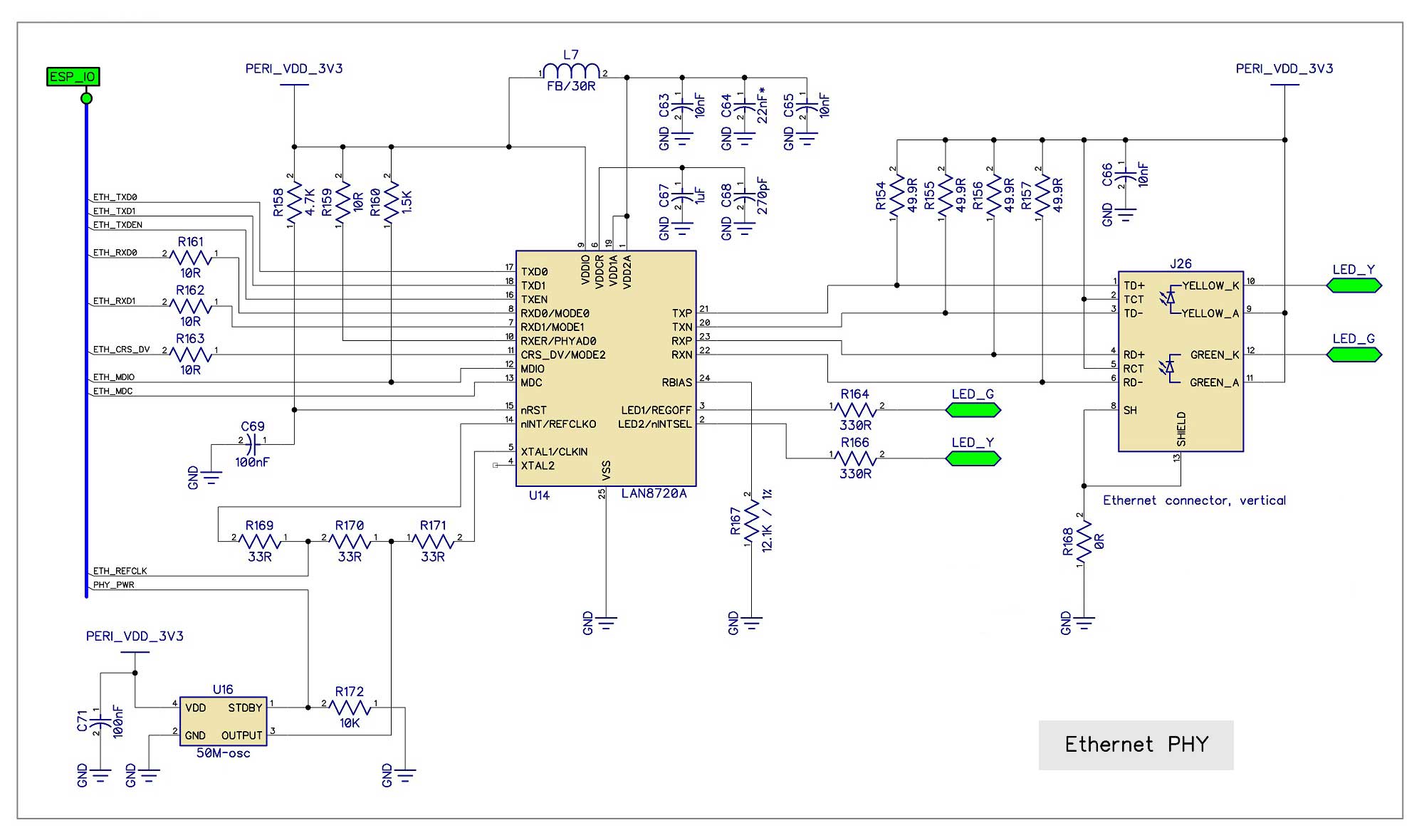
The LAN8720A also has a clock pin, which is connected to D17 on the T-Internet-POE board (also selected in the sketch):
D17 - ETH_CLOCK
and reset pin
D5 - NRST
microSD card reader
microSD card reader is connected to HSPI:
D2 - SD_MISO
D12 - SD_CS
D14 - SD_SCLK
D15 - SD_MOSI
and in case of its use "takes" pins D2, D14, D15 free for external connections and brought to the board. The question "which is more profitable - to use a card reader and lose 3 of 12 free pins, or keep 3 extra GPIOs and abandon the card reader" is akin to the question "which is better: an elephant or a horse?" and you have to answer it every time you use the T-Internet-POE card.
Other pins
We still have pins D0 (ETH_CLOCK, not used in this capacity) and D1 (TX0) and D3 (RX0).
Free pins
Now let's move on to the most interesting part - the description of free pins brought to the controller board.
The first is the group D34, D35, D36, D39, which works only for the entrance. Better, of course, to the input than nothing at all, but with such a shortage of GPIOs, it would be much better if these four pins were full-fledged GPIOs.
And then 8 full-fledged GPIOs that you can use in your projects. Here you need to remember that although these pins are full-fledged GPIOs, some of them work in a very peculiar way (for example, they change the potential at the start of the controller, etc.). Therefore, before you connect something to them, you need to specifically find out and clarify these points.
D2 (SD_MISO)
D4
D12
D14 (SD_SCLK)
D15 (SD_MOSI)
D16
D32
D33
As they say, here's to you, my young friend of programming and microcontrollers, 8 GPIOs and don't deny yourself anything.
POE
Here we need to say a few more words about POE support, since this is one of the advantages of this board and one of its "chips" and for many it will be the reason why they want to buy and use it.
It implements full support for the POE 802.3af standard with isolation and power management on the SI3404 chip.
I am not very interested in remote powering of the controller, so I have not tested this aspect of the T-Internet-POE performance, but, apparently, there are no problems with POE.
Software support
As you yourself understand, you can work with T-Internet-POE using any software environment that knows about this hardware, including the native SDK (and this is probably the most correct option), but we will try to find out what can be squeezed out of this pieces of iron using the Arduino IDE.
As a software environment for experiments, we used Arduino IDE version 1.8.5 and ESP32-Arduino version 1.0.5 (the latest build at the time of this writing).
I will not describe the very process of installing ESP32 support in the Arduino IDE, because a huge amount of materials on the Internet are devoted to this issue, describing this process in all the nuances.
I will mention only one point here: plus everything that this controller does not have, it does not yet have native support in the ESP32-Arduino version 1.0.5. Therefore, “ESP32 DEV Module” was selected as a controller in the board manager with the following settings:
Flash Mode: DIO
Flash Size: 4MB (32 Mb)
Partition Scheme: 4MB (1.2MB / 1.5MB)
Standard sketch
Below is a sketch that pleased us with the board manufacturer . There is nothing special to comment on, it just initializes the Ethernet interface and sends requests to the server on the Internet.
Full sketch code from the board manufacturer
/*
    This sketch shows how to configure different external or internal clock sources for the Ethernet PHY
*/

#include <ETH.h>
#include <SPI.h>
#include <SD.h>

#define SD_MISO         2
#define SD_MOSI         15
#define SD_SCLK         14
#define SD_CS           13
/*
   * ETH_CLOCK_GPIO0_IN   - default: external clock from crystal oscillator
   * ETH_CLOCK_GPIO0_OUT  - 50MHz clock from internal APLL output on GPIO0 - possibly an inverter is needed for LAN8720
   * ETH_CLOCK_GPIO16_OUT - 50MHz clock from internal APLL output on GPIO16 - possibly an inverter is needed for LAN8720
   * ETH_CLOCK_GPIO17_OUT - 50MHz clock from internal APLL inverted output on GPIO17 - tested with LAN8720
*/
// #define ETH_CLK_MODE    ETH_CLOCK_GPIO0_OUT          // Version with PSRAM
#define ETH_CLK_MODE    ETH_CLOCK_GPIO17_OUT            // Version with not PSRAM

// Pin# of the enable signal for the external crystal oscillator (-1 to disable for internal APLL source)
#define ETH_POWER_PIN   -1

// Type of the Ethernet PHY (LAN8720 or TLK110)
#define ETH_TYPE        ETH_PHY_LAN8720

// I²C-address of Ethernet PHY (0 or 1 for LAN8720, 31 for TLK110)
#define ETH_ADDR        0

// Pin# of the I²C clock signal for the Ethernet PHY
#define ETH_MDC_PIN     23

// Pin# of the I²C IO signal for the Ethernet PHY
#define ETH_MDIO_PIN    18

#define NRST            5
static bool eth_connected = false;

void WiFiEvent(WiFiEvent_t event)
{
    switch (event) {
    case SYSTEM_EVENT_ETH_START:
        Serial.println("ETH Started");
        //set eth hostname here
        ETH.setHostname("esp32-ethernet");
        break;
    case SYSTEM_EVENT_ETH_CONNECTED:
        Serial.println("ETH Connected");
        break;
    case SYSTEM_EVENT_ETH_GOT_IP:
        Serial.print("ETH MAC: ");
        Serial.print(ETH.macAddress());
        Serial.print(", IPv4: ");
        Serial.print(ETH.localIP());
        if (ETH.fullDuplex()) {
            Serial.print(", FULL_DUPLEX");
        }
        Serial.print(", ");
        Serial.print(ETH.linkSpeed());
        Serial.println("Mbps");
        eth_connected = true;
        break;
    case SYSTEM_EVENT_ETH_DISCONNECTED:
        Serial.println("ETH Disconnected");
        eth_connected = false;
        break;
    case SYSTEM_EVENT_ETH_STOP:
        Serial.println("ETH Stopped");
        eth_connected = false;
        break;
    default:
        break;
    }
}

void testClient(const char *host, uint16_t port)
{
    Serial.print("\nconnecting to ");
    Serial.println(host);

    WiFiClient client;
    if (!client.connect(host, port)) {
        Serial.println("connection failed");
        return;
    }
    client.printf("GET / HTTP/1.1\r\nHost: %s\r\n\r\n", host);
    while (client.connected() && !client.available());
    while (client.available()) {
        Serial.write(client.read());
    }

    Serial.println("closing connection\n");
    client.stop();
}

void setup()
{
    Serial.begin(115200);

    WiFi.onEvent(WiFiEvent);

    SPI.begin(SD_SCLK, SD_MISO, SD_MOSI, SD_CS);
    if (!SD.begin(SD_CS)) {
        Serial.println("SDCard MOUNT FAIL");
    } else {
        uint32_t cardSize = SD.cardSize() / (1024 * 1024);
        String str = "SDCard Size: " + String(cardSize) + "MB";
        Serial.println(str);
    }

    pinMode(NRST, OUTPUT);
    digitalWrite(NRST, 0);
    delay(200);
    digitalWrite(NRST, 1);
    delay(200);
    digitalWrite(NRST, 0);
    delay(200);
    digitalWrite(NRST, 1);


    ETH.begin(ETH_ADDR, ETH_POWER_PIN, ETH_MDC_PIN, ETH_MDIO_PIN, ETH_TYPE, ETH_CLK_MODE);
}


void loop()
{
    if (eth_connected) {
        testClient("baidu.com", 80);
    }
    delay(10000);
}
When I saw this sketch for the first time, I wondered: "What did the manufacturer want to say with this?" The only purpose of this sketch is to show that this technology works in principle. This is certainly good, but what next? What to do with all this without having any documentation, or examples, or a sane response from the manufacturer?
The campaign turns out that the answer from LILYGO is to learn programming and create software on your own (or look for ready-made firmware, although this is not sports).
Interfaces and ping
For network professionals (and those who have joined them), I will say a few words about the speed of work over Wi-Fi and Ethernet interfaces and their responsiveness. The tests were carried out in an unloaded gigabit network, the noise level of the Wi-Fi range was not specifically controlled.
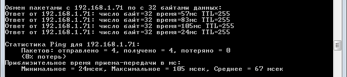
The first screenshot is a ping of the controller via the Wi-Fi interface. Minimum 24 ms, maximum 105 ms, average 67 ms.
The second is to ping the controller via the Ethernet interface. Minimum 0 ms, maximum 9 ms, average 2 ms.

As you can see, ping over wired Ethernet is dramatically lower than over Wi-Fi (which is expected). How good or bad these numbers are, I leave to the readers to judge for themselves, they are quite suitable for me for my purposes.
Testing
It's not serious to test a system like T-Internet-POE on sketches similar to the one suggested by the manufacturer, so a specialized version of AMS, adapted specifically for this board, was used to test the controller. Considering that this is a server that uses full-fledged HTML, CSS, Javascript, Ajax, graphic files and libraries, the successful operation of such a server on T-Internet-POE will indicate a properly designed hardware and the possibility of using it in real projects.
Note: testing was performed on an internal, non-public version of AMS for T-Internet-POE. The publication and distribution of this version is not planned, perhaps it will be done later, after appropriate improvements.
Test 1. Run AMS server on T-Internet-POE
Launching AMS on a new controller with a new chip and a new network interface is not a trivial task, but nevertheless, with the right approach and understanding of what you are doing, everything becomes possible.
Jamb number 1
In the process of this work, the "shoals" of the T-Internet-POE controller began to come out and the first thing that was revealed was that the controller refuses to flash when a microSD memory card is inserted. Nothing helps - neither replacing the USB port, nor powering from a separate unit, nor pressing buttons, nor replacing the card - the controller stubbornly refuses to flash with a memory card inserted.
It is difficult to say a glitch of a specific instance or a generic defect of all T-Internet-POE controllers (having one instance at our disposal), we can only state that the problem is 100% repeatable and reproducible.
What does this mean for us? In practical terms, this means that the T-Internet-POE controller actually does not have a card reader - a card reader that blocks the controller's firmware is not a card reader, but a bug.
What to do? All that remains is to use the 1.5 MB SPIFFS available on the ESP32 module. Yes, this is not very much, but in principle, 1.5 MB of memory for an IoT device is more or less acceptable in most cases.
Jamb number 2
Ok, we abandoned the card reader, now we need to make friends with SPIFFS. It seems that the task is simple and even familiar, but here we are in for an ambush: for some reason, the ESP32FS utility refuses to work normally on this controller (in this configuration). Moving files to the ESP32 module memory results in a subsequent error mounting the SPIFFS disk.
Hmmm ... If it is impossible to transfer files (servers) to a SPIFFS disk normally, there is only one way - initialization of the interface via a Serial connection, and then transferring files to a SPIFFS disk via the web interface. The method, of course, is not very convenient, but it does not affect the final result in any way - the server files were successfully transferred to the SPIFFS disk.
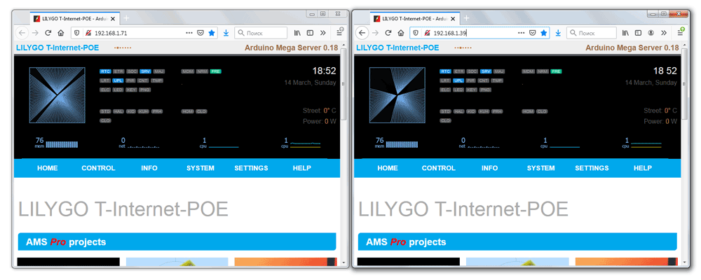
I omit the description of the process of adapting the code for the new controller, since this would require compiling an anthology like a complete collection of works by V.I.Lenin and immediately proceed to demonstrating the fact of the successful operation of the AMS server on the T-Internet-POE (and therefore the operability of the T -Internet-POE).
Loading the page via Wi-Fi interface.

Loading the page via Ethernet interface.
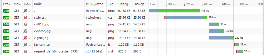
The gain in speed is about 4 times, naturally, in favor of Ethernet. It should also be borne in mind that we are talking about unoptimized code and after carrying out the appropriate work, the results should improve significantly.

Server operation via Ethernet interface on LILYGO TTGO T-Internet-POE ESP32 LAN8270A.
Test 2. Working on two interfaces
This is where I have to do a little bit of mythbreaker work. There are persistent rumors on the Internet that the simultaneous operation of Wi-Fi and Ethernet on a bundle of ESP32 and LAN8270A is impossible. This is not so - the AMS server works great on two interfaces at the same time and perfectly serves requests over Wi-Fi and Ethernet. There are no problems with ESP32 freezes or reboots.
This is already an interesting result, which opens up tempting prospects: since we have our own server, we can manage the service of the interfaces in any way, for example, over Wi-Fi to serve some sites with one content, and over Ethernet - other sites with other content. Figuratively speaking, to give a site with culinary recipes to a grandmother via Ethernet, and a site with selected articles from TSB to a grandson via Wi-Fi.
Test 3. Ban on one of the interfaces
Now let's try to put into practice the idea of serving different interfaces by the web server. As an example, let's try to implement a denial of service for connections over one of the interfaces (Ethernet).
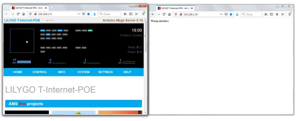
A client connected to our controller via an Ethernet interface received a denial of service.
Interface redundancy
The very idea of interface reservation is on the surface and asks for implementation. There are many similar scenarios, for example, you have an IoT controller that is connected to a local network via Ethernet. In the event of an emergency, if the wired link is lost, the controller automatically connects to the backup wireless router and continues its work.
Network routing
With two working network interfaces at your disposal, you can route packets in the network as you like. No one bothers to add data routing via nRF24 or LoRa or via any other wireless network to the Wi-Fi and Ethernet routing scheme. Thus, you can make any router for your IoT system.
Well, and as noted above, there are many more interesting use cases for a controller with two network interfaces.
Outcomes
Now let's summarize this little research: in general, despite some jambs and childhood illnesses, I liked the LILYGO TTGO T-Internet-POE ESP32 LAN8270A controller - it's an excellent tool for building IoT systems, especially if you have the appropriate qualifications and are not without imagination and a creative approach to your work.
Pros and cons of LILYGO TTGO T-Internet-POE ESP32 LAN8270A.
Pros:
- It works!
- Complete Integrated Wi-Fi + Ethernet + POE + GPIO Solution
- Good work without freezes and reboots (no problems were identified during testing)
- Possibility of simultaneous work on two interfaces
Minuses:
- Total lack of documentation, examples and explanations
- Relatively high entry threshold
- Childhood illnesses and minor shoals in implementation