It was back in 2015. Oculus DK2 virtual reality glasses just appeared on sale, the VR games market was rapidly gaining popularity.
The player's opportunities in such games were limited. Only 6 degrees of freedom of head movements were monitored - rotation (with an inertial in glasses) and movement in a small volume in the visibility zone of an infrared camera fixed on the monitor. The game process consisted of sitting on a chair with a gamepad in hands, rotating the head in different directions and fighting nausea.
It didn't sound very cool, but I saw this as an opportunity to do something interesting, using my experience in electronics development and a thirst for new projects. How could this system be improved?
Of course, get rid of the gamepad, the wires, give the player the opportunity to move freely in space, see their hands and feet, interact with the environment, other players and real interactive objects.
I saw it like this:
- We take several players, put on VR glasses, a laptop and sensors on their arms, legs and torso.
- We take a room consisting of several rooms, corridors, doors, equip it with a tracking system, hang sensors and magnetic locks on the doors, add several interactive objects and create a game in which the geometry of a virtual location exactly repeats the geometry of a real room.
- We create a game. The game is a multiplayer quest in which several players put on equipment and find themselves in a virtual world. In it, they see themselves, see each other, can walk around the location, open doors and jointly solve game problems.
I told this idea to my friend, who unexpectedly accepted it with great enthusiasm and offered to take over organizational issues. So we decided to muddle the startup.
To implement the declared functionality, it was necessary to create two main technologies:
- a suit consisting of sensors on the arms, legs and torso that tracks the position of the player's body parts
- a tracking system that tracks players and interactive objects in 3D space.
The development of the second technology will be discussed in this article. Maybe later I will write about the first one.
Tracking system.
Of course, we did not have the budget for all this, so we had to do everything from scrap materials. For the task of tracking players in space, I decided to use optical cameras and LED markers attached to VR glasses. I had no experience of such development, but I already heard something about OpenCV, Python, and thought that I could do it.
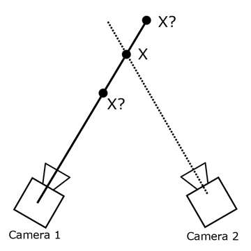
As conceived, if the system knows where the camera is located and how it is oriented, then by the position of the marker image on the frame, you can determine the straight line in 3D space on which this marker is located. The intersection of two such lines gives the final marker position.
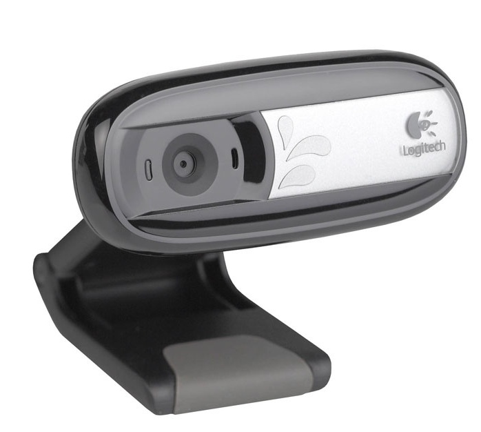
Accordingly, the cameras had to be fixed on the ceiling so that each point in space was viewed by at least two cameras (preferably more, to avoid obstructing the view by the bodies of the players). It took about 60 cameras to cover the supposed premises with an area of about 100 square meters. I chose the first available cheap usb webcams at that time.
These webcams need to be connected to something. Experiments have shown that when using usb extension cords (at least cheap ones), the cameras began to glitch. Therefore, I decided to divide the webcams into groups of 8 pieces and stick them into the system units mounted on the ceiling. There were just 10 usb ports on my home computer, so it's time to start developing a test bench.
The architecture I came up with is the following:
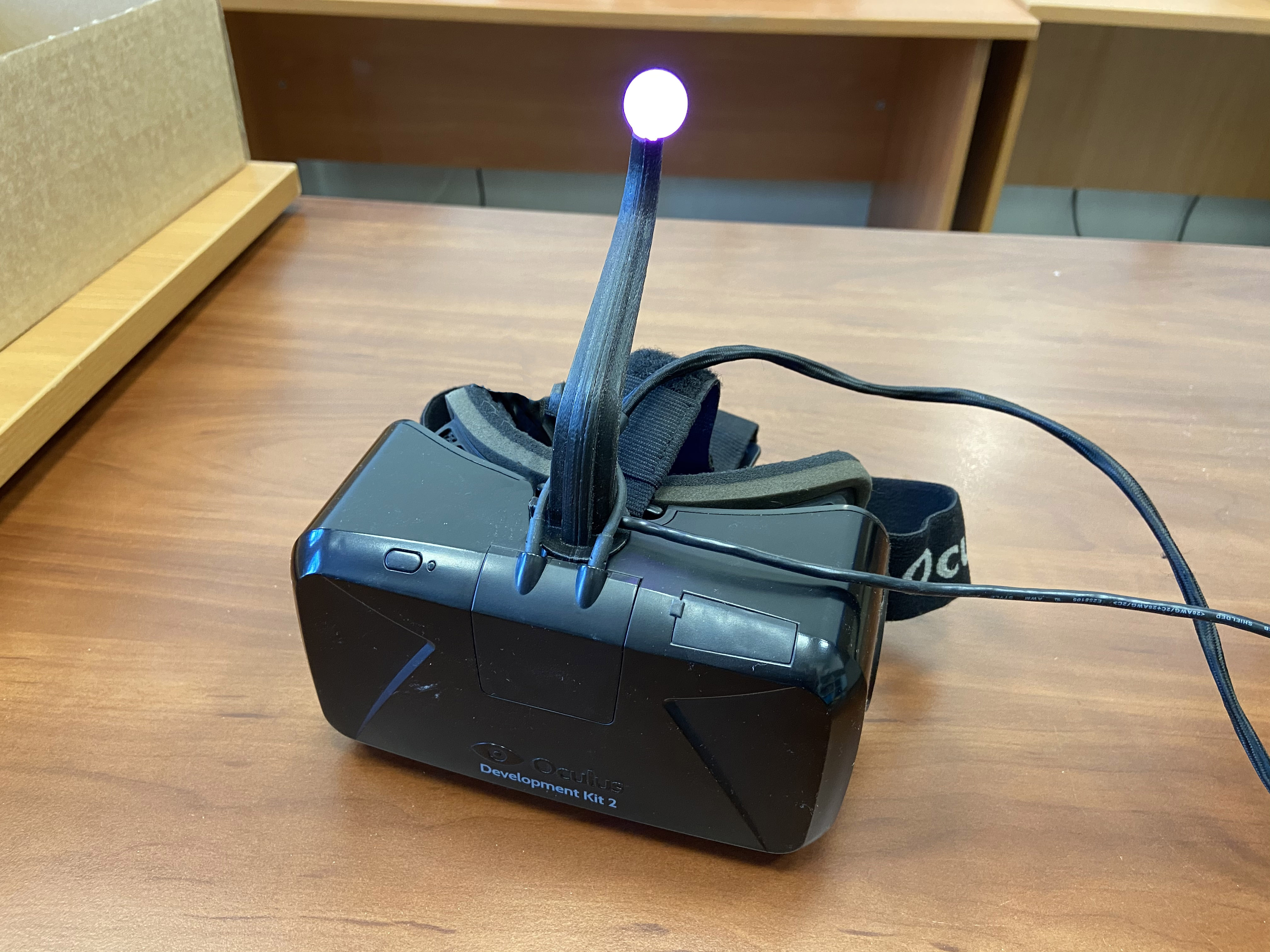
An acrylic frosted ball from a garland with an RGB LED glued inside is hung on each glasses. Several players were supposed to be in the game at the same time, so for identification I decided to separate them by color - R, G, B, RG, RB, GB, RB. This is how it looked:
The first task to be performed is to write a program for finding a ball on a frame.
Finding the ball on the frame
I had to look for the coordinates of the center of the ball and its color for identification in each frame that came from the camera. Sounds easy. I download OpenCV for Python, plug the camera into usb, write a script. To minimize the influence of unnecessary objects in the frame, I set the exposure and shutter speed on the camera to the very minimum, and the brightness of the LED is high to get bright spots on a dark background. In the first version, the algorithm was as follows:
- ( , , – ).
- .
- ( )
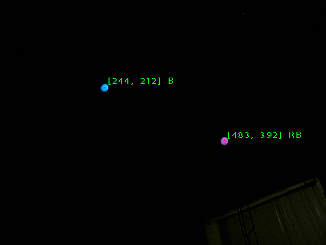
It seems to work, but there are nuances.
First, on a cheap camera, the matrix is quite noisy, which leads to constant fluctuations of the contours of binarized clusters and, accordingly, to jerking of the center. It is impossible for the players to twitch the picture in VR glasses, so this problem had to be solved. Attempts to use other types of adaptive binarization with different parameters did not give much effect.
Secondly, the resolution of the camera is only 640 * 480, so at some distance (not very large) the ball is visible as a couple of pixels in the frame and the edge search algorithm stops working normally.
I had to come up with a new algorithm. The following idea came to my mind:
- Convert the image to grayscale
- Gaussian blur – ,
- ,
This works much better, the coordinates of the center are stationary when the ball is stationary, and it works even at a great distance from the camera.
To make sure that all this will work with 8 cameras on one computer, you need to conduct a stress test.
Load test I
connect 8 cameras to my desktop, arrange them so that each one sees glowing dots and run a script where the described algorithm works in 8 independent processes (thanks to the Python multiprocessing library) and processes all threads at once.
And ... I immediately come across a fail. Camera images appear and disappear, framerate jumps from 0 to 100, a nightmare. The investigation showed that some of the usb ports on my computer are connected to the same bus through an internal hub, which is why the bus speed is divided between several ports and is no longer enough for the camera bitrate. Plugging the cameras into different ports of the computer in different combinations showed that I have only 4 independent usb buses. I had to find a motherboard with 8 buses, which was a rather difficult quest.
Spoiler
Intel B85, 10 usb . 10- , OpenCV, .. 8 (?)
I continue the load test. This time, all the cameras are connected and output normal streams, but I immediately come across the next problem - low fps. The processor is 100% loaded and only manages to process 8-10 frames per second from each of the eight webcams.
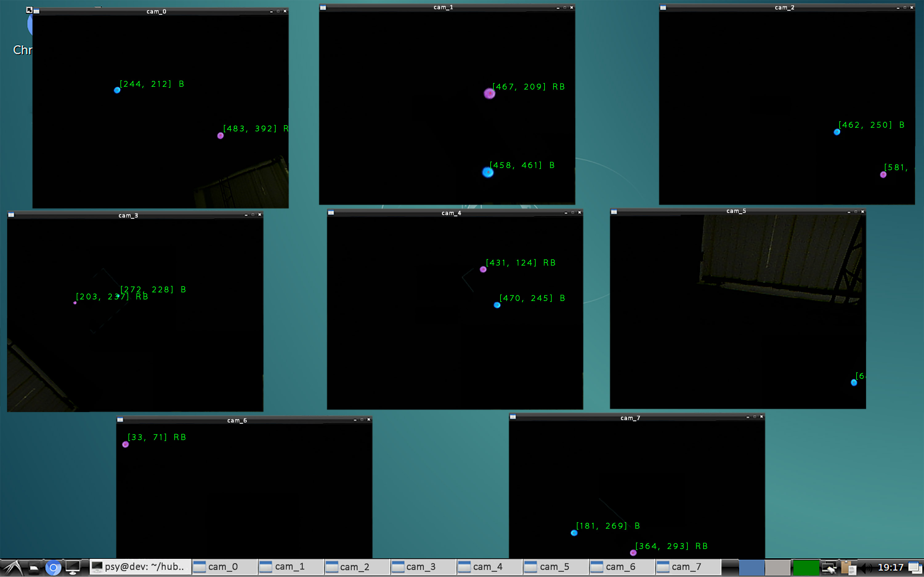
It looks like the code needs to be optimized. The bottleneck turned out to be Gaussian blur (it is not surprising, because you need to convolve with a 9 * 9 matrix for each pixel of the frame). Reducing the kernel did not save the situation. I had to look for another method for finding the centers of the spots on the frames.
The solution was suddenly found in the SimpleBlobDetector function built into OpenCV. She does exactly what I need and very quickly. The advantage is achieved due to the sequential binarization of the image with different thresholds and the search for contours. The result is a maximum 30 fps with a CPU load of less than 40%. Load test passed!
Color classification
The next task is to classify the marker by its color. The averaged color value over the spot pixels gives RGB components that are very unstable and vary greatly depending on the distance to the camera and the brightness of the LED. But there is a great solution: translation from RGB space with HSV (hue, saturation, value). In this representation, the pixel instead of "red", "blue", "green" is decomposed into the components "hue", "saturation", "brightness". In this case, saturation and brightness can simply be excluded and classified only by hue.

Technical details
, «» . , . , . «» .
:
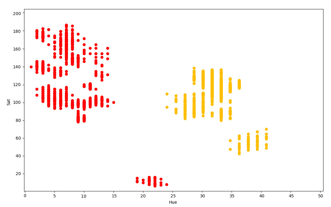
:
- (, R – )
- , , . «hue – saturation»
- . , .
- , , . . , , . .. , . , - , , .

And so, at the moment I have learned how to find and identify markers in frames from a large number of cameras. Now you can go to the next stage - tracking in space.
Tracking
I used a pinhole camera model in which all rays fall on the matrix through a point located at the focal length of the matrix.
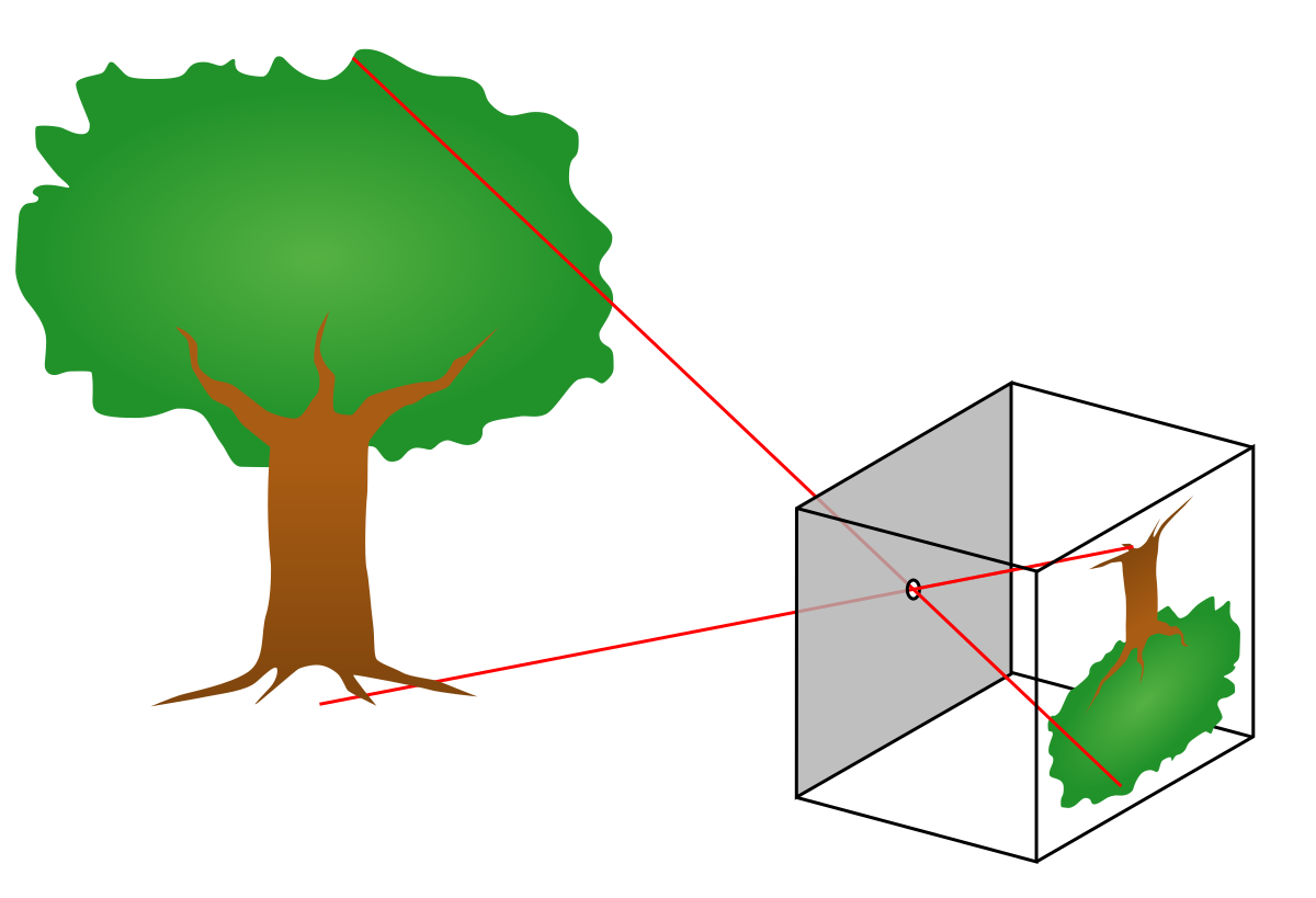
This model will transform the two-dimensional coordinates of a point on the frame into three-dimensional equations of a straight line in space.
To track the 3D coordinates of the marker, you need to get at least two intersecting lines in space from different cameras and find the point of their intersection. It is not difficult to see the marker with two cameras, but to build these lines, you need the system to know everything about the connected cameras: where they hang, at what angles, the focal length of each lens. The problem is that none of this is known. Calculation of the parameters requires some kind of calibration procedure.
Tracking Calibration
In the first version I decided to make tracking calibration as primitive as possible.
- I hang the first block of eight cameras on the ceiling, connect them to a system unit that hangs in the same place, direct the cameras so that they cover the maximum game volume.
- Using a laser level and rangefinder, I measure the XYZ coordinates of all cameras in a single coordinate system
- To calculate orientations and focal lengths of cameras, I measure the coordinates of special stickers. I hang up the stickers as follows:
- In the interface for displaying a picture from the camera, I draw two points. One in the center of the frame, another 200 pixels to the right of center
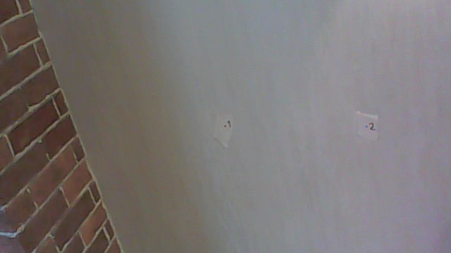
- If you look at the frame, these points fall somewhere on the wall, floor or any other object inside the room. I hang paper stickers in the appropriate places and draw dots on them with a marker
- I measure the XYZ coordinates of these points using the same level and rangefinder. In total, for a block of eight cameras, you need to measure the coordinates of the cameras themselves and two more points for each. Those. 24 triplets of coordinates. And there should be about ten such blocks. It turns out a long dreary work. But nothing, I'll make the calibration automated later.
- I start the calculation process based on the measured data
- In the interface for displaying a picture from the camera, I draw two points. One in the center of the frame, another 200 pixels to the right of center
There are two coordinate systems: one global, associated with the room, and the other local to each camera. In my algorithm, the result for each camera should be a 4 * 4 matrix, containing its location and orientation, allowing you to convert coordinates from local to global.
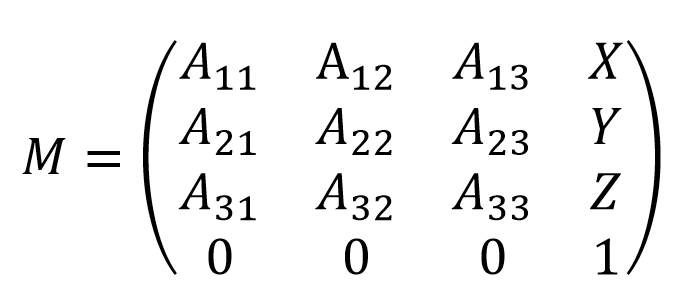
The idea is as follows:
- We take the original matrix with zero rotations and offset.
- , .
- , .
- , . , . . 200 . , .
- (, 200 ).
Surely this problem could be solved analytically, but for simplicity I used a numerical solution on gradient descent. It's not scary, because calculations will be performed once after cameras are installed.
To visualize the calibration results, I made a 2D interface with a map, on which the script draws the labels of the cameras and the directions in which they see the markers. Triangles represent camera orientations and viewing angles.
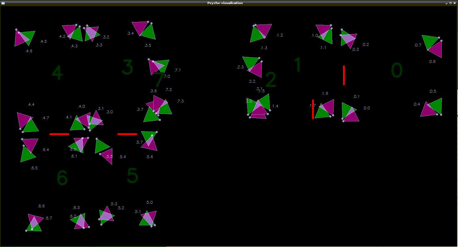
Testing the tracking
You can start running the visualization, which will show whether the camera orientations have been correctly identified and whether the frames are interpreted correctly. Ideally, the lines coming from the camera icons should intersect at one point.
Here's what happened:
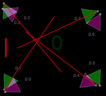
It looks like the truth, but the accuracy could clearly be higher. The first reason for imperfection that came to mind is distortion in camera lenses. This means that these distortions need to be compensated somehow.
Camera Calibration
The ideal camera has only one important parameter for me - the focal length. The real camera curve also needs to take into account the lens distortion and the offset of the matrix center.
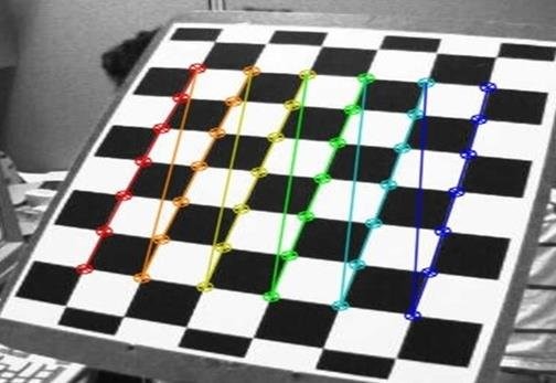
To measure these parameters, there is a standard calibration procedure, during which a set of photographs of a checkerboard are taken with a measured camera, in which the angles between the squares are recognized with subpixel precision.
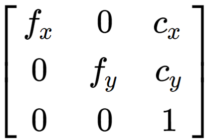
The result of the calibration is a matrix containing the focal lengths along two axes and the matrix offset relative to the optical center. All of this is measured in pixels.
As well as a vector of distortion coefficients

that allows you to compensate for lens distortions using pixel coordinates transformations.
By applying transformations with these coefficients to the coordinates of the marker on the frame, you can bring the system to a model of an ideal pinhole camera.
Running a new tracking test:
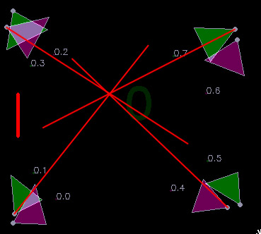
Much better! It looks so good that it even seems to work.
But the calibration process turns out to be very dreary: directly measure the coordinates of each camera, start displaying a picture from each camera, hang up stickers, measure the coordinates of each sticker, write the results into a table, and calibrate the lenses. All this took a couple of days and a kilogram of nerves. I decided to deal with tracking and write something more automated.
Calculating marker coordinates
And so, I got a bunch of straight lines, scattered in space, at the intersections of which there should be markers. Only straight lines in space do not actually intersect, but intersect, i.e. pass at some distance from each other. My task is to find the point as close as possible to both straight lines. Formally speaking, you need to find the midpoint of the segment that is perpendicular to both lines.
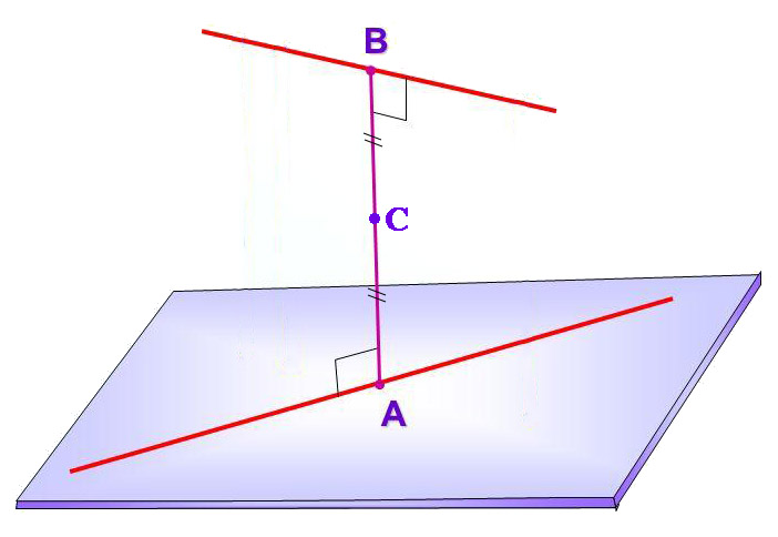
The length of the segment AB is also useful, because it reflects the "quality" of the result obtained. The shorter it is, the closer the straight lines are to each other, the better the result.
Then I wrote a tracking algorithm that calculates the intersections of lines in pairs (within the same color, from cameras that are at a sufficient distance from each other), looks for the best and uses it as marker coordinates. On the next frames, it tries to use the same pair of cameras to avoid a jump in coordinates when switching to tracking with other cameras.
In parallel, while developing a suit with sensors, I discovered a strange phenomenon. All sensors showed different values of the yaw angle (direction in the horizontal plane), as if each had its own north. First of all, it was useful to check whether I was mistaken in the data filtering algorithms or in the layout of the board, but I did not find anything. Then I decided to look at the raw data of the magnetometer and saw the problem.
The magnetic field in our room was directed VERTICALLY DOWN! Apparently, this is due to the iron in the building structure.
But VR glasses also use a magnetometer. Why don't they have this effect? I'm going to check. It turned out that he also has glasses ... If you sit still, you can see how the virtual world slowly but surely rotates around you in a random direction. In 10 minutes, he leaves almost 180 degrees. In our game, this will inevitably lead to out-of-sync between virtual and real realities and glasses broken against walls.
It seems that in addition to the coordinates of the glasses, you will have to determine their direction in the horizontal plane. The solution suggests itself - to put not one, but two identical markers on the glasses. It will allow you to determine the direction with an accuracy of 180 degrees, but taking into account the presence of built-in inertial sensors, this is quite enough.

The system as a whole worked, albeit with small jambs. But the decision was made to launch the quest, which was just about to be completed by our gamedev developer, who joined our mini-team. The entire playing area was destroyed, doors with sensors and magnetic locks were installed, and two interactive objects were made:
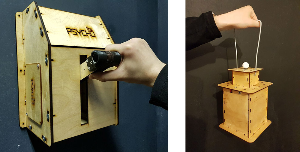
Players put on glasses, suits and computer backpacks and entered the play area. The tracking coordinates were sent to them via wi-fi and used to position the virtual character. Everything worked well enough, the visitors are happy. The most pleasant thing was to watch the horror and screams of especially impressionable visitors at the moments when virtual ghosts attacked them from the darkness =)
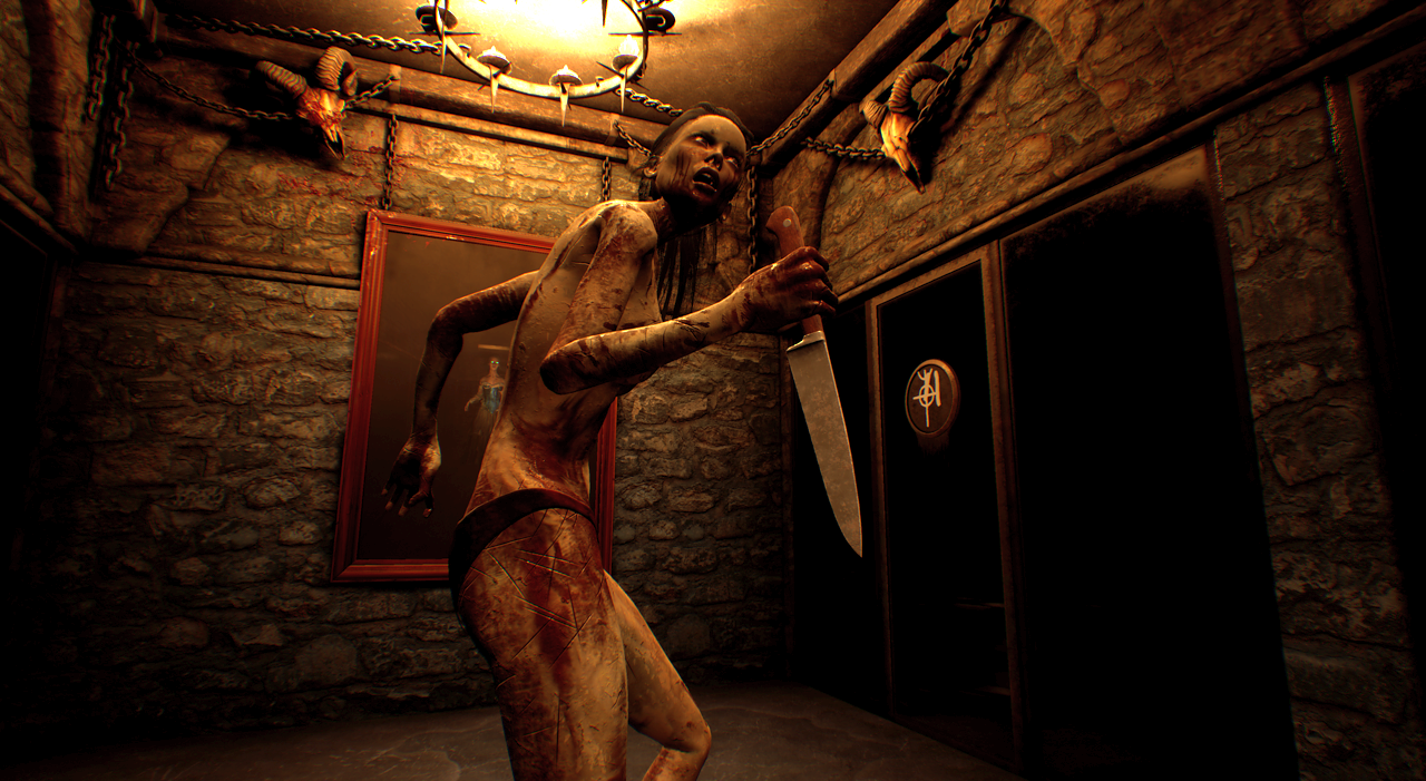
Scaling
Suddenly, we received an order for a large VR shooter for 8 players with guns in their hands. And these are 16 objects that need to be trembled. It was lucky that the scenario assumed the possibility of dividing the tracking into two zones of 4 players each, so I decided that there would be no problems, you could take the order and not worry about anything. It was impossible to test the system at home. required a large area and a lot of equipment that would be purchased by the customer, so before installation I decided to spend time automating the tracking calibration.
Autocalibration
It was incredibly inconvenient to direct the cameras, hang all these stickers, manually measure coordinates. I wanted to get rid of all these processes - hang up the cameras from the bulldozer, randomly walk with the marker in space and run the calibration algorithm. In theory, this should be possible, but how to approach writing an algorithm is not clear.
The first step was to centralize the entire system. Instead of dividing the play area into blocks of 8 cameras, I made a single server, which received the coordinates of points on the frames of all cameras at once.
The idea is as follows:
- I hang cameras and direct them to the play area by eye
- I start recording mode on the server, in which all 2D points coming from cameras are saved to a file
- I walk around a dark game location with a marker in my hands
- I stop recording and start the calibration data calculation, which calculates the locations, orientations and focal lengths of all cameras.
- as a result of the previous paragraph, a single space filled with cameras is obtained. Because this space is not tied to real coordinates, it has a random offset and rotation, which I subtract manually.
I had to shovel through a huge amount of material on linear algebra and write many hundreds of lines of Python code. So much so that I hardly remember how it works.
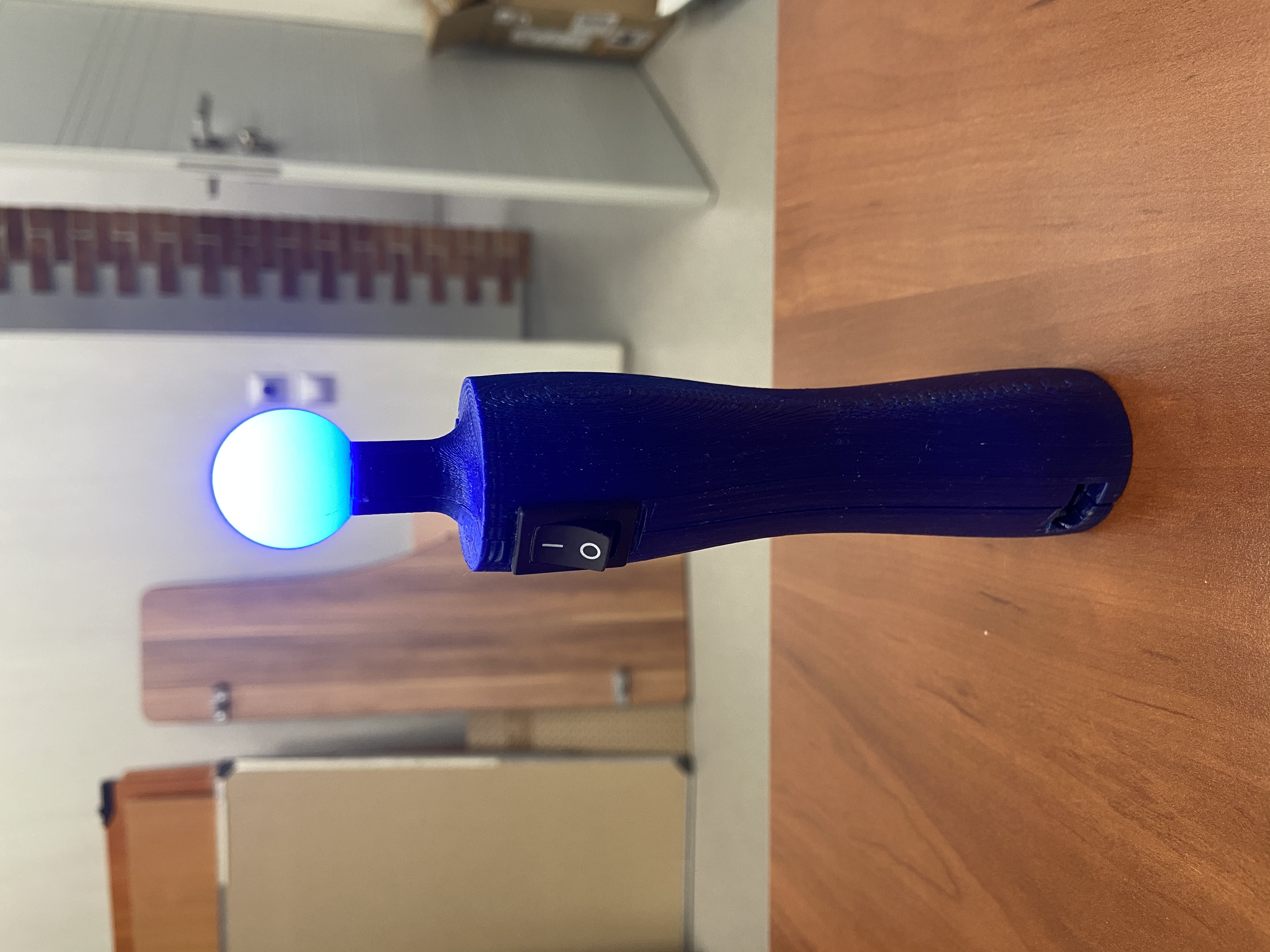
This is how a special calibration stick printed on a printer looks like.
Testing a large project
The problems started during testing at the facility a couple of weeks before the launch of the project. Identifying 8 different marker colors worked terribly, test players constantly teleported into each other, some colors did not differ at all from external highlights in the shopping complex. Vain attempts to fix something with each sleepless night drove me more and more into despair. All this was compounded by the lack of server performance when calculating tens of thousands of straight lines per second.
When the level of cortisol in the blood exceeded the theoretical maximum, I decided to look at the problem from a different angle. How can you reduce the number of colored dots without reducing the number of markers? Make tracking active. Let each player, for example, always have a red horn on the left horn. And the second one sometimes lights up green upon the arrival of a command from the server so that at one time it is lit only by one player. It turns out that the green light will seem to jump from one player to another, updating the tracking binding to the red light and resetting the magnetometer orientation error.
To do this, I had to run to the nearest chipidip, buy LEDs, wires, transistors, a soldering iron, electrical tape and hang the LED control functionality on the suit board on snot, which was not designed for this. It's good that when wiring the board, just in case, I hung a couple of free stm-ki legs on the contact pads.
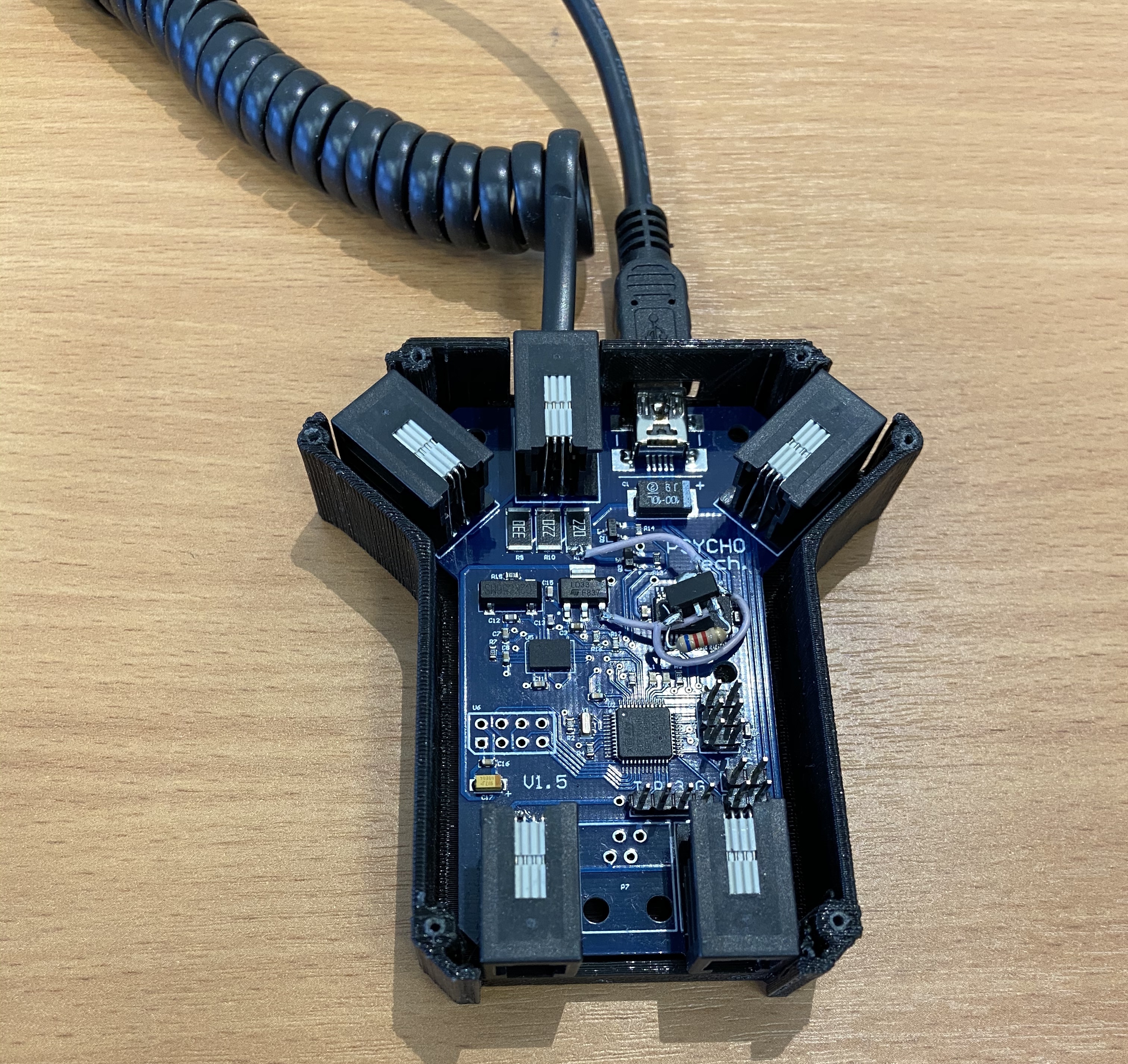
The tracking algorithms had to be considerably complicated, but in the end it worked! The teleportations of the players to each other disappeared, the load on the processor dropped, the highlights stopped interfering.
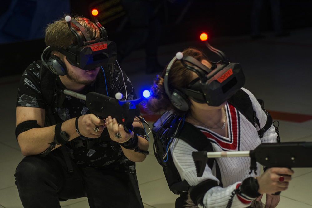
The project was successfully launched, first of all I made new suits boards with support for active tracking, and we made a hardware update.
How did it end?
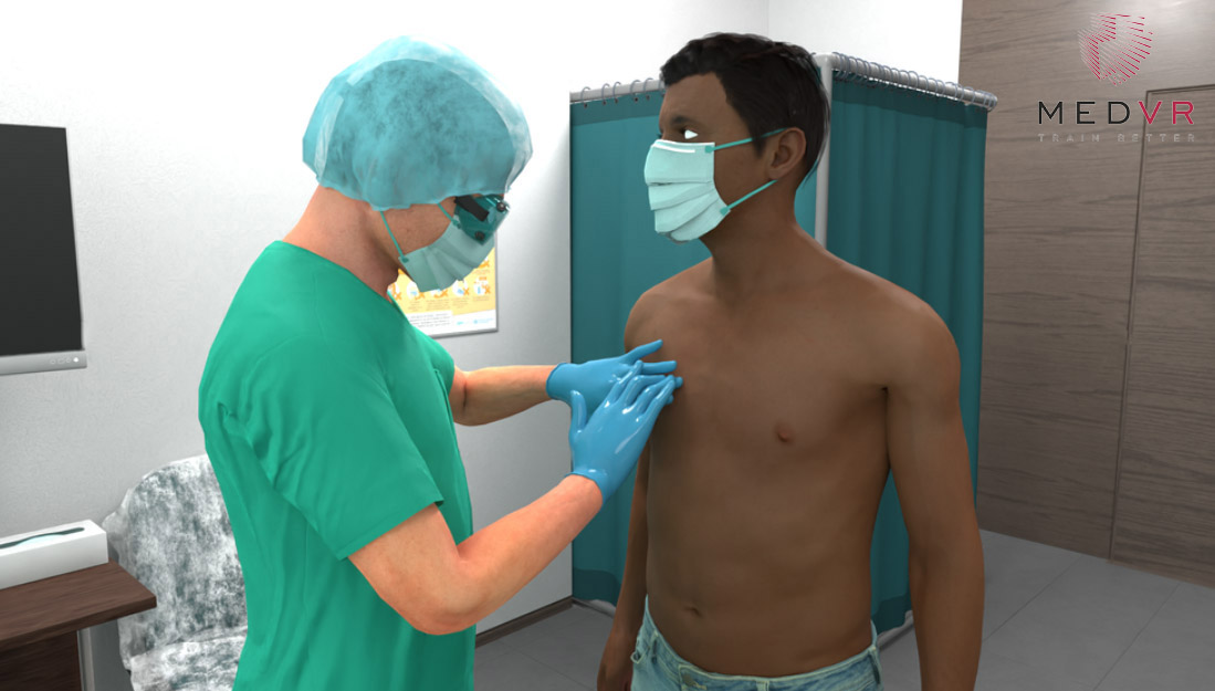
For 3 years we have opened many entertainment points around the world, but the coronavirus has made its own adjustments, which gave us the opportunity to change the direction of work in a more socially useful direction. We are now quite successful in developing medical simulators in VR. Our team is still small and we actively strive to expand our staff. If there are experienced UE4 developers looking for work among the readers of Habr, please write to me.
Traditional funny moment at the end of the article:
From time to time, during tests with a large number of players, a glitch arose in which the player was suddenly teleported for a short time to a height of several meters, which caused a corresponding reaction. It turned out that my camera model assumed the intersection of the matrix with an infinite line going from the marker. But she did not take into account that the camera has a front and a back, so the system looked for the intersection of endless lines, even if the point is behind the camera. Therefore, there were situations when two different cameras saw two different markers, but the system thought it was one marker at a height of several meters.
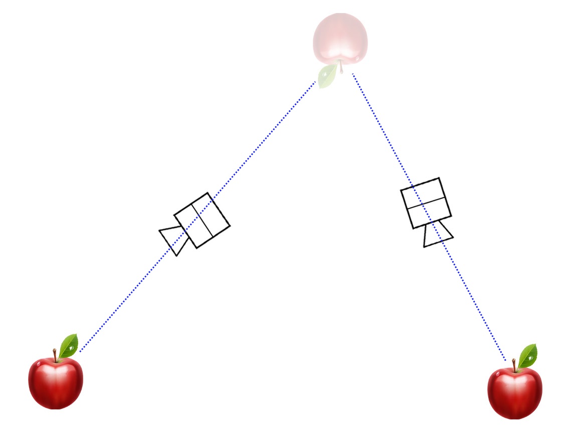
The system literally worked through the ass.