This article is not intended to be an exhaustive guide, but rather is a collection of sources of material and recommendations. In the article, I want to touch upon the issues that I had to face when choosing software tools for project development, as well as some cases of practical application of ESP32 modules. In the next article, I want to show an illustrative example of using the ESP32 as a control controller for a small two-wheeled mobile platform. Therefore, here we will consider such details as:
- Choosing a development environment;
- Setting up the working environment, compiling and loading the ESP-IDF project;
- GPIO input / output signal processing;
- Pulse width modulation using MCPWM module;
- PCNT hardware counter;
- WI-Fi and MQTT connection.
ESP32-WROOM-32E module overview
According to the datasheet the module contains:
MCU
- ESP32-D0WD-V3 embedded, Xtensa dual-core 32-bit LX6 microprocessor, up to 240 MHz
- 448 KB ROM for booting and core functions
- 520 KB SRAM for data and instructions
- 16 KB SRAM in RTC
Wi-Fi
- 802.11b / g / n
- Bit rate: 802.11n up to 150 Mbps
- A-MPDU and A-MSDU aggregation
- 0.4 µs guard interval support
- Center frequency range of operating channel: 2412 ~ 2484 MHz
Bluetooth
- Bluetooth V4.2 BR / EDR and Bluetooth LE specification
- Class-1, class-2 and class-3 transmitter
- AFH
- CVSD and SBC
Hardware
- Interfaces: SD card, UART, SPI, SDIO, I 2 C, LED PWM, Motor PWM, I 2 S, IR, pulse counter, GPIO, capacitive touch sensor, ADC, DAC
- 40 MHz crystal oscillator
- 4 MB SPI flash
- Operating voltage/Power supply: 3.0 ~ 3.6 V
- Operating temperature range: –40 ~ 85 °C
- Dimensions: See Table 1
Certification
- Bluetooth certification: BQB
- RF certification: FCC/CE-RED/SRRC
- Green certification: REACH/RoHS
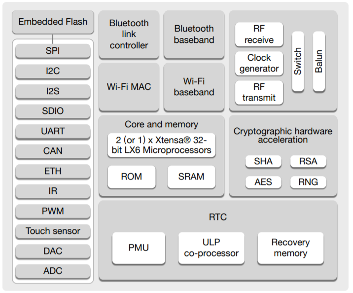
Functional block diagram
More details on the features of the microcontroller can be found on Wikipedia .
The module is based on the ESP32-D0WD-V3 * microcircuit. The embedded chip is designed with scalability and adaptability in mind. The central processing unit contains two cores that can be individually controlled, and the CPU clock speed is adjustable from 80 MHz to 240 MHz. The chip also has a low-power coprocessor that can be used in place of the CPU to save power when performing tasks that do not require a lot of computing power, such as monitoring the status of pins. ESP32 integrates a rich set of peripherals ranging from capacitive touch sensors, Hall sensors, SD card interface, Ethernet, high speed SPI, UART, I²S and I²C.
Technical documentation is presented on the official resource .
Information about the pinout of the ESP-WROOM-32 module can be easily found on the open spaces of the network, as here
Choosing a development environment
Arduino IDE
Microcontrollers of the AVR family, and then the Arduino platform, appeared long before the ESP32. One of the key features of the Arduino is its relatively low barrier to entry, allowing almost anyone to create something quickly and easily. The platform has made an important contribution to the open source hardware community and has allowed a huge number of radio amateurs to join. The Arduino IDE is free to download from offsite . Despite the obvious limitations compared to a professional development environment, the Arduino IDE covers 90% of what is required for hobby projects. There is also a sufficient number of articles on the network on the topic of installing and configuring the Arduino IDE for programming ESP32 modules, for example: Arduino core for the ESP32 , habr.com, voltiq.ru and randomnerdtutorials.com .
When programming the ESP32 in the Arduino environment, you need to take into account the pinout as indicated on the arduino-esp32 page .
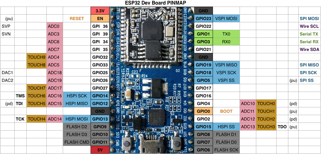
ESP32 module pinout
The main advantage of this development approach is quick entry and ease of creation of projects using the same principles as for Arduino. And also the use of many libraries, as for Arduino. Another nice feature is the ability to combine Arduino libraries and design principles with the original ESP-IDF framework.
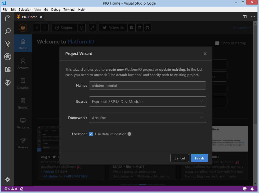
PlatformIO
As stated on the official resource : “Cross-platform PlatformIO IDE and Unified Debugger · Static Code Analyzer and Remote Unit Testing. Multi-platform and Multi-architecture Build System · Firmware File Explorer and Memory Inspection »In other words, PlatformIO is an ecosystem for embedded device development supporting multiple platforms including Arduino and ESP32. The IDE is Visual Studio Code or Atom. Installation and configuration is quite simple - after installing the code editor, select PlatformIO from the list of plugins and install. Again, there are a lot of materials on this topic on the net, starting from the official source here and here , and continuing with articles with detailed illustrations here and here....
Compared to the Arduino IDE, PlatformIO has all the qualities of a modern development environment: project organization, plug-in support, code completion, and much more.
A feature of development on PlatformIO is a unified project structure for all platforms
project_dir
├── lib
│   └── README
├── platformio.ini
└── src
    └── main.cpp
Each PlatformIO project contains a configuration file named platformio.ini in the root of the project. platformio.ini has sections (each denoted by a [title]) and key / value pairs within sections. Lines starting with a dot-semicolon ";" are ignored and can be used for comments. Multiple value parameters can be specified in two ways:
- separating the value with "," (comma + space);
- multi-line format, where each new line begins with at least two spaces.
The next development feature for ESP32 is the ability to choose a framework: Arduino or ESP-IDF. By choosing Arduino as a framework, we get the previously described development benefits.
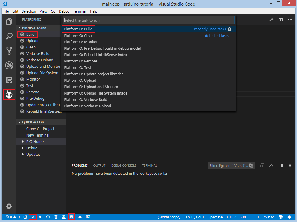
PlatformIO includes convenient tools for building, downloading and debugging projects
Espressif IoT Development framework
For ESP32, Espressif has developed a framework called the IoT Development Framework known as “ESP-IDF”. It can be found on Github . The project contains very good documentation and is supplied with examples that you can take as a base. Setting up and setting up the environment is well documented in the Get Started section . There are several options for installing and working with the framework.
Cloning a project from the repository and manually installing the utilities.
Cloning a project from Github
mkdir -p ~/esp
cd ~/esp
git clone --recursive https://github.com/espressif/esp-idf.git
For Windows, installation of development utilities is possible using the installer or using scripts for the command line:
cd %userprofile%\esp\esp-idf
install.bat
For PowerShell
cd ~/esp/esp-idf
./install.ps1
For Linux and macOS
cd ~/esp/esp-idf
./install.sh
The next step is to set up environment variables . If the development tools were installed on Windows using the installer, then a shortcut to the command console is added to the menu and to the desktop, after which you can open the command shell and work with projects. Alternatively, to run a Windows command shell:
%userprofile%\esp\esp-idf\export.bator Windows PowerShell:
.$HOME/esp/esp-idf/export.ps1Linux and macOS:
. $HOME/esp/esp-idf/export.shYou should pay attention to the space between the period and the path to the script.
Further in the guide it is recommended to add an alias to the script for setting environment variables in the user profile if you work on Linux or macOS. To do this, copy and paste the following command into your shell profile (.profile, .bashrc, .zprofile, etc.):
alias get_idf='. $HOME/esp/esp-idf/export.sh'By calling the get_idf command in the console, the required environment variables are exported. In my case, it was also necessary to register an alias for starting the python virtual environment
alias esp_va=’source $HOME/.espressif/python_env/idf4.2_py2.7_env/bin/activate’and add it to the next alias
alias get_idf='esp_ve && . $HOME/esp/esp-idf/export.sh'To create a new project from scratch, you can clone the sources from github.com or copy from the directory with examples esp-idf / examples / get-started / hello_world /.
Information about the project structure, compilation, loading, configuration utilities, etc. is located here .
The project is a directory with the following structure:
- myProject/
             - CMakeLists.txt
             - sdkconfig
             - components/ - component1/ - CMakeLists.txt
                                         - Kconfig
                                         - src1.c
                           - component2/ - CMakeLists.txt
                                         - Kconfig
                                         - src1.c
                                         - include/ - component2.h
             - main/       - CMakeLists.txt
                           - src1.c
                           - src2.c

             - build/
The project configuration is contained in the sdkconfig file in the root directory. To change the settings, you need to call the idf.py menuconfig command (or possibly idf.py.exe menuconfig on Windows).
Usually two applications are created in one project - "project app" (the main executable file, ie your custom firmware) and "bootloader app" (program of the bootloader of the project).
"Components" are modular pieces of stand-alone code that are compiled into static libraries (.a files) and linked to the application. Some of these are provided by ESP-IDF itself, others may be obtained from other sources.
The idf.py command line utility provides an interface to easily manage project builds. Its location on Windows is% userprofile% \. Espressif \ tools \ idf-exe \ 1.0.1 \ idf.py.exe. She controls the following instruments:
- CMake - configures the project to build
- Console project builder: Ninja, or GNU Make)
- esptool.py - for flashing modules.
Each project has one top-level CMakeLists.txt file that contains build settings for the entire project. The minimal file configuration includes the following required lines:
cmake_minimum_required(VERSION 3.5)
include($ENV{IDF_PATH}/tools/cmake/project.cmake)
project(myProject)
An ESP-IDF project can be thought of as a collection of components in which the main directory is the main component that runs the code. Therefore, this directory also contains the CMakeLists.txt file. Most often, its structure is similar:
idf_component_register(SRCS "main.c" INCLUDE_DIRS ".")Where it is indicated that the source file main.c must be registered for the component, and the header files are contained in the current directory. If necessary, you can rename the main directory by setting EXTRA_COMPONENT_DIRS in the CMakeLists.txt project. More details can be found here .
In addition, the directory contains the original main.c (the name can be any) file with an entry point - the void app_main (void) function.
Custom components will be created in the components directory. The process is described in more detail in the Component Requirements section .
Connecting the ESP32 module to a computer in most cases is done using a USB cable like Arduino boards due to the existing bootloader. The process is described in more detail here... The only thing that is needed is the presence of a USB to UART converter driver in the system, which can be downloaded from the given source. After installing the driver, you need to determine the COM port number in the system to load the compiled firmware into the module.
Configuring the project.
The default settings are fine in most cases. But to call the console menu interface, you need to go to the project directory and type in the command line:
idf.py menuconfig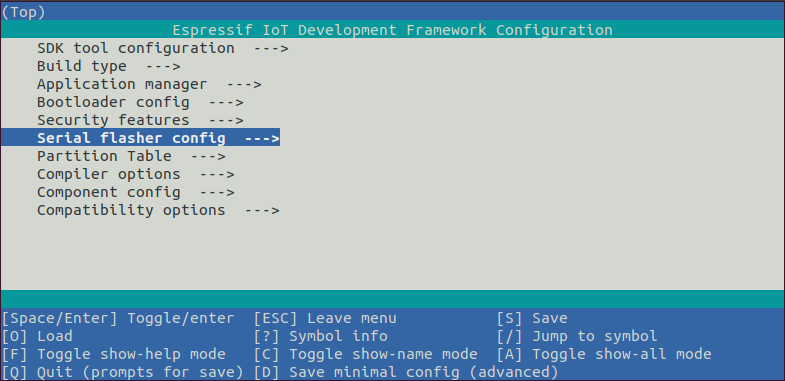
Menu with configuration settings
After calling this command, the sdkconfig file will be created if it was not previously or if it was reconfigured. In earlier tutorials, you will see make menuconfig commands that are obsolete.
Adding custom settings to the sdkconfig file is possible manually, for example:
#
# WiFi Settings
#
CONFIG_ESP_HOST_NAME=" "
CONFIG_ESP_WIFI_SSID="  "
CONFIG_ESP_WIFI_PASSWORD=""
But the preferred method is using an additional configuration file Kconfig.projbuild, which must be located in the directory with the component. The content of the file can be as follows:
# put here your custom config value
menu "Example Configuration"
config ESP_WIFI_SSID
    string "Keenetic"
    default "myssid"
    help
    SSID (network name) for the example to connect to.

config ESP_WIFI_PASSWORD
    string "password"
    default "mypassword"
    help
    WiFi password (WPA or WPA2) for the example to use.
endmenu
After calling the idf.py menuconfig command, an additional section is automatically added in the sdkconfig file. Calling the idf.py menuconfig command is also possible in the PlatformIO project, however, you need to take into account the fact that the structure of the PlatformIO project is different from the classic ESP-IDF, because of which the sdkconfig file can be re-generated and tweak custom settings. The above options are possible here - editing the file by hand, temporarily renaming the src directory in main, or setting up the CMakeLists.txt file.
Compiling and loading the project.
To build a project, you need to type the command
idf.py buildThis command will compile the application and all ESP-IDF components, and then generate the loader, partition table, and application binaries.
$ idf.py build
Running cmake in directory /path/to/hello_world/build
Executing "cmake -G Ninja --warn-uninitialized /path/to/hello_world"...
Warn about uninitialized values.
-- Found Git: /usr/bin/git (found version "2.17.0")
-- Building empty aws_iot component due to configuration
-- Component names: ...
-- Component paths: ...

... (more lines of build system output)

[527/527] Generating hello-world.bin
esptool.py v2.3.1

Project build complete. To flash, run this command:
../../../components/esptool_py/esptool/esptool.py -p (PORT) -b 921600 write_flash --flash_mode dio --flash_size detect --flash_freq 40m 0x10000 build/hello-world.bin  build 0x1000 build/bootloader/bootloader.bin 0x8000 build/partition_table/partition-table.bin
or run 'idf.py -p PORT flash'
It should be borne in mind that the initial compilation process of even a simple project takes time, so, unlike the Arduino framework, many additional ESP-IDF modules are compiled. Further changes to the sources only lead to compilation of the same files. An exception is configuration change.
To download the compiled binaries (bootloader.bin, partition-table.bin and hello-world.bin) to the ESP32 board, run the command:
idf.py -p PORT [-b BAUD] flashwhere we replace PORT with what we need (COM1, / dev / ttyUSB1), and we can optionally change the download speed by specifying the required values for BAUD
To track the loaded program, you can use any com port monitoring utility, such as HTerm , CoolTerm , or use the IDF Monitor monitoring utility , to start it, enter the command:
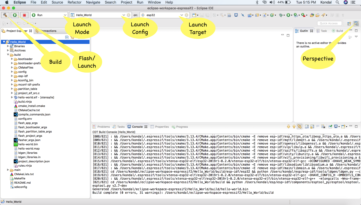
idf.py -p PORT monitorESP-IDF Eclipse Plugin
The documentation for installing and configuring the plugin is located here
Presets for use:
- Java 11 and above; (although it works on java 8, possibly because of this glitches);
- Python 3.5 and above;
- Eclipse 2020-06 CDT;
- Git;
- ESP-IDF 4.0 and above;
The plugin is quite well integrated into the development environment, automates the lion's share of the functionality. But, unfortunately, not without a fly in the ointment. In Eclipse versions later than 2019-09, there is still a bug with indexing source files in ESP-IDF projects on Windows.In

addition, there are other glitches when the project simply does not build for unknown reasons. Only closing the project and restarting Eclipse helps.
ESP-IDF Visual Studio Code Extension
And the last, in my opinion the most interesting option is the official plugin for Visual Studio Code.
Like PlatformIO, it can be easily installed from the extensions section. Installing and configuring the ESP-IDF framework in this extension is presented as an onboarding menu, which is also described in the description. Downloading and installing all components occurs automatically in the process of going through the menu stages. All screenshots of the process can be cited, but they are intuitive and require little or no explanation. In favor of PlatformIO, a more convenient toolkit for building, downloading and monitoring a project can be noted. In contrast, the ESP-IDF plug-in is controlled using a command menu that can be invoked using the F1 key, or a combination of keys described in the manual.
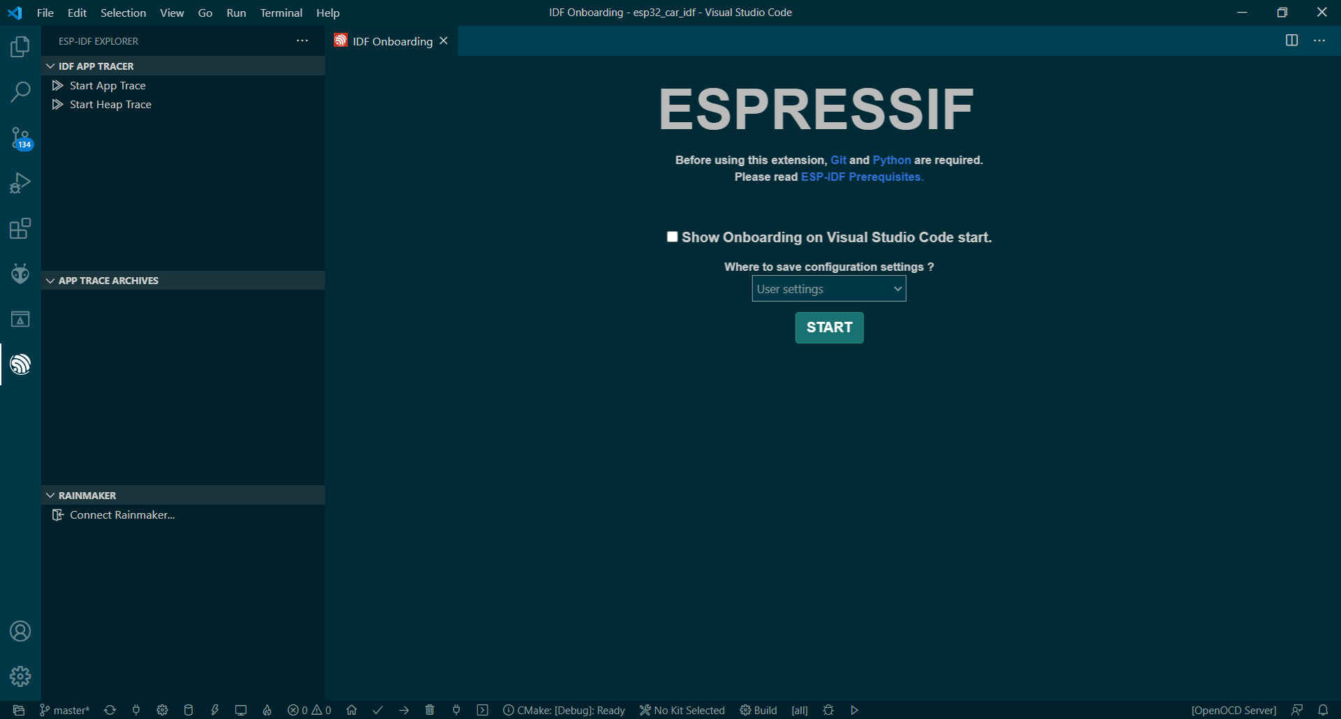
Initial plugin setup
The advantage of using the plugin is that the classic project structure is respected, there is no need to somehow tinker with the settings (in PlatformIO, such a need arises). There is one nuance, if we want to open a previously created project in Visual studio code with the ESP-IDF plugin, then we just need to copy the .vscode directory to the root of the project, which can be obtained by generating at least once a template project using ESP- IDF plugin.

Command menu
FreeRTOS
According to wikipedia, FreeRTOS is a real-time multitasking operating system (RTOS) for embedded systems. FreeRTOS provides multitasking by sharing CPU time by all threads, or in OS terminology, tasks. In my opinion, the most complete and intelligible FreeRTOS manual in Russian is here . In the original language, the manuals can be studied from the official source . I will only give a picture of the status of tasks.
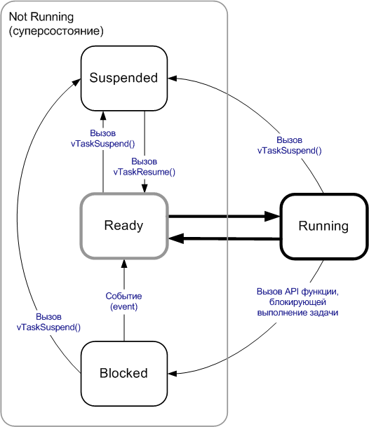
FreeRTOS has been ported to a wide variety of hardware platforms including the Xtensa processors used in the ESP32. More details can be found in the documentation.
GPIOs
GPIO or universal input / output is the ability to discretely control a pin with a "1" or "0" signal.
As the name implies, such pins have two operating modes - input or output. In the first case, we read the value, in the second, we write it down. Another important factor when dealing with GPIOs is the voltage level. The ESP32 is a 3.3V device. Therefore, you should be careful when working with other devices that have a voltage of 5V or higher. It is also important to understand that the maximum current that can be applied to the GPIO pin is 12 mA. To use the GPIO functions provided by ESP-IDF, we need to connect the driver / gpio.h header. You can then call gpio_pad_select_gpio () to specify the function of this pin. There are 34 different GPIOs available on the ESP32. They are designated as:
- GPIO_NUM_0 - GPIO_NUM_19
- GPIO_NUM_21 - GPIO_NUM_23
- GPIO_NUM_25 - GPIO_NUM_27
- GPIO_NUM_32 - GPIO_NUM_39
The following numbering is not included in the number of pins 20, 24, 28, 29, 30 and 31. The
pinout table can be found here .
Please note that pins GPIO_NUM_34 - GPIO_NUM_39 - use only input mode. They cannot be used for signal output. In addition, pins 6, 7, 8, 9, 10 and 11 are used to interact with an external flash card via SPI, it is not recommended to use them for other purposes, but if you really want to, you can. The gpio_num_t data type is an enumeration with values corresponding to pin numbers. It is recommended to use these values rather than numbers. The direction of the pin is set using the gpio_set_direction () function. For example, to set a pin as an output:
gpio_set_direction(GPIO_NUM_17, GPIO_MODE_OUTPUT);To set a pin as an input:
gpio_set_direction(GPIO_NUM_17, GPIO_MODE_INPUT);If we have configured GPIO as an output, then we can set its value to 1 or 0 by calling gpio_set_level ().
The following example switches GPIOs once per second:
gpio_pad_select_gpio(GPIO_NUM_17);
gpio_set_direction(GPIO_NUM_17, GPIO_MODE_OUTPUT);
while(1) {
    printf("Off\n");
    gpio_set_level(GPIO_NUM_17, 0);
    vTaskDelay(1000 / portTICK_RATE_MS);
    printf("On\n");
    gpio_set_level(GPIO_NUM_17, 1);
    vTaskDelay(1000 / portTICK_RATE_MS);
}
As an alternative to setting all the attributes of individual pins, we can set the properties of one or more contacts by calling the gpio_config () function. It takes a gpio_config_t structure as input and sets the direction, pull up, pull down, and interrupt settings for all pins represented in the bitmask.
For instance:
gpio_config_t gpioConfig;
gpioConfig.pin_bit_mask = (1 << 16) | (1 << 17);
gpioConfig.mode = GPIO_MODE_OUTPUT;
gpioConfig.pull_up_en = GPIO_PULLUP_DISABLE;
gpioConfig.pull_down_en = GPIO_PULLDOWN_ENABLE;
gpioConfig.intr_type = GPIO_INTR_DISABLE;
gpio_config(&gpioConfig);
Pull up and pull down settings
It is usually read that the GPIO input pin is high or low. This means that it is connected to a power source or to ground. However, if the pin is not connected to anything, then it is in a "floating" state. It is often necessary to set the initial level of an unconnected pin to high or low. In this case, a hardware (connection using resistors) or software pull-up of the output is made, respectively, to + V - pull up or to 0 - pull down. In the ESP32 SDK, we can define a GPIO as a pull up or pull down using the gpio_set_pull_mode () function. This function takes as input the number of the pin we want to set and the pull-up mode associated with that pin.
For instance:
gpio_set_pull_mode (21, GPIO_PULLUP_ONLY);GPIO interrupt handling
To detect a change in the input signal on a pin, we can periodically poll its status, but this is not the best solution for a number of reasons. First, we have to cycle through the check, wasting CPU time. Secondly, at the moment of polling, the state of the pin may no longer be relevant due to the delay and you can skip the input signals. The solution to these problems is interruption. An interruption is like a doorbell. Without ringing, we'll have to check periodically to see if anyone is at the door. In the source code, we can define an interrupt callback function that will be called when the pin changes the value of its signal. We can also determine what is causing the handler to be called by setting the following parameters:
- Disable - do not cause interruption when the signal changes;
- PosEdge - call the interrupt handler when changing from low to high;
- NegEdge - call an interrupt handler when changing from high to low;
- AnyEdge - invoke the interrupt handler either when changing from low to high, or when changing from high to low;

An interrupt handler can be marked to load into RAM at compile time. By default, the generated code is in flash memory. If you mark it as IRAM_ATTR beforehand, it will be ready for immediate execution from RAM.
void IRAM_ATTR my_gpio_isr_handle(void *arg) {...}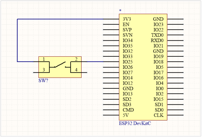
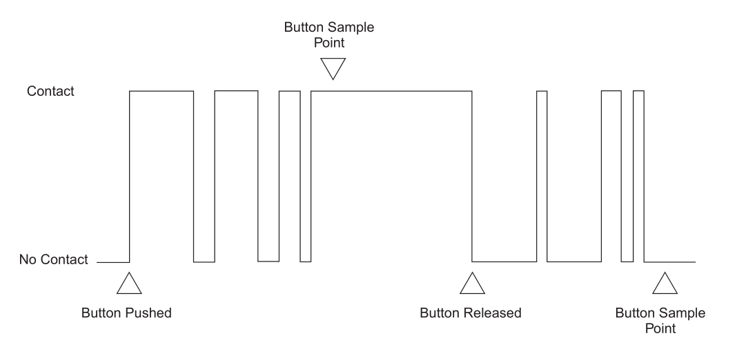
Those who have worked with microcontrollers know that processing of input signals from buttons is accompanied by contact bounce. Which can be interpreted as a series of transitions, and therefore a series of interrupt handler events. To do this, we must add contact bounce handling to the code. To do this, we need to read the original event, wait until the vibrations subside, and then re-sample the input state.
The following example demonstrates interrupt handling of input signals. I highly recommend that you familiarize yourself with queue management in FreeRTOS for further understanding of the code, if you are not already familiar with it. The example shows two tasks:
- test1_task, which is unlocked when an interrupt event occurs when the signal is activated on pin 25 and the message "Registered a click" is displayed to the console once;
- test2_task is periodically polled, and when the signal on pin 26 is activated, the message “GPIO 26 is high!” is output to the console every 100 ms.
The example also has a software timer xTimer set, it is optional for this case, rather as an example of asynchronous delay.
Anti-bounce is performed using the timeval_durationBeforeNow function , which checks if the press lasts more than 100ms. There are other anti-bounce software patterns, but the meaning is about the same. ESP-IDF also includes an example of how GPIO works.
Input signal processing
#include <stdio.h>
#include "freertos/FreeRTOS.h"
#include "freertos/task.h"
#include "driver/gpio.h"
#include "esp_log.h"
#include "freertos/queue.h"
#include "c_timeutils.h"
#include "freertos/timers.h"

static char tag[] = "test_intr";
static QueueHandle_t q1;
TimerHandle_t xTimer;
#define TEST_GPIO (25)

static void handler(void *args) {
    gpio_num_t gpio;
    gpio = TEST_GPIO;
    xQueueSendToBackFromISR(q1, &gpio, NULL);
}

void test1_task(void *ignore) {
    struct timeval lastPress;
    ESP_LOGD(tag, ">> test1_task");
    gpio_num_t gpio;
    q1 = xQueueCreate(10, sizeof(gpio_num_t));
    gpio_config_t gpioConfig;
    gpioConfig.pin_bit_mask = GPIO_SEL_25;
    gpioConfig.mode = GPIO_MODE_INPUT;
    gpioConfig.pull_up_en = GPIO_PULLUP_DISABLE;
    gpioConfig.pull_down_en = GPIO_PULLDOWN_ENABLE;
    gpioConfig.intr_type = GPIO_INTR_POSEDGE;
    gpio_config(&gpioConfig);
    gpio_install_isr_service(0);
    gpio_isr_handler_add(TEST_GPIO, handler, NULL);
    while(1) {
        //ESP_LOGD(tag, "Waiting on queue");
        BaseType_t rc = xQueueReceive(q1, &gpio, portMAX_DELAY);
        //ESP_LOGD(tag, "Woke from queue wait: %d", rc);
        struct timeval now;
        gettimeofday(&now, NULL);
        if (timeval_durationBeforeNow(&lastPress) > 100) {
            if(gpio_get_level(GPIO_NUM_25)) {
                ESP_LOGD(tag, "Registered a click");
                if( xTimerStart( xTimer, 0 ) != pdPASS ) {
                    // The timer could not be set into the Active state.
                }
            }
        }
        lastPress = now;
    }
    vTaskDelete(NULL);
}

void test2_task(void *ignore) {
    gpio_set_direction(GPIO_NUM_26, GPIO_MODE_INPUT);
    gpio_set_pull_mode(GPIO_NUM_26, GPIO_PULLDOWN_ONLY);
    while(true) {
        if(gpio_get_level(GPIO_NUM_26)) {
            ESP_LOGD(tag, "GPIO 26 is high!");
            if( xTimerStart( xTimer, 0 ) != pdPASS ) {
                    // The timer could not be set into the Active state.
                }
        }
        vTaskDelay(100/portTICK_PERIOD_MS);
    }
}

void vTimerCallback( TimerHandle_t pxTimer ) {
    ESP_LOGD(tag, "The timer has expired!");
}

void app_main(void)
{
    xTaskCreate(test1_task, "test_task1", 5000, NULL, 8, NULL);
    xTaskCreate(test2_task, "test_task2", 5000, NULL, 8, NULL);

    xTimer = xTimerCreate("Timer",       // Just a text name, not used by the kernel.
                            2000/portTICK_PERIOD_MS,   // The timer period in ticks.
                            pdFALSE,        // The timers will auto-reload themselves when they expire.
                            ( void * ) 1,  // Assign each timer a unique id equal to its array index.
                            vTimerCallback // Each timer calls the same callback when it expires.
                        );
}
PCNT (Pulse Counter)
The PCNT (Pulse Counter) module is designed to count the number of rising and / or falling edges of the input signal. Each block of the module has a 16-bit signed register and two channels that can be configured to increase or decrease the counter value. Each channel has an input signal that captures the change in the signal, as well as a control input that can be used to enable or disable counting. The inputs have additional filters that can be used to eliminate unwanted signal spikes.
The PCNT counter has eight independent units, numbered from 0 to 7. In the API, they are specified using pcnt_unit_t. Each module has two independent channels, numbered 0 and 1, indicated by pcnt_channel_t.
The configuration is provided separately for each device channel using pcnt_config_t and covers:
- Unit number and channel number to which this configuration belongs;
- GPIO numbers of pulse input and gate input;
- Two pairs of parameters, pcnt_ctrl_mode_t and pcnt_count_mode_t, to define how the counter reacts depending on the state of the control signal and how the rising / falling edges are counted.
- Two limit values (min / max) that are used to set watchpoints and trigger interrupts when the pulse counter reaches a certain limit.
The configuration of a specific channel is then done by calling the pcnt_unit_config () function with the above pcnt_config_t configuration structure as an input parameter.
To disable a pulse or control input in the configuration, you need to specify PCNT_PIN_NOT_USED instead of the GPIO number.
After configuring with pcnt_unit_config (), the counter starts running immediately. The accumulated counter value can be checked by calling pcnt_get_counter_value ().
The following functions allow you to control the counter operation: pcnt_counter_pause (), pcnt_counter_resume () and pcnt_counter_clear ()
It is also possible to dynamically change previously set counter modes using pcnt_unit_config () by calling pcnt_set_mode ().
If desired, the pulse input pin and the control input pin can be changed on the fly using pcnt_set_pin ().
The PCNT module has filters on each of the pulse and control inputs, adding the ability to ignore short spikes in signals. The length of the ignored pulses is provided in APB_CLK clock cycles by calling pcnt_set_filter_value (). The current filter settings can be checked with pcnt_get_filter_value (). The APB_CLK cycle operates at 80 MHz.
The filter is started / paused by calling pcnt_filter_enable () / pcnt_filter_disable ().
The following events, defined in pcnt_evt_type_t, can trigger an interrupt. The event occurs when the pulse counter reaches certain values:
- : counter_l_lim counter_h_lim, pcnt_config_t;
- 0 1, pcnt_set_event_value ().
- = 0
To register, enable or disable the interrupt for the above events, you must call pcnt_isr_register (), pcnt_intr_enable (), and pcnt_intr_disable (). To enable or disable events when thresholds are reached, you will also need to call pcnt_event_enable () and pcnt_event_disable ().
To check which thresholds are currently set, use the pcnt_get_event_value () function.
An example from ESP-IDF is presented here .
I used a PCNT counter to calculate the wheel speed. To do this, it is necessary to count the number of pulses per revolution, and then reset the counter.
Sample code
typedef struct {
      uint16_t delay; //delay im ms
      int pin;
      int ctrl_pin;
      pcnt_channel_t channel;
      pcnt_unit_t unit;
      int16_t count;
} speed_sensor_params_t;


esp_err_t init_speed_sensor(speed_sensor_params_t* params) {
      /* Prepare configuration for the PCNT unit */
    pcnt_config_t pcnt_config;
    // Set PCNT input signal and control GPIOs
    pcnt_config.pulse_gpio_num = params->pin;
    pcnt_config.ctrl_gpio_num = params->ctrl_pin;
    pcnt_config.channel = params->channel;
    pcnt_config.unit = params->unit;
    // What to do on the positive / negative edge of pulse input?
    pcnt_config.pos_mode = PCNT_COUNT_INC;   // Count up on the positive edge
    pcnt_config.neg_mode = PCNT_COUNT_DIS;   // Keep the counter value on the negative edge
    pcnt_config.lctrl_mode = PCNT_MODE_REVERSE; // Reverse counting direction if low
    pcnt_config.hctrl_mode = PCNT_MODE_KEEP;    // Keep the primary counter mode if high
    pcnt_config.counter_h_lim = INT16_MAX;
    pcnt_config.counter_l_lim = - INT16_MAX;

     /* Initialize PCNT unit */
    esp_err_t err = pcnt_unit_config(&pcnt_config);

    /* Configure and enable the input filter */
    pcnt_set_filter_value(params->unit, 100);
    pcnt_filter_enable(params->unit);

    /* Initialize PCNT's counter */
    pcnt_counter_pause(params->unit);
    pcnt_counter_clear(params->unit);

    /* Everything is set up, now go to counting */
    pcnt_counter_resume(params->unit);
    return err;
}

int32_t calculateRpm(speed_sensor_params_t* params) {
    pcnt_get_counter_value(params->unit, &(params->count));
    int32_t rpm = 60*(1000/params->delay)*params->count/PULSE_PER_TURN;
    pcnt_counter_clear(params->unit);
    return rpm;
}
Pulse width modulation (PWM) using MCPWM module
Information about the module is presented here
There are many articles on the net on the topic of PWM , especially if you search in relation to Arduino.
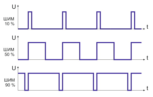
Wikipedia gives a short and succinct definition - Pulse-width modulation (PWM) - the process of controlling power by pulsing the device on and off. The principle of regulation using PWM is to change the pulse width at a constant amplitude and frequency of the signal.
The PWM frequency of Arduino is 488.28 Hz., The resolution is 8 bits (0 ... 255), and it is possible to use six hardware pins 3, 5, 6, 9, 10, 11. However, using the register settings of the AVR microcontroller, you can achieve other values PWM frequency.
The ESP32 microcontroller has in its arsenal a separate MCPWM module, or rather two modules, each of which has three pairs of PWM pins.
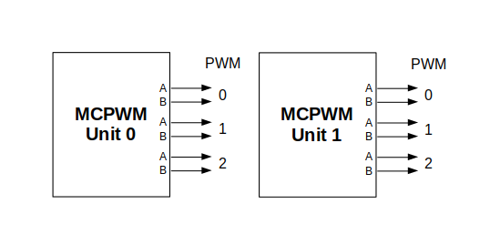
Further, in the documentation, the outputs of a separate block are marked as PWMxA / PWMxB.
A more detailed block diagram of the MCPWM block is presented below. Each A / B pair can be synchronized with any of three timers: Timer 0, 1, and 2. The same timer can be used to synchronize more than one pair of PWM outputs. Each unit can also collect input data such as sync signals, detect alarms such as overcurrent or motor overvoltage, and receive feedback from capture signals such as rotor position.
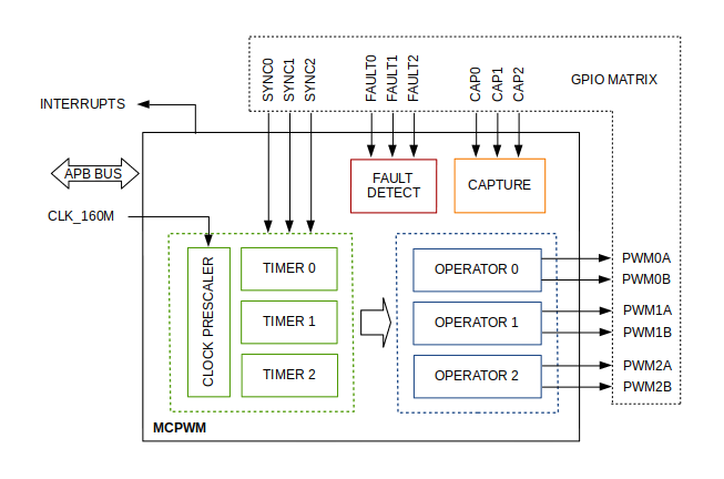
The scope of the configuration depends on the type of motor, in particular how many outputs and inputs are required and what the sequence of signals will be for controlling the motor.
In our case, we will describe a simple configuration for driving a brushed DC motor that uses only a few of the available MCPWM resources. An example circuit is shown below. It includes an H-bridge for switching the polarization of the voltage supplied to the motor (M) and providing sufficient current to drive it.

The configuration includes the following steps:
- Selection of the MPWn block that will be used to drive the motor. There are two modules available on the ESP32 board from those listed in mcpwm_unit_t.
- Initializes two GPIOs as outputs on the selected module by calling mcpwm_gpio_init (). The two output signals are usually used to drive the motor to the right or left. All available signal parameters are listed in mcpwm_io_signals_t. To set more than one pin at a time, use the mcpwm_set_pin () function along with mcpwm_pin_config_t.
- Timer selection. There are three timers available on the device. Timers are listed in mcpwm_timer_t.
- Setting the timer frequency and bootstrap in the mcpwm_config_t structure.
- Calling mcpwm_init () with the above parameters.
The PWM control methods are as follows:
- mcpwm_set_signal_high () mcpwm_set_signal_low (). . A B .
- — , mcpwm_start () mcpwm_stop (). .
- , mcpwm_set_duty () . mcpwm_set_duty_in_us (), . mcpwm_get_duty (). , mcpwm_set_duty_type (). A B mcpwm_generator_t. . mcpwm_init (), , mcpwm_duty_type_t.
An example of a code for a brushed motor is here.
In my project, I practically used the code from the example, slightly correcting it and adding a second motor control. For independent control of PWM channels, each of them must be configured with a separate timer, for example MCPWM_TIMER_0 and CPWM_TIMER_1:
Sample code
void mcpwm_example_gpio_initialize(void)
{
    mcpwm_gpio_init(MCPWM_UNIT_0, MCPWM0A, GPIO_PWM0A_OUT);
    mcpwm_gpio_init(MCPWM_UNIT_0, MCPWM0B, GPIO_PWM0B_OUT);
    mcpwm_gpio_init(MCPWM_UNIT_0, MCPWM1A, GPIO_PWM1A_OUT);
    mcpwm_gpio_init(MCPWM_UNIT_0, MCPWM1B, GPIO_PWM1B_OUT);
    //mcpwm_gpio_init(MCPWM_UNIT_0, MCPWM_SYNC_0, GPIO_SYNC0_IN);

    mcpwm_config_t pwm_config;
    pwm_config.frequency = 1000;    //frequency = 500Hz,
    pwm_config.cmpr_a = 0;    //duty cycle of PWMxA = 0
    pwm_config.cmpr_b = 0;    //duty cycle of PWMxb = 0
    pwm_config.counter_mode = MCPWM_UP_COUNTER;
    pwm_config.duty_mode = MCPWM_DUTY_MODE_0;
    mcpwm_init(MCPWM_UNIT_0, MCPWM_TIMER_0, &pwm_config);    //Configure PWM0A & PWM0B with above settings
    mcpwm_init(MCPWM_UNIT_0, MCPWM_TIMER_1, &pwm_config);    //Configure PWM0A & PWM0B with above settings
          // deadtime (see clock source changes in mcpwm.c file)
    mcpwm_deadtime_enable(MCPWM_UNIT_0, MCPWM_TIMER_0, MCPWM_BYPASS_FED, 80, 80);   // 1us deadtime
    mcpwm_deadtime_enable(MCPWM_UNIT_0, MCPWM_TIMER_1, MCPWM_BYPASS_FED, 80, 80);
}
Connecting to WI-Fi and working with MQTT
The topic of the Wi-FI protocol is quite extensive. A series of separate articles will be needed to describe the protocol. In the official guide, see the Wi-Fi driver section . A description of the software API is here . Code examples can be viewed here
Wi-Fi Libraries provide support for configuring and monitoring ESP32 Wi-Fi networking functions. The following configurations are available:
- ( STA Wi-Fi). ESP32 .
- AP ( Soft-AP ). ESP32.
- AP-STA (ESP32 , ).
- (WPA, WPA2, WEP . .)
- ( ).
- Wi-Fi IEEE802.11.
MQTT
You can get acquainted with the topic here or here . The ESP-IDF manual with examples is here .
To set up MQTT in code, you first need to connect to a Wi-Fi network. Then establish a connection to the broker. The message is processed in a callback, the parameter of which is esp_mqtt_event_handle_t event. If the event type is MQTT_EVENT_DATA, then the topic and data can be parsed. You can customize different behavior as a result of successful connection, disconnection and topic subscriptions.
Wi-Fi connection example:
tcpip_adapter_init();
    wifi_event_group = xEventGroupCreate();
    ESP_ERROR_CHECK(esp_event_loop_create_default());
    ESP_ERROR_CHECK(esp_event_handler_register(WIFI_EVENT, ESP_EVENT_ANY_ID, &wifi_event_handler, NULL));
    ESP_ERROR_CHECK(esp_event_handler_register(IP_EVENT, IP_EVENT_STA_GOT_IP, &ip_event_handler, NULL));
    wifi_init_config_t cfg = WIFI_INIT_CONFIG_DEFAULT();
    ESP_ERROR_CHECK( esp_wifi_init(&cfg) );
    ESP_ERROR_CHECK( esp_wifi_set_storage(WIFI_STORAGE_RAM) );
    ESP_ERROR_CHECK( esp_wifi_set_mode(WIFI_MODE_STA) );
    wifi_config_t sta_config = {
        .sta = {
            .ssid = CONFIG_ESP_WIFI_SSID,
            .password = CONFIG_ESP_WIFI_PASSWORD,
            .bssid_set = false
        }
    };
    ESP_ERROR_CHECK( esp_wifi_set_config(WIFI_IF_STA, &sta_config) );
    ESP_LOGI(TAG, "start the WIFI SSID:[%s] password:[%s]", CONFIG_ESP_WIFI_SSID, "******");
    ESP_ERROR_CHECK( esp_wifi_start() );
    ESP_LOGI(TAG, "Waiting for wifi");
    xEventGroupWaitBits(wifi_event_group, BIT0, false, true, portMAX_DELAY);

    //MQTT init
    mqtt_event_group = xEventGroupCreate();
    mqtt_app_start(mqtt_event_group);
Connecting to MQTT broker
void mqtt_app_start(EventGroupHandle_t event_group)
{
    mqtt_event_group = event_group;
    const esp_mqtt_client_config_t mqtt_cfg = {
        .uri = "mqtt://mqtt.eclipse.org:1883",    //mqtt://mqtt.eclipse.org:1883
        .event_handle =  mqtt_event_handler,
        .keepalive = 10,
        .lwt_topic = "esp32/status/activ",
        .lwt_msg = "0",
        .lwt_retain = 1,
    };

    ESP_LOGI(TAG, "[APP] Free memory: %d bytes", esp_get_free_heap_size());
    client = esp_mqtt_client_init(&mqtt_cfg);
    esp_mqtt_client_start(client);
MQTT handler
esp_err_t mqtt_event_handler(esp_mqtt_event_handle_t event)
{
    esp_mqtt_client_handle_t client = event->client;
    int msg_id;
    command_t command;
    // your_context_t *context = event.context;
    switch (event->event_id) {
        case MQTT_EVENT_CONNECTED:
             xEventGroupSetBits(mqtt_event_group, BIT1);
            ESP_LOGI(TAG, "MQTT_EVENT_CONNECTED");
            msg_id = esp_mqtt_client_subscribe(client, "esp32/car/#", 0);
            msg_id = esp_mqtt_client_subscribe(client, "esp32/camera/#", 0);
            ESP_LOGI(TAG, "sent subscribe successful, msg_id=%d", msg_id);
            break;

        case MQTT_EVENT_DISCONNECTED:
            ESP_LOGI(TAG, "MQTT_EVENT_DISCONNECTED");
            break;

        case MQTT_EVENT_SUBSCRIBED:
            ESP_LOGI(TAG, "MQTT_EVENT_SUBSCRIBED, msg_id=%d", event->msg_id);
            msg_id = esp_mqtt_client_publish(client, "esp32/status/activ", "1", 0, 0, 1);
            ESP_LOGI(TAG, "sent publish successful, msg_id=%d", msg_id);
            break;

        case MQTT_EVENT_UNSUBSCRIBED:
            ESP_LOGI(TAG, "MQTT_EVENT_UNSUBSCRIBED, msg_id=%d", event->msg_id);
            break;

        case MQTT_EVENT_PUBLISHED:
            ESP_LOGI(TAG, "MQTT_EVENT_PUBLISHED, msg_id=%d", event->msg_id);
            break;

        case MQTT_EVENT_DATA:
            ESP_LOGI(TAG, "MQTT_EVENT_DATA");
            printf("TOPIC=%.*s\r\n", event->topic_len, event->topic);
            printf("DATA=%.*s\r\n", event->data_len, event->data);
            memset(topic, 0, strlen(topic));
            memset(data, 0, strlen(data));
            strncpy(topic, event->topic, event->topic_len);
            strncpy(data, event->data, event->data_len);
            command_t command = {
                .topic = topic,
                .message = data,
            };
            parseCommand(&command);
            break;

        case MQTT_EVENT_ERROR:
            ESP_LOGI(TAG, "MQTT_EVENT_ERROR");
            break;

        default:
            break;
    }
    return ESP_OK;
}
This concludes my story about using the ESP32 module. The article considered examples on ESP-IDF, as a framework that makes the most of the module's resources. Programming using other platforms such as javaScript, MicroPython, Lua can be found on the related resources. In the next article, as already mentioned, I will give a practical example of using a microcontroller, and also compare the software approach of Arduino and ESP-IDF.