Above, we considered two basic concepts in electrical engineering - an ideal voltage generator and an ideal current generator.
An ideal voltage generator produces a given voltage U (pressure in the water-pipe analogy) at any load (resistance of an external circuit).
Moreover, in accordance with Ohm's law, I = U / R, even if R tends to zero, and the current increases to infinity.
The internal resistance of an ideal voltage generator is 0.
An ideal current generator produces a given current I (flow in the water-pipe analogy), even if the resistance of the external circuit tends to infinity. In this case, the voltage across the load also tends to infinity U = I * R.
The internal resistance of an ideal current generator is ∞.
Here you can see a certain symmetry, dualism.
We considered a capacitor C which can accumulate a charge (therefore it is called capacitance) C = Q / U. The larger the capacitance, the slower the voltage (pressure) increases when the charge U = Q / C is pumped into the capacitor.
If the charge capacity is very large (tends to infinity), then such a capacitor of infinite capacity will be an ideal voltage generator . It will never be discharged and at the same time it can produce a current of any magnitude, and the voltage across it will remain constant.
The symmetrical (dual) element to the capacitor will be inductance . Inductance is designated by the letter L (see diagram below).
, — L.

, . , .
, I .
wiki - “ .”
( ). « ». .
, ( ), — ( ).
« !»
« !»
S4 , ! , .
( ) , .
, , , , , .
( ) wiki - https://ru.wikipedia.org/wiki/
“ , . , , . . , ( ), — ( ). .”
, , , , , — .
— , , , « » 0 . . .
. .
.
. 13 - .
.
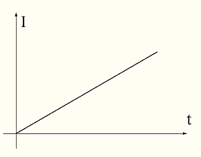
.
.
.
, ?

« — ».
(hint - . ? ?)
,
, , . ? , , . , () () .
— () . . , . . )
, , . 16

U. S2 . , - ( S2).
0, . , 0. ( ). , () - . 0. . « !» , . , - . , . U !
, .
.. , , . , . , .
. - () .
. .
.
UPD.
, .
.13?
- . .

.
U=const ( U – ), .
? , — ( ) ( ).
.
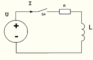
.17 R . ( , R, )
. S4 . , , 0! . U . - Ur=I*R. I*R, I 0, 0, U. . 0 ( 19 « » « 0 45 »). . , . . I*R U , 0 ( ).
.
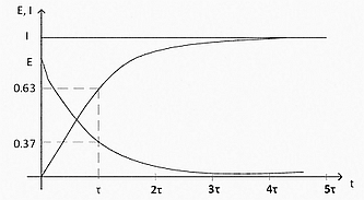

. . .
« . , . . . , 0 , , , .»
.. , , . , — .. , I=U/R.
, . , . ( ), , , . 1:
VL = – L*(di/dt), (1)
:
VL – ( ), ;
L – ;
di/dt – .
, . , « » , " ." , , 0. , .
« » « » . , , — , . , , . . , , . , . , . — . (), . , .
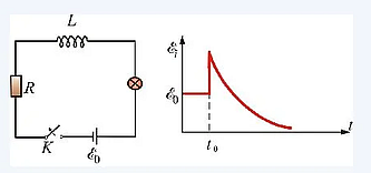
The picture is wrong. In the correct version, when the source was disconnected, a resistor was connected and the circuit remained closed.
Consider the following chain
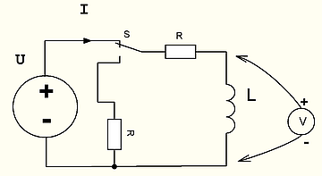
Backfill question: What will be the voltage across the inductance at the first moment after switching the key S from the upper position to the lower one?
Hint: You don't have to put your brain out trying to figure out what sign the EMF of self-induction will have and what will happen to it next. It is necessary to apply a simple rule: The current in the inductor at the first moment of time after switching remains unchanged. Further apply Ohm's law.