In short, I will try to teach the reader how to use the latest Mixed SIM module of the Altium Designer software package using the example of reasoning and analysis of a useful technology ...
PART ONE: PWM as a result of the evolution of Linear Systems.
Great ideas and ingenious solutions
In the world of technology, there are various methods of achieving certain goals, both final and intermediate. Some techniques are so successful that they are widely used in their niche and with high efficiency. Electronics is no exception, where great ideas and ingenious solutions have been found and applied, perhaps more than in other engineering fields. The clearest example is the use of Pulse Width Modulation (PWM) signals (energy), which is used in any modern electronic device, be it an autopilot, smartphone, tablet, laptop, LED spotlight or even an electronic toy and helps to effectively / economically solve the following tasks:
Conversion of voltage or current for power supply of individual circuits, nodes and blocks of an electronic device (stabilization of supply voltage for circuits, stabilization of current for power supply of lighting devices based on LEDs)
Highly economical and efficient amplification of audio signal power (UMZCH class D with efficiency close to 100%)
Control of actuators such as hydraulic or pneumatic valves (drives of aerodynamic planes of wings, rudders of aircraft and missiles, automatic transmissions of cars, ICE and turbine control units, industrial automation in the broadest sense)
Converting a digital code to a specific proportional voltage or current value (is an alternative to many DACs)
( ) (, )
, “ ” .
, , .
, 5 2. 10 36. ? , “” 5. , Altium Designer - Mixed Simulation* :
*: Mixed Simulation Guide_SS, , , , Simulation Generic Components Altium Designer.
“Linear regulator” :

, . V2 Ref R1 , Q1 (). V(Load)=5 V(Ref).
R1: , , : 5/2, .. 2,5 , 2.5 .
(Operating Point) : , ,.
: 10-36, , .. V(Load)(V(V1)), : DC Sweep, :
DC Sweep V1, , 10-36 0,1:

Output Expression / (+Add) , :

V(Load)(V(V1))
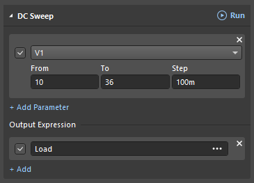
: RUN DC Sweep :
 On the ordinate - the voltage in the load V (Load) equal to 5 Volts")
- .
. , V1, R1, DC Sweep (+Add) Output Expression V(V1) , P(R1) (V(V1)) P(V1)(V(V1)) 2 :


(RUN) DC Sweep :

10 2 , .. 50%, 36 , , ?, , ! DC Sweep (+Add) Output Expression , :
( P(R1) / P(V1) ) V(V1) * 100, 3 :

(RUN) DC Sweep :

. , 50% 14%. , . , .
, , , , , ?
, , ..:
Rq1 = (Vsource - Load) / IcQ1 (.. Q1 , )
DC Sweep. (+Add) Output Expression :
 ^ - 1, as a result, the function will look like this: (Vsorce-Load) * ic (Q1) ^ - 1:")
, :

(RUN) DC Sweep :

Rq1 Q1. : , Rq1 , .. , . , , . Q1 R2 , ( R1):
, :

DC Sweep ( ) :

DC Sweep R2, , 0-100 0,1 (+Add) Output Expression : P(R2) P(R1) R2:

(RUN) DC Sweep “” , Messages :

, , , , , . , , - , “ ”, , ( !) , ( - ), “ ” .
R2… , 0 , , 1 , , :

(RUN) DC Sweep :

… !, . , , , , : Chart Options :

Logarithmic, OK. :

, “ 10 ” ( ), “ 10 ”, .. , 0,1-1 1-10 10-100 !
, , , DC Sweep R2 100 .. 10 :

Chart Options , , ! .
. , - R1, - R2. , (.. ) 0 , !. , . , , .
It's time to look inside the PWM, so to speak, to understand its anatomy, which we will consider in the second part of our story: "A thread with a needle in the tissue of energy."