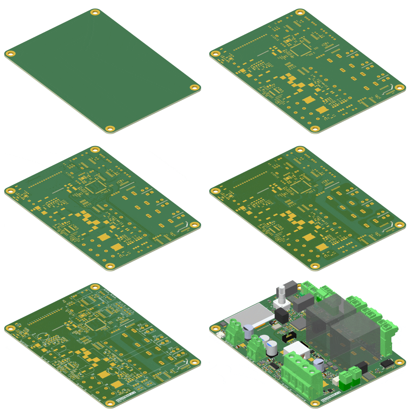
The previous article described the circuitry of the backup power controller. Such a controller can be useful in a variety of technical systems and devices. Therefore, the design of the board was chosen as neutral as possible with the ability to move the controls to a separate panel.
Choosing a board design and routing it is a cascade of tradeoffs. Compromises arise when you need to satisfy a whole list of desires including, but not limited to:
, .
- .
. .
4- , .
. , SMD .
, .
Altium Designer. .
standalone Altium 10 . , 3 . PDN Analyzer .
Altium .
:


, , . .
.
. , .

Altium . .
:


- . , . . , , .
: (clearance) (creepage).

(creepage) , . . creepage.

. , . , .
. , , , , - . .
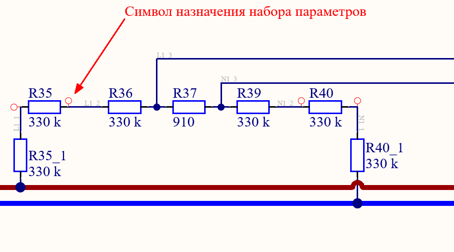
.
. Altium .
.

, ( , ) .
. . ( SMD )

. . .
SDM , . , ( ). .
, 0.3 . . . .
. . .


. , .
- .

, Altium PDF .
. , , .
. , . .


-. , . , , , .
, , « », , . -.
, -. , .
. . . - , .
- -- . , , .
Altium PDN Analyzer . . . .
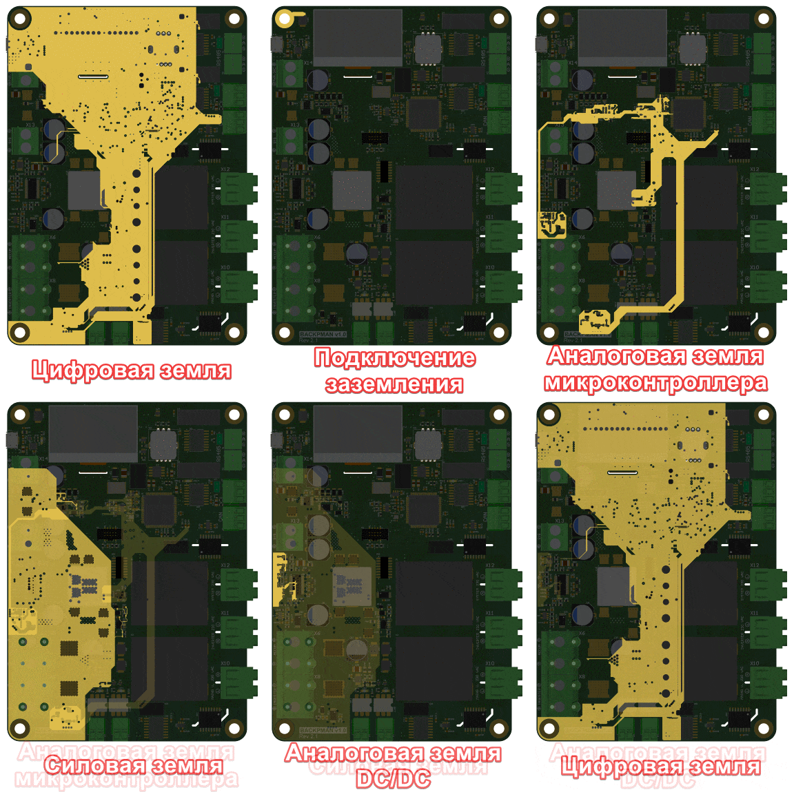
:
DC/DC
DC/DC
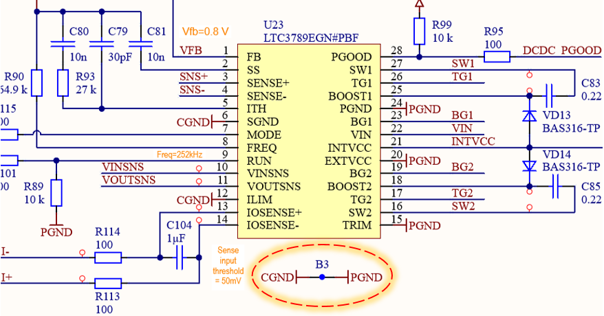
- ,

After this division on the board, these lands were already routed as separate, unconnected nets. And of course, we did not forget about the rule of minimizing the loop of return currents, i.e. the signals from each domain went over or near the land polygon of that domain.
The resulting topology of each land is shown below.

This concludes the description of the trace. As far as possible in the format of a short article, I tried to highlight the most important points in my opinion.
The next step will be programming, commissioning and testing the board. But more on that later.