In the manual, we will tell you how to assemble a rather curious device with great potential, which allows you to apply various inscriptions on the asphalt while driving. Everything in the world is illusory and temporary ... And this project illustrates this well.
Introduction
I started this project because I wanted to leave my mark on the world, but I didn't want to leave any consequences.
I also wanted a complex project for my new 3D printer that included programming for the Arduino.
Finally, I like to create things using as much of the good available as possible.
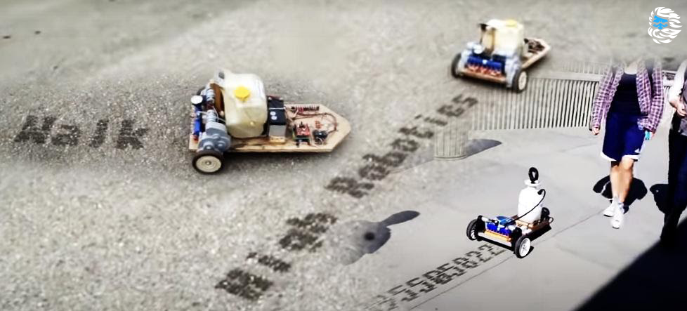
As you can see in my videos, StreetWriter fits all of this. He writes messages 8 inches ( 20.32 cm ) high with water on the sidewalk while driving and leaves no residue when the water evaporates.
I built two StreetWriters with slight design differences between them. This tutorial is based on the second build, which has been slightly improved.
The StreetWriter supplies pressurized water to a manifold that contains 8 automotive fuel injectors. As the StreetWriter moves, the Arduino controls the fuel injectors, spraying water onto the sidewalk. The message being written is one of 8 that was written to the SD card connected to the Arduino. The operator can easily select among the messages and can record new messages to the SD card using a computer. There are no restrictions on the length of the message, except for the amount of water in the tank. The longest post I have written so far is pi, with an accuracy of 300 characters.
Parts, materials and tools
Drive wheels assembly (used from an old Power Wheels car);
- "Found" 5-inch (12.7 cm) discs;
- "Found" rotary eccentric wheel;
- «» ( );
- ;
- «» ;
- () 1/8 NPT;
- 1/8 «NPT;
- ;
- 12 ( - 6-7 , , LiPo);
- Uno;
- Arduino Shield (EKT-1016 Tindie.com);
- SD-card shield Arduino (www.sparkfun.com/products/12761);
- ;
- , 3D- ( );
- 8 ( Ebay);
- ;
- Dclips;
- ;
- 3 ;
- ;
- - ;
- Screwdriver
Step 1: General device
The goal of this project was to write text messages using water as a temporary means of writing. After a short time, the water will evaporate and the message will disappear without a trace.
I was less interested in the attractiveness of the end device than in its functionality. However, if you are interested not only in functionality but also in appearance, there is a lot of room for improvement.
Overall, the unit is a motorized platform that uses 8 nozzles to spray water in a controlled manner as the platform moves.
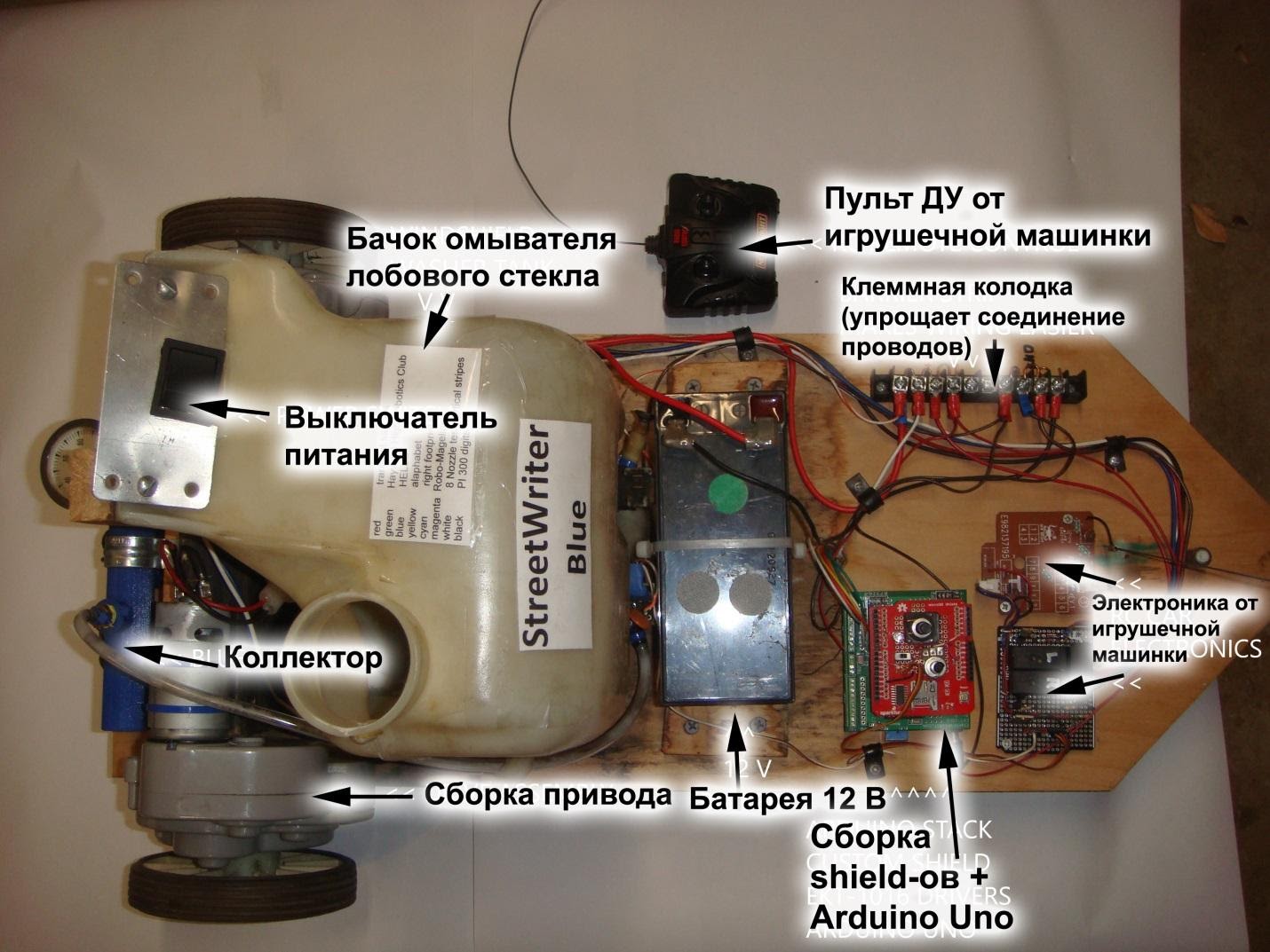
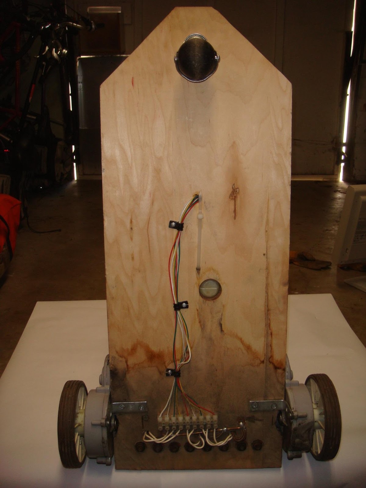
As shown in the pictures for this step, the platform is a wooden plank powered by two motors taken from small toy wheeled cars.
The windshield washer reservoir with a pumping system creates the required water pressure for the operation of 8 fuel injectors under the control of the Arduino Uno.
The Arduino has a shield that provides the current needed to operate the fuel injectors, which the Arduino cannot directly supply. There is also a special shield for Arduino with an SD card reader, as well as a number of components to select the file to be used and set the amount of water pressure for writing messages.
Also, a StreetWriter remote control is installed - using converted electronics from a radio-controlled car.
Read on for more details.
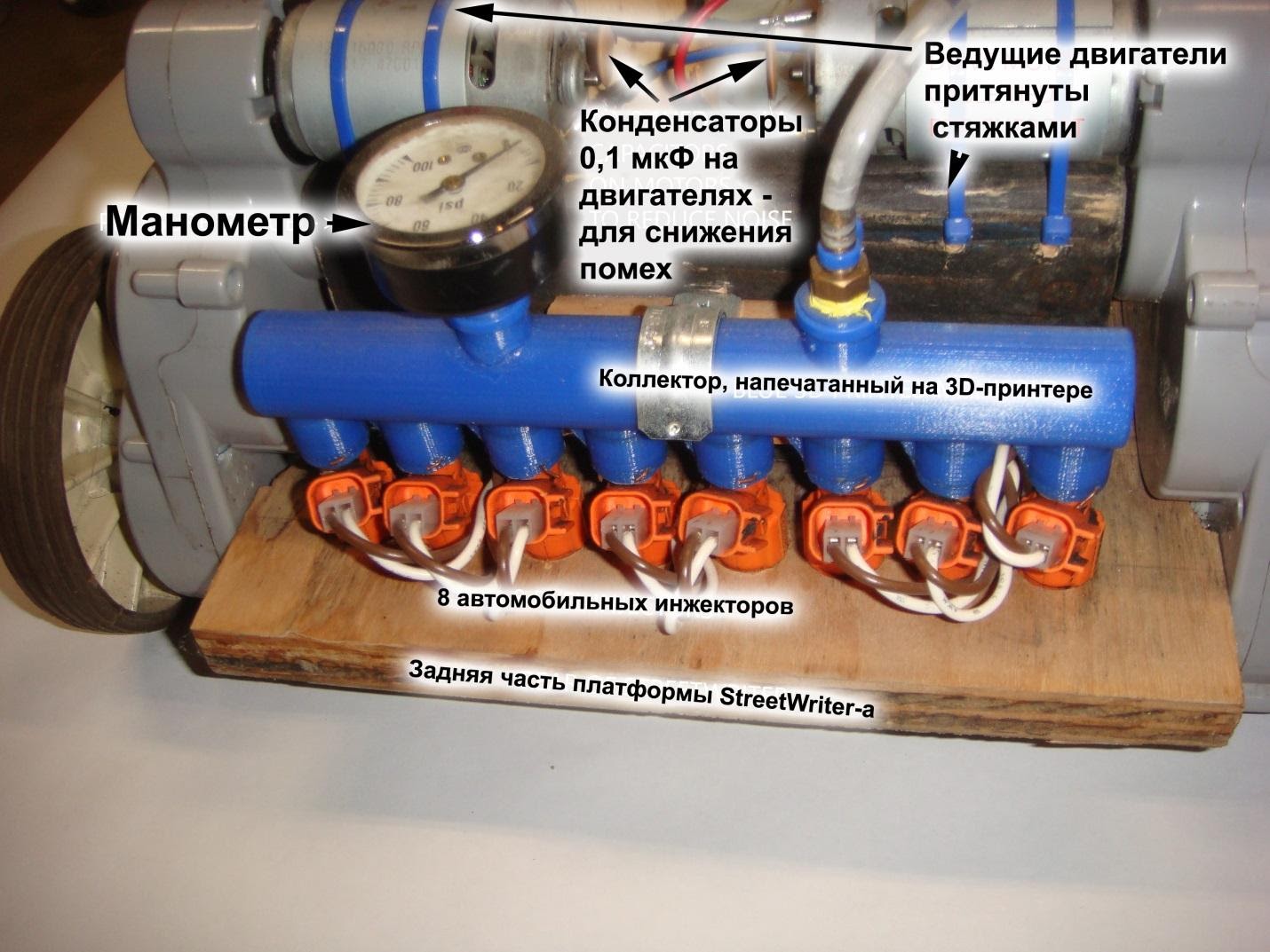
Step 2: fuel injectors and manifold
In many ways, this step forms the basis of StreetWriter's design.
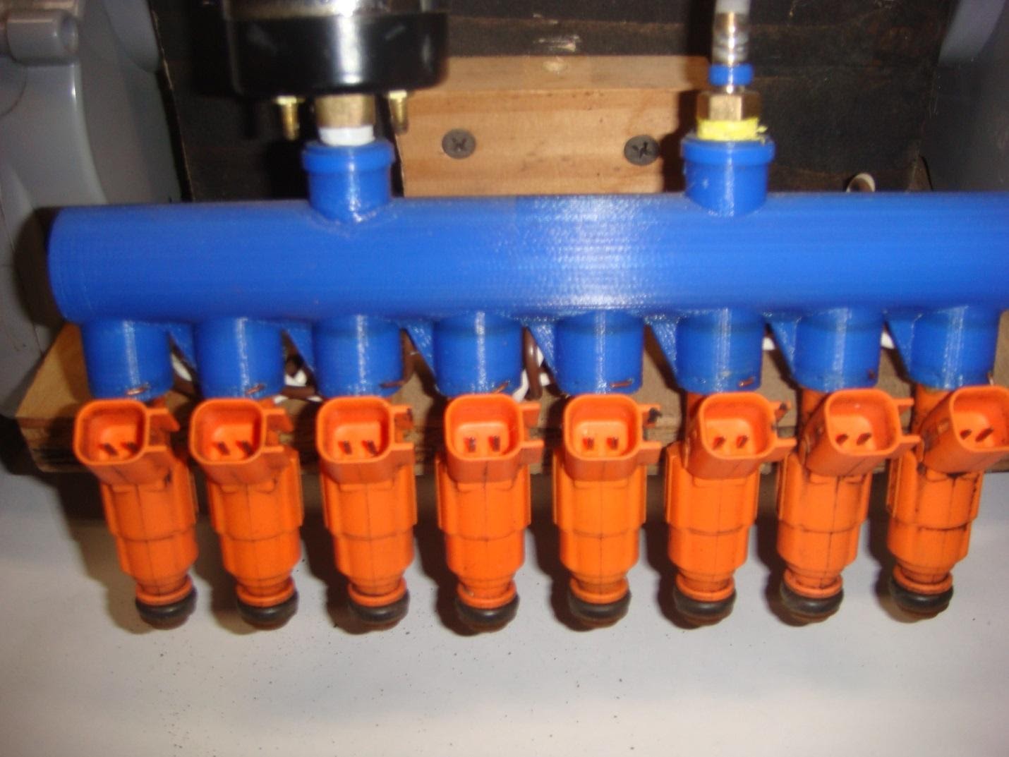
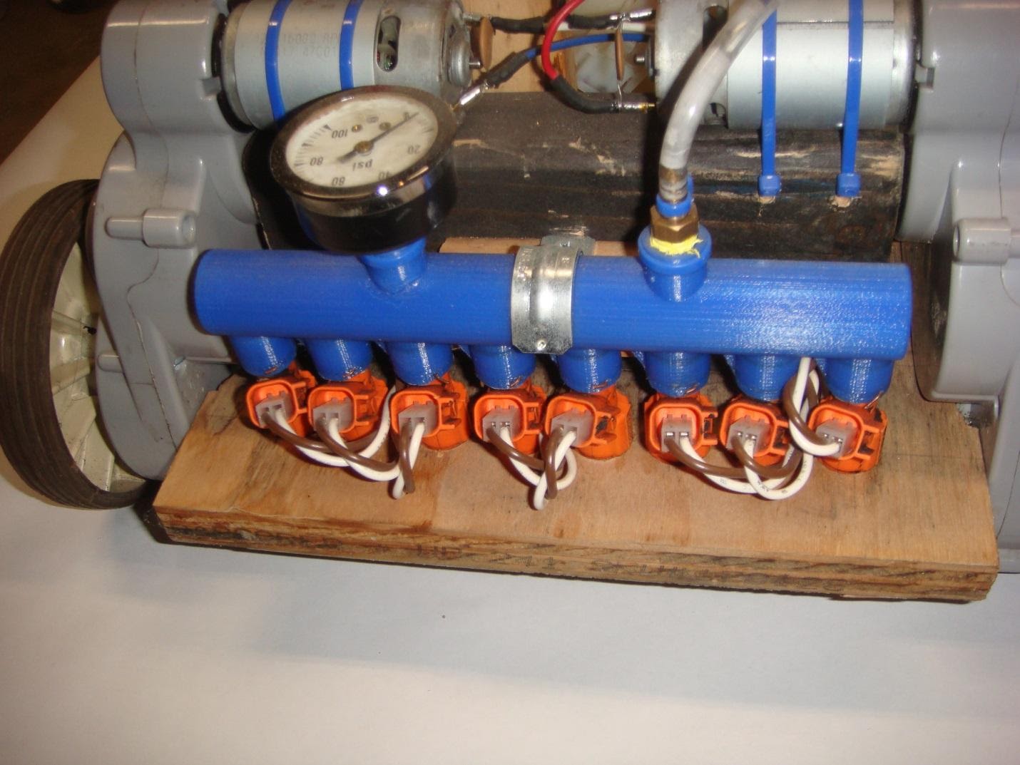
I bought 8 used fuel injectors and then designed and 3D printed a manifold to fit the fuel injectors on and supply water (see the orange injectors on the blue manifold).
Fuel injectors are great for this project. Each fuel injector contains a valve to control the flow of water, a 12V electric solenoid to control the valve, a nozzle that sprays water in the controlled area, and a plumbing and seal to supply water to the valve and nozzle. All internal metal parts are made of stainless steel, so the fact that we use water and not gasoline does not cause corrosion problems. To shorten the length of the printed water pixel a little, you only need to have the Arduino apply a 12V pulse to the solenoid for a short period of time.
I designed the manifold so that the fuel injectors are spaced far enough apart in order to position their pixels out of the water next to each other. If your fuel nozzles spray water in a very different way, you may need to adjust (raise or lower) the height of the manifold / nozzle assembly so that the nozzles are in close proximity.
I have found a few non-standard connectors with wires that are suitable for mounting on the fuel injector pins, but you can use the original car connectors for this. For more information on connections, see Step 10 - Final Assembly.
Used fuel injectors were purchased on Ebay, for about $ 2 each
(translator's note: you can buy similar injectors at your nearest car dealer. Special connectors for these injectors are also sold there. For example, here . It is recommended to use standard injector / connector kits with wires, since shaking while driving can cause inconvenience - constant loss of contact.)
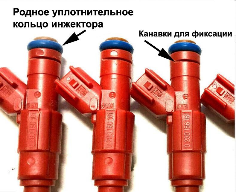
It seems that similar parts are available for different types of cars. The accompanying photograph highlights important features required to operate the injector with the manifold design shown here.
- O-ring at the top, sealing the nozzle / manifold junction;
- , ( );
The 3D printed manifold is the most challenging part of this project.
It contains 8 fuel injector sockets, pressure gauge holes, water inlet and must be waterproof.
I designed this part in TinkerCad and it was pretty simple. I am attaching STL file and Gcode file for PLA. Also watch the video showing the TinkerCad model and 3D printing (took 8 hours).
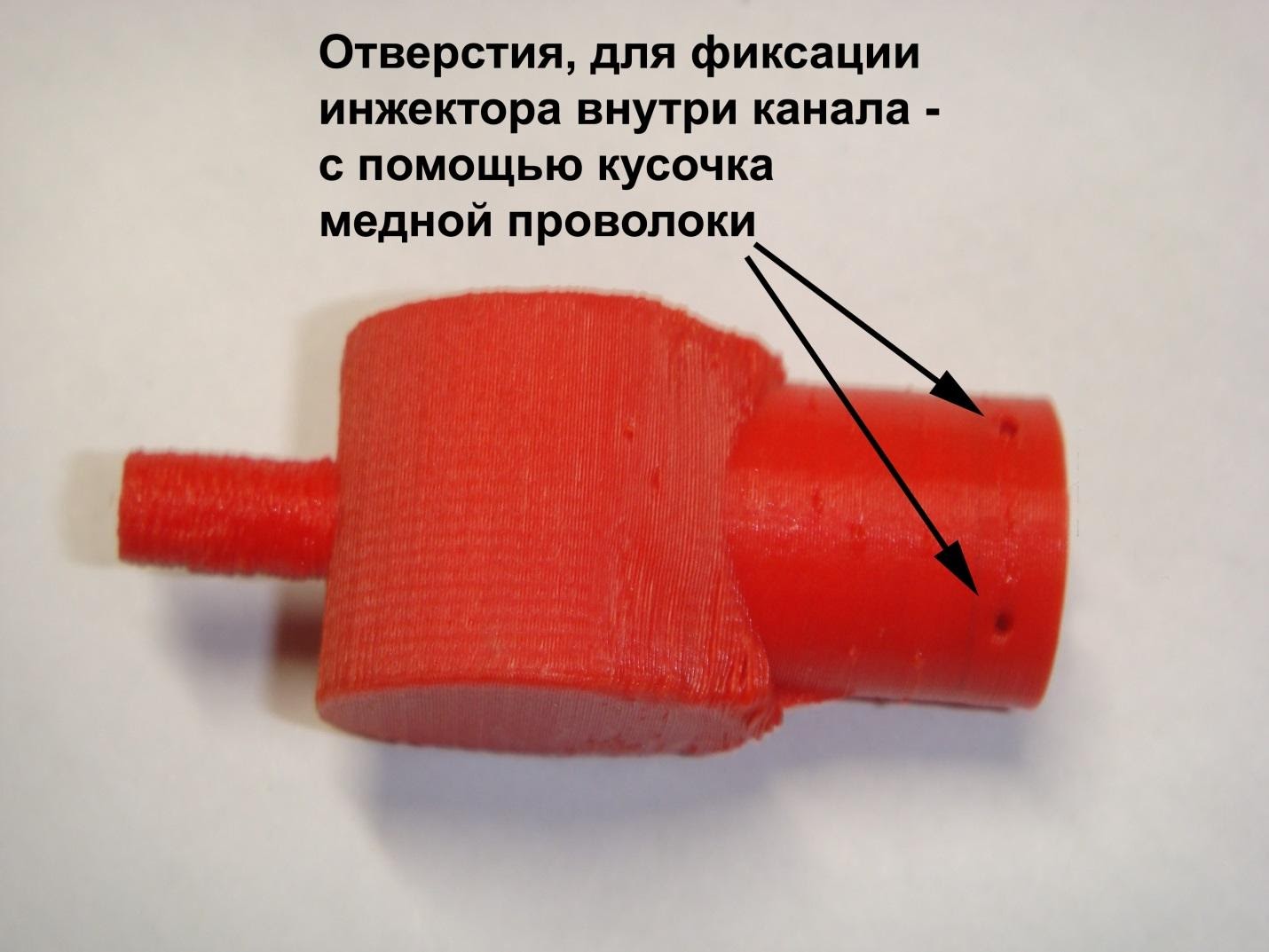
One of the images of this step shows a small red section of the manifold showing the holes used to hold the fuel injectors in the manifold. I simply passed a piece of copper wire through the four holes and the fuel injector locked into place.
The main purpose of this little piece was to check that the injector fits into the bore and make sure the assembly is waterproof before proceeding with the 8 hour assembly. I clamped the part in a vise with a piece of rubber across the open end and pumped water under pressure - the water was leaking. I modeled this part several times with different settings in the Cura slicer and could not get it waterproof. It always leaked in several places. In the end, I took Sli3er as a slicer program and the part passed the water resistance test on the first printout. The gcode of this version is attached here.
After the manifold is printed, there are a few final steps to be taken before it can be used.
- , ;
- 4 , ;
- 1/8 NPT .
- , , . , 3D- , . , WELD-ON 4 , , .
At this point, the fuel injectors can be installed in the manifold and secured there with pieces of copper wire.
I applied lithium grease to the o-ring on each nozzle prior to installing it to facilitate installation and ensure a tight seal.
Check the work done. Install a pressure gauge and hose adapter. Apply water pressure at atmospheric pressure and look for leaks. If you find them, you can use WELD-ON 16 glue or WELD-ON 4 thinner to seal the found and retest.
Download collector file in STL
Download collector file in Gcode
Step 3: frame, motors and wheels
As I said in the introduction, the purpose of my StreetWriter build was functionality, not beauty or looks.
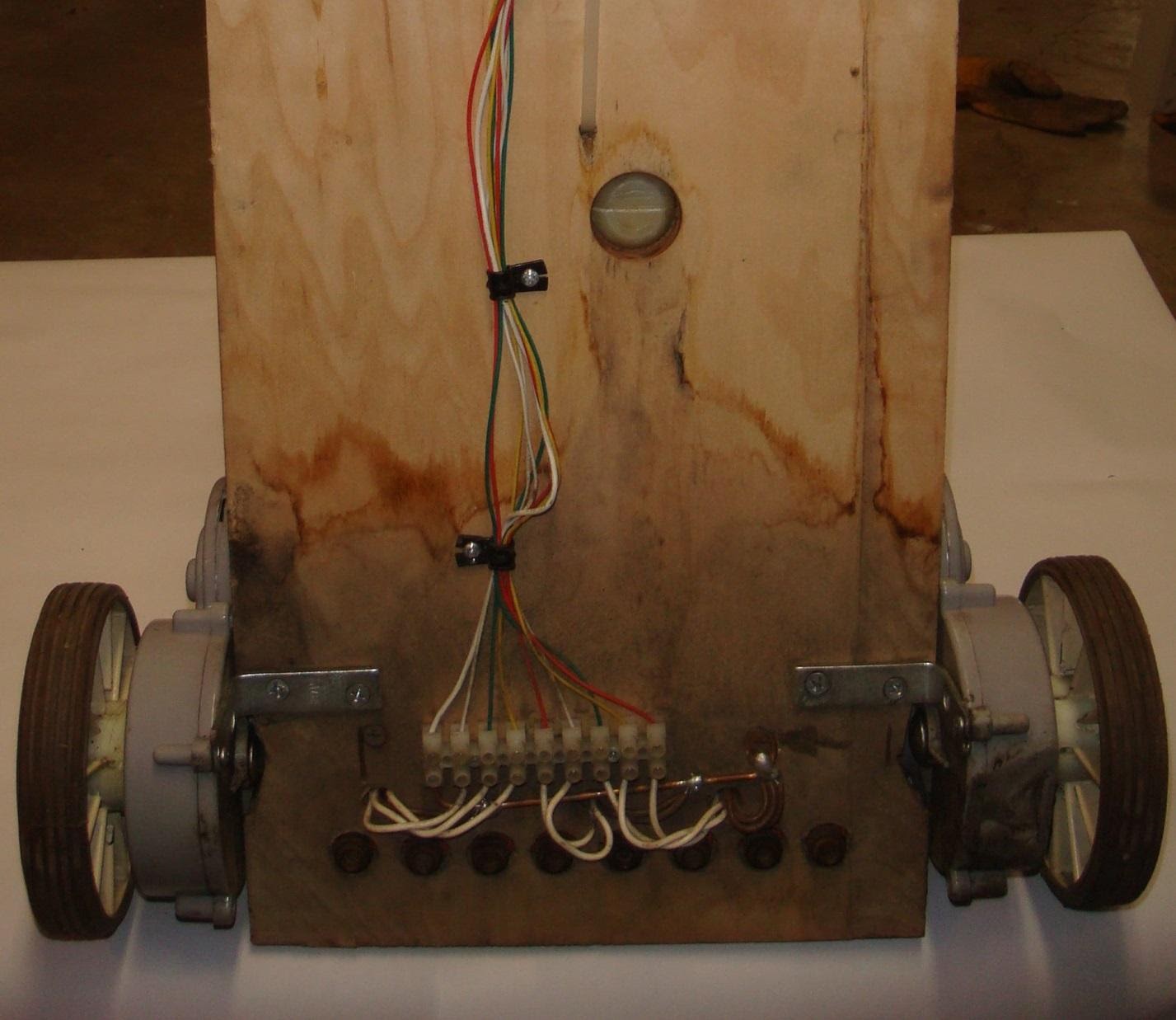
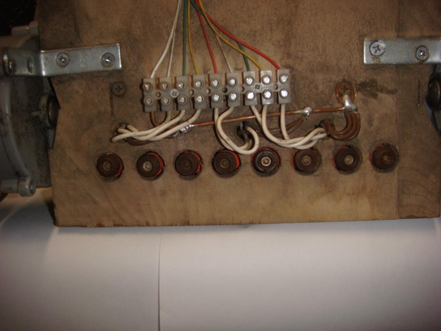
The frame is made of ½ ”(12.7 mm) plywood with holes, wood bosses, etc. added as needed. The general photo gives an idea of how everything was posted. The only important placement is the row of fuel injectors at the rear of the platform, between the rear wheels. Thus, when turning the platform - the message will be minimally distorted, and the wheels will never run over it.
The fuel injectors hang from the manifold and pass through holes in the frame. They are not supported by a frame. The manifold is on the frame and is held loosely by only one tube clamp, which you can see in the rear view photo.
The platform is driven by two wheel assemblies, which were taken from old children's Power Wheels that I had. The attached image shows similar blocks. The engines of the power plant are connected by a cable to the block on the frame and reinforced from below with L-shaped brackets. I have added 0.1uF capacitors to the motor terminals to reduce electrical noise from brush type motors. (Arduino spontaneously rebooted without capacitors.)
The movement of this platform is a “tank-type” movement, in which the power to the first or second engine is turned off for taxiing. Steering is disproportionate - stop one wheel and the StreetWriter will turn sharply. Smooth turns are performed by the operator pressing intermittently to the right or to the left while moving forward.
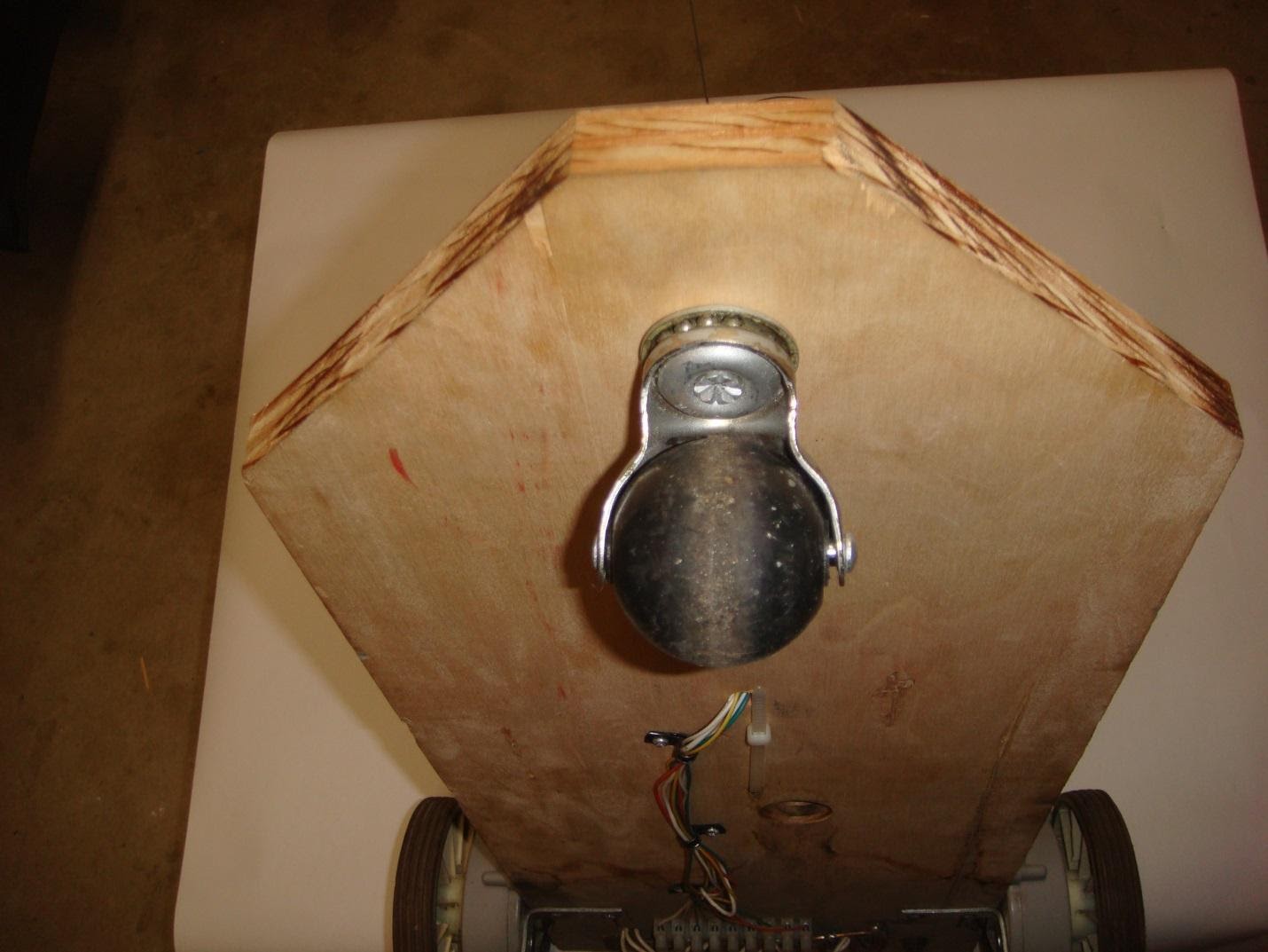
There is a wheel at the front of the frame that allows the StreetWriter to make tight turns when one wheel stops turning.
The rear wheels of Power Wheel style riders are usually connected by an axle, so both wheels rotate together.
It doesn't work here because I want the rear wheels to work independently for steering purposes.
I found 5-inch (127mm) wheels somewhere and with a few tweaks I was able to use them for business. Close inspection reveals that this particular wheel has 12 struts. The drive assembly has 6 slots. I just cut off all the other legs and the rest of the legs fit neatly into the grooves in the drive assembly. I ran the bolt through the hole that originally contained the axle and a Nyloc nut to hold them together with enough play to allow the whole thing to rotate. (Depending on what parts you use for the drive and wheel assemblies, you may have to get creative to get them to work together.)
Download StreetWriter's wiring diagram in pdf
Step 4: remote control
In keeping with the goal of using "found" parts where possible, the StreetWriter's remote control is based on electronics from a smashed small RC car. An important requirement is that the remote control must be radio, not IR, since the StreetWriter will be used outdoors. Most of these cars don't have perfect proportional steering.
They either turn right or left, or go straight.
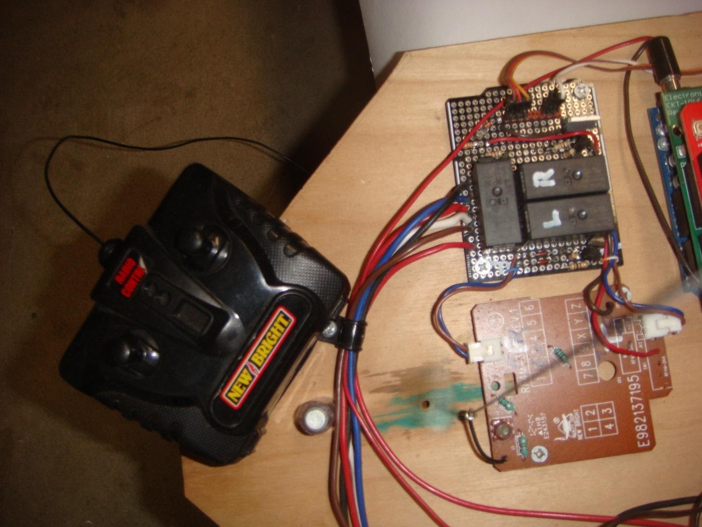
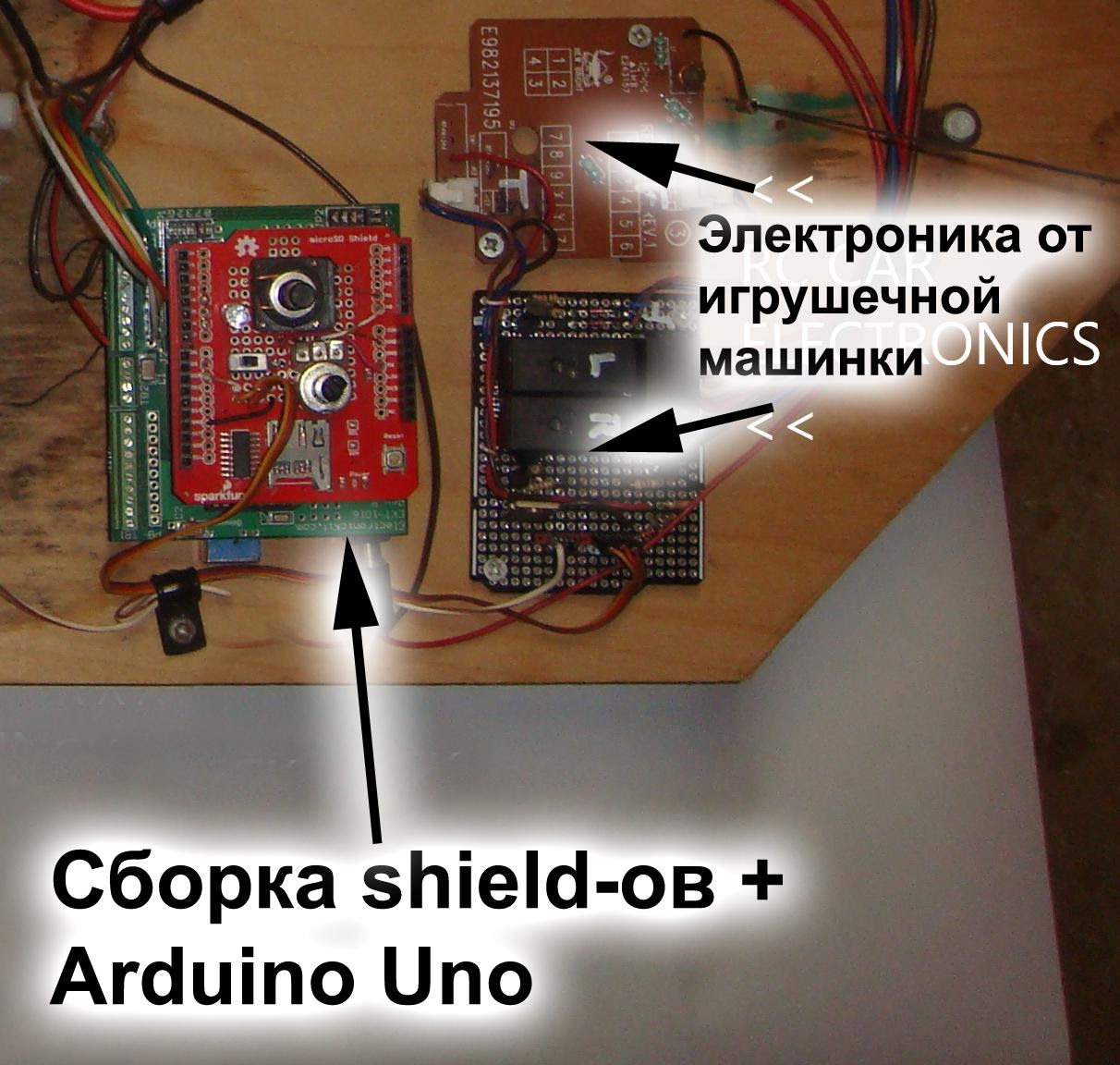
I used electronics from a toy car and added a relay to bring the power up to the level required for the drive assemblies. The bottom (brown) PCB in the picture is from the typewriter. The upper (with a trimming resistor) board contains a relay and a voltage regulator necessary for the electrical circuits of a 4.5V machine. The circuit is attached.
The circuit is pretty simple. The transistor drives each of the three relays. One relay drives the left motor, one drives the right, and the third changes the direction of power to both motors for reverse travel. Control signals come from the printed circuit board of the radio-controlled car. When a left turn signal is applied, the transistor causes the left relay to turn off, stopping that motor.
The remote control is shown in the picture.
I added a piece of music wire (out of focus in the picture) to slightly increase the range.
This circuit only has one connection to the Arduino. This connection tells the Arduino that the car is moving forward. If the car stops or moves backward, no water is sprayed out.
Step 5: pressurization system
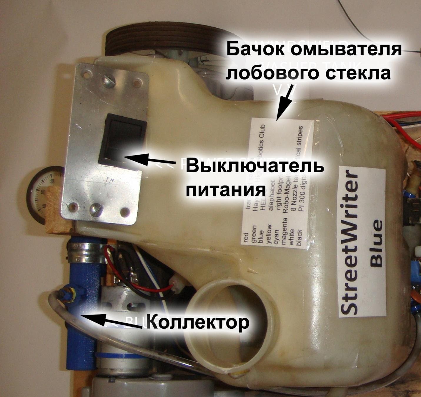
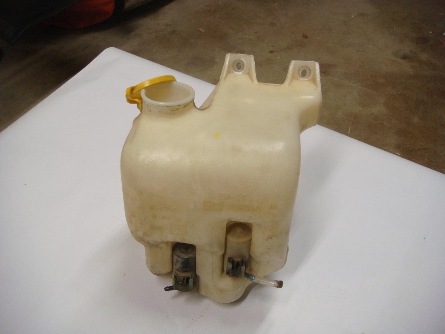
The pressurized water for the StreetWriter comes from the windshield washer reservoir from an old Subaru, but the car it comes from is not critical. Any tank with a built-in 12V water pump will do.
This particular tank contains 2 water pumps, so I just unplugged one of them and used the remaining one. There is a bulge at the bottom of the tank designed to mate with a hole in the car body. I just drilled a hole in the StreetWriter's frame to fit in there and screwed the top of the tank to a wooden beam on the platform. Then I used the bolts to attach the plate with the main power switch.
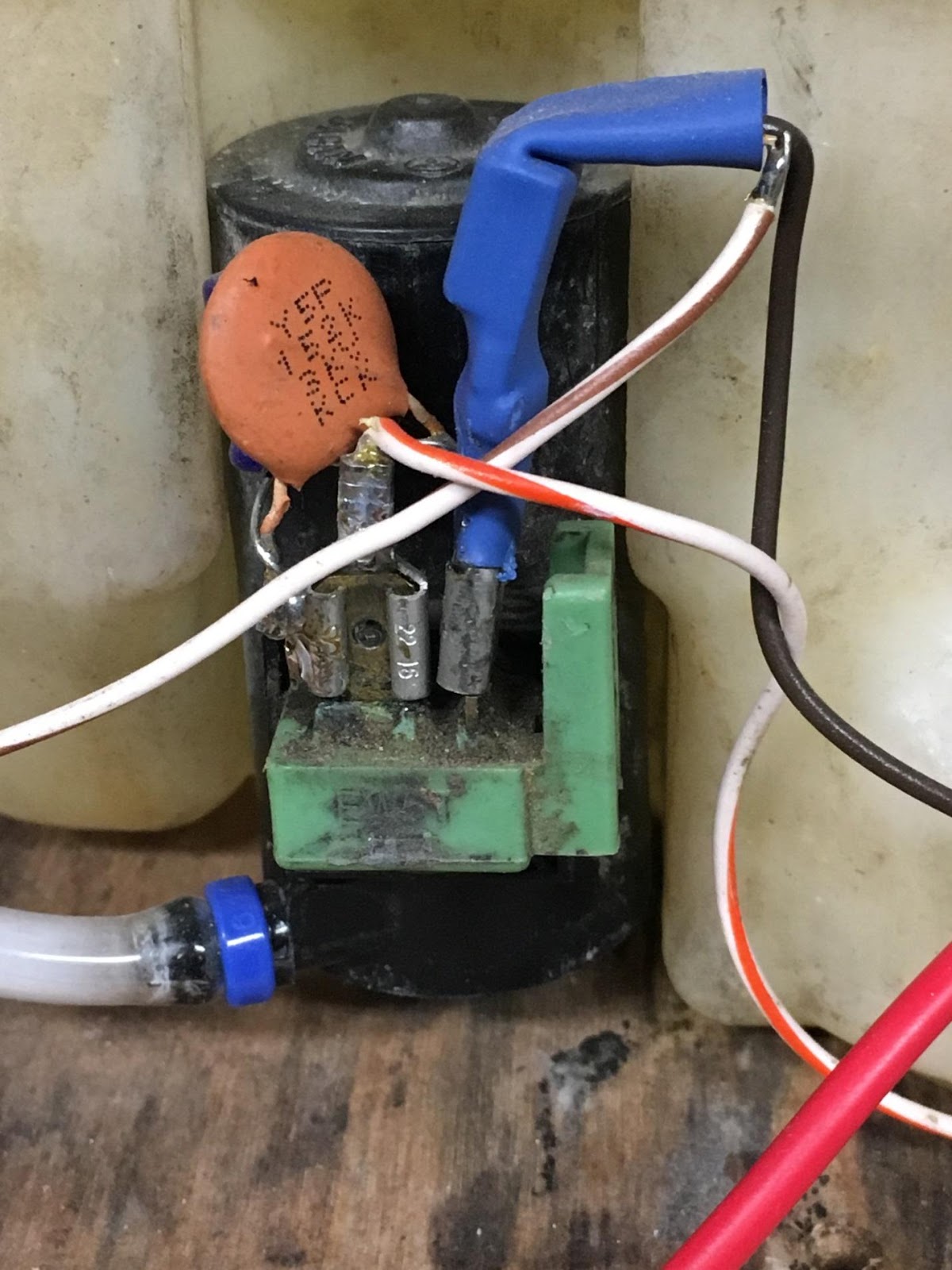
The pump motor requires more power than the Arduino output can provide. A transistor amplifier is installed on the pump itself to reduce electrical noise. (see control diagram and rather ugly wiring image).
The tubing runs from the pump on the reservoir to the nipple on the manifold. The nipple is sized to fit tubing and 1/8 in. NPT threads on the manifold.
The Arduino code briefly starts the engine before allowing the fuel injectors to print to build up pressure in the system.
The Arduino code also triggers the pump when you twist the pressure change knob so that the user can set the manifold pressure as needed, as different surfaces require more or less water for good readability. You just turn the knob and the pump starts up, so you can adjust the pressure with the pressure gauge. When you stop turning the handle, the pump turns off.
Step 6: Arduino Shields
StreetWriter requires two shields besides the Arduino Uno.
The first one, EKT-1016, is the one I bought from Tindie.com. It provides the ability to use 16 channels. In this project we are using 8 of them.
The second shield was obtained from SparkFun (www.sparkfun.com/products/12761).
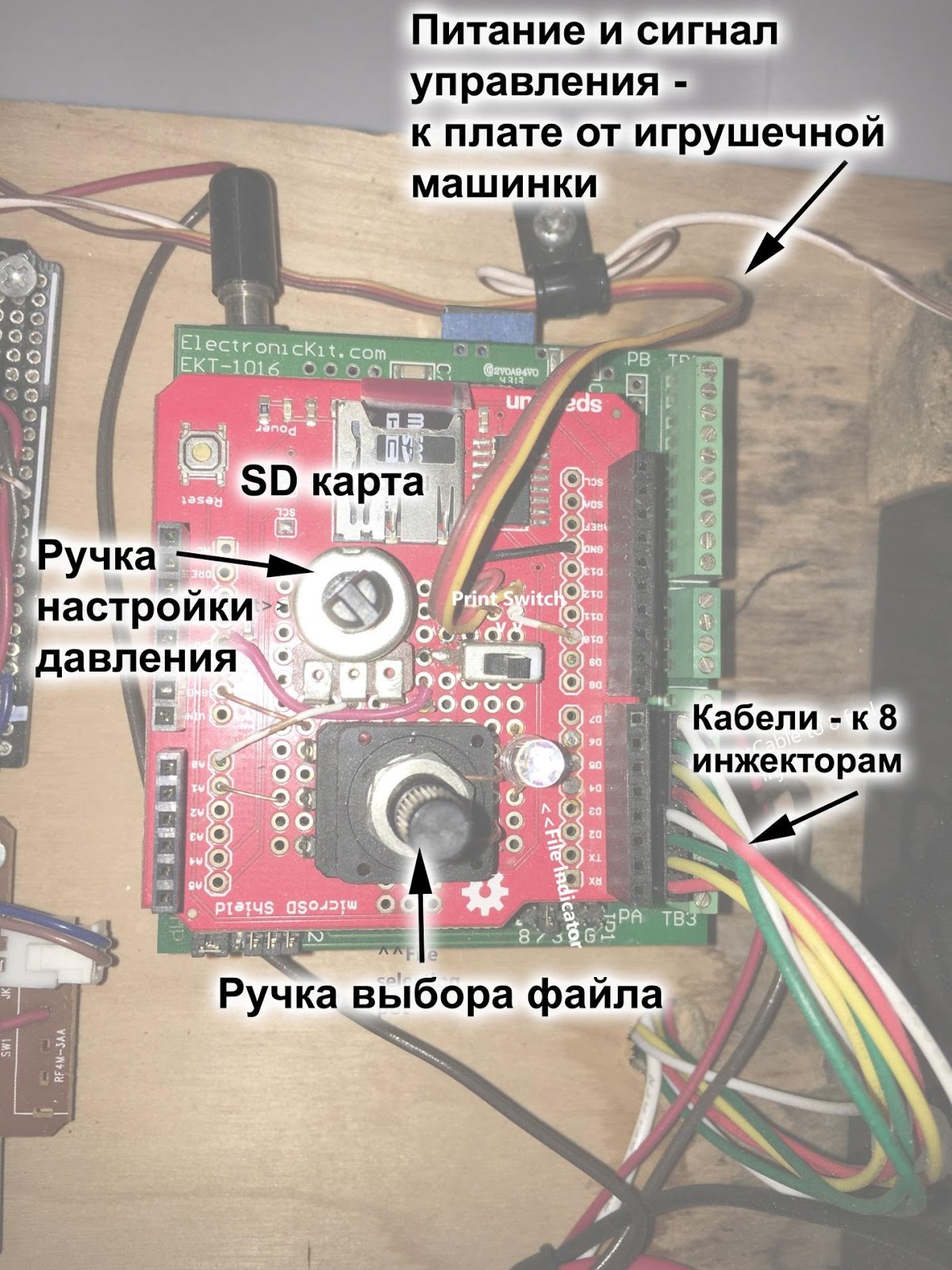
It contains an SD card reader and several additional options:
- potentiometer for adjusting water pressure;
- a potentiometer for selecting a text file that the StreetWriter will write;
- multi-color LED showing which of the 8 files has been selected;
- switch to disable printing when moving forward;
- connector for grounding and two necessary signals: a " forward" command and a "pressure" command to the pump.
Download the StreetWriter wiring diagram in pdf
Step 7. Font letters and font design
The main function of StreetWriter is to use a digital font to create symbols.
Luckily, someone did all the hard work of creating the fonts and provided us with the results here .
This font editor program has several font samples available, giving the user the ability to edit these existing fonts.
You can then output the resulting font as a block of code that you can put directly into your Arduino program.
I changed one of the fonts to add footprints and this file is attached (footprintFONT.pf). You can use any of the sample fonts that come with the pixel font, or the one that comes with it, to create the block of code that the Arduino firmware needs.
Download font file
Step 8: text files
The next step Arduino code allows you to read and print one of 8 text files.
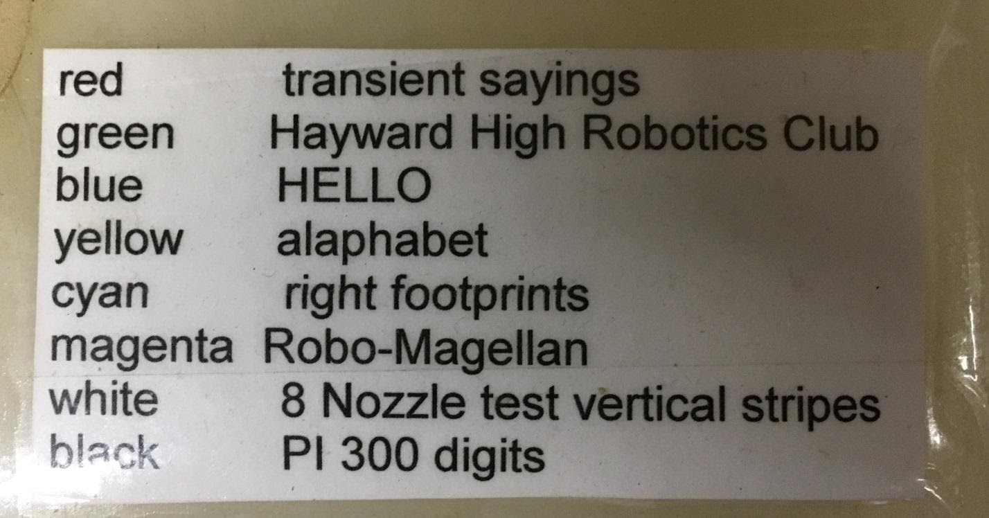
Which file will be printed is selected with the rotary knob on the Arduino shield and is indicated by the LED indication (different colors). Colors: red, green, blue, yellow, cyan, magenta, white, black.
The text files on the SD card are named with the same eight colors for easier identification. The text in the file has nothing to do with the file name.
I usually put the TOC.txt file on the SD card to keep track of the contents of each file, print that file and paste it into StreetWriter. (see picture)
Files can be of any length. For example, the BLACK.txt file contains a 300-character PI.
Text files can be created in any text editor, but some editors may add line breaks that affect the spacing between messages during printing. I usually use Notepad.
The Arduino program I wrote has the ability to access "non-printable" character positions in the font table by directly accessing the character location. For example, part of one footprint is in font cell 128, so the text file contains ^ 128. The Arduino code detects the "^" and uses it as the "escape character". It does not print "^", but selects the next three characters as the font location and prints that character.
(^ 128 ^ 129 ^ 130 ^ 131 ^ 132 ^ 133 prints the six characters constituting one left and one right mark.)
Download text file Red
Download text Green file
download text file Blue
Download text file Yellow
Download text file Cyan
Download text file Magenta
Download text file White
Download text file Black
Download text file CONTENTS
Step 9: Arduino Code
The Arduino code for this project is attached. There are a few things worth mentioning, however.
The program has two tabs. (In order for the Arduino IDE to find and use these files, they must be placed in a folder named STREETWRITER_BLUE.)
STATESET is simply a procedure that interacts with the ETK-1016, including its drivers and therefore the fuel injectors.
STREETWRITER_BLUE is the main routine where everything else happens.
Starting on line 13, there is a very long array:
const uint8_t font [] PROGMEM = {
0x00, 0x00, 0x00, 0x00, 0x00, 0x00, 0x00, 0x00, // Char 000 (.)
0x7E, 0x81, 0x95, 0xB1, 0xB1, 0x95, 0x81, 0x7E, // Char 001 (.)
…
0x44, 0x6C, 0x38, 0x10, 0x38, 0x6C, 0x44, 0x00, // Char 120 (x)
…
0x00, 0x60, 0x40, 0x40, 0x40, 0x40, 0x60, 0x00 // Char 255 (.)
};
This is the font table. Each line describes one character and ends with a comment, which indicates the address of this character and its name. Non-printable characters are indicated by (.). This table is too large to fit into the Arduino's working memory, and the compiler directs it to flash memory. This is fine, as the table is only read and not written while the Arduino is running.
The main loop starts at line 345. It determines that the StreetWriter moves forward, reads the next character from the open text file. It sends the bytes of this character to the fuel injectors one stroke at a time. Then it picks the next character and sends it.
On line 347:
The Arduino does not control how long the letter bit splashes water when the StreetWriter speed changes. In practice, I've found that StreetWriter's speed is fairly consistent, so testing once and adjusting the stroke width during setup is enough to get a good enough result. In this code, you can see that it is set to 500.
Pulsemin, Pulsemax and Pulse are the values that worked for my implementations.
Line 376 has a code that starts the pump for ½ second to allow the operator to check and adjust the pressure. As long as you rotate the handle, the pump will run. When you stop its rotation, the pump, accordingly, will turn off.
On line 393the code checks which font character was returned from the text file and decides how to print it.
The UNPACK routine on line 403 unpacks the font bytes and sends them to the fuel injector drivers.
The COLOR subroutine on line 410 checks the position of the file select potentiometer, turns on the corresponding LED color, then opens the corresponding text file.
Download streetwriter_blue.ino file
Download stateset.ino file
Step 10: final assembly and adjustment
I have not provided a general connection diagram, but it is simple.
- shiled-. , , . , shield-. (shield );
- shield- — Arduino, . 4- , shield- ( );
- : , Arduino . , ( );
- The cables between the radio control board and the mini platform board carry power and signals forward / backward, left / right.
Let's check if it all works?
- Are the motors connected to drive forward when the remote is sending a forward command? Otherwise, swap the wires to the engine (s).
- Does the pump start and can its pressure be adjusted?
- Do all fuel injectors work when you command forward? I like to use a test pattern (white.txt) which should draw 8 stripes.
- Does the file selection potentiometer change which file is currently being printed? Do the files match the color of the LED?
- Is the letter wide enough? If the letters are too narrow or too wide, you must change the stroke width in the Arduino code, it is now set to 500.
Step 11: improvements
Since the StreetWriter described here is the second build, some improvements over the first build are already included.
The biggest changes:
- use a windshield washer reservoir, not the garden sprayer you can see in the video;
- Using EKT-1016 instead of dedicated wiring for power amplifiers.
I was thinking about creating a 12-16 pixel version to get a higher resolution in the written text, but could not find a software source like Pixelfont for a higher resolution, and I am too lazy to write this from scratch. Please let me know if you do such an assembly.
I have been asked to use paint or some other liquid that is more resistant than water, but I resist. The fleetingness of what StreetWriter does is part of the idea.
I have tried adding kitchen detergent to the water to see if bubbles appear during printing. As a result, I had weak, clean patches in my driveway, with readable messages that lasted for several months. No bubbles.
In addition, it turns out that the implementation of this idea on a larger scale was developed in parallel: www.trikewriter.com Translator's
note: this project was implemented by the author some time ago, so it does not use the latest opportunities that the market gives us at the moment ... At this time, the most rational implementation of this system seems to be using the esp32 board, this will significantly simplify many details of controlling this system and use a smartphone as a control panel.
, , 2 , — , - . , . , , — .
In addition, you can give the system new properties by installing an accelerometer / gyroscope board on it or simply reading pulses from an encoder installed on one of the wheels. This installation will allow you to mount the entire printing system with water, on any fast-moving device, for example, an electric scooter, which will allow you to easily and quickly apply long inscriptions while driving. Automotive injectors are designed to operate at high frequencies and will do the job well.
Macleod VDS servers are fast and secure.
Register using the link above or by clicking on the banner and get a 10% discount for the first month of renting a server of any configuration!