
Electronics surrounds us at the moment from all sides and for us it is self-evident that any complex systems, one way or another, include electronic components.
This became especially pronounced at the moment when miniature complex electronic circuits appeared, placed inside compact cases - integrated circuits.
However, this was not always the case. Due to the fact that previous generations were forced to settle for more cumbersome electronic solutions, some solutions were impossible in principle, even such a complex system as television was presented in a mechanical form !
Of course, from the point of view of our modern moment, it seems incredible that television can be mechanical - for a modern person it does not even fit in the head!
However, there was such a page in the history of displaying and transmitting information. Although, if you think about it, this is not so incredible, - if you remember, even the well-known cinema is a mechanical system! Moreover, in cinematography, not only images are applied to the tape, but also the sound is optically encoded directly on the film.
Mechanical television was based on an invention called the "Nipkow disc".
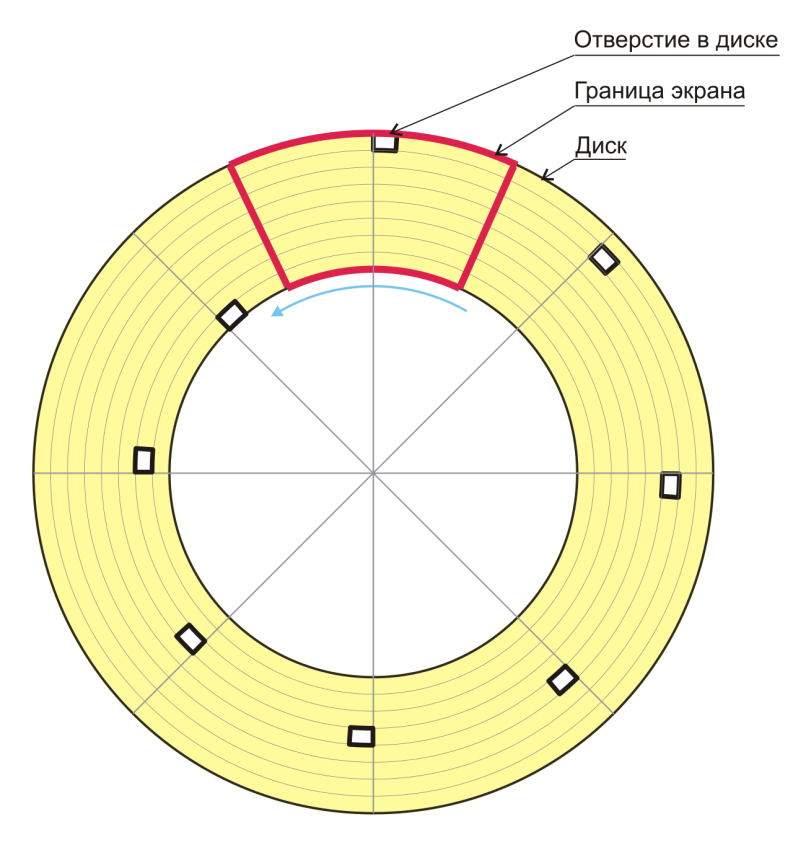
Figure 1: Nipkow disk (according to wikipedia )
This disk was made of an opaque material, along which, at equal distances from each other, holes were applied along a circle, converging to the center of the disk in a spiral - holes.
When this disc rotates, if the field of view is a narrow sector in the region of 90 degrees or less, then it is clearly visible how these holes run through this sector, as if scanning it, line by line. It was on the basis of this principle that mechanical television was built.
In short, it worked as follows: the image captured by the camera lens was projected onto a sector of the disk. The rotating disc scanned the resulting image line by line. Directly behind this disc was a photodetector that received the resulting image. Thus, it can be said that the image was scanned and encoded for transmission to the receiving device.
The receiving device, in turn, was a light source connected to a radio receiver, as well as a synchronized and rotating Nipkov disk at exactly the same speed as the disk in front of the camera.
The light source receiving signals from the radio receiver flickered at a certain frequency, which made it possible, looking into the same sector, located directly behind the disc, to obtain encoded images taken at the transmitting end.
Despite the fact that the horizontal resolution of this scanning method was rather high, the vertical image was very limited and consisted of a number of lines.
The situation was especially complicated by the fact that the number of lines in different standards was different. In addition, the devices based on the Nipkow disk were rather bulky. However, despite all their shortcomings, this was already a significant breakthrough and people of that time sincerely admired such an achievement of science and technology.
Some even create quite working instances, even now:
Over time, this principle was replaced by a more promising electron-beam scanning principle, which copied the original principle underlying the operation of the Nipkow disk - obtaining an image using its line-by-line drawing. It was on the basis of this approach that all further televisions and screens with a cathode-ray tube worked.
It would seem that all these events at the moment are already perceived as some kind of curiosity from the distant past. This is especially true of the younger generation, which did not find cathode-ray tubes and spends all their lives surrounded by electronic flat monitors.
However, despite such impressive achievements of modern science and technology, there is still one area where imaging is still carried out mechanically! Moreover, this principle is not going to die and yield the scene to other principles of image construction!
Perhaps many have already guessed what will be discussed now, However, if not, I will tell you that we will talk about DLP technology.
This technology is the property of Texas Instruments, which is a world leader in the manufacture of devices based on it. The abbreviation DLP stands for Digital Light Processing, that is, "digital light processing".
The invention of this micromirror chip was completed in 1987 by Larry Hornbeck.
Until that moment, the company had been developing in the field of micromirror systems, only they differed from the current breakthrough version in that the company tried to make flexible micromirror assemblies. And after this key moment, I began to deal exclusively with arrays of hard micromirror systems.
This technology is a truly amazing fusion of modern advances and mechanical approaches. And for those who have not yet encountered this technology or have come across, but were not deeply interested, the following information will be as interesting as it is surprising.
DLP technology is based on the concept of microelectronic mechanical devices.
The essence of these systems lies in the fact that modern technology makes it possible to produce not only miniature electronics that amaze the imagination, but also miniature mechanical devices, the cost of which is quite low and allows anyone to have access to such technologies.
These micromechanical devices are produced, as a rule, using the photolithographic method. Among such devices, one can name such widely used components as gyroscopes and accelerometers.
The physical basis of DLP technology is a DMD chip, which stands for Digital Micromirror Device (digital micromirror chip).
This chip is a square matrix, which consists of separate miniature squares - movable mirrors.
Each mirror is made of aluminum alloy and has a very high light reflectance. Each mirror can be tilted 20 degrees to one side or the other.
To perform these movements, electrostatic actuators are used, which, due to Coulomb forces, deflect the mirror when voltage is applied. The deflection rate is very high, in the order of 11 microseconds.
Due to the miniature size of the mirrors, when creating these chips, the company had to go through a number of technological difficulties, among which the main ones were mirrors sticking in one of the extreme positions. This is due to the fact that with such miniaturization, objects begin to attract each other.
To solve this problem, the company had to apply special spring stops and lubrication of the contacting surfaces after the final assembly of each chip was made.
So, we have come to a description of the very principle of operation of this system: a light beam from a source, through a lens system and an optical waveguide (to create a uniform light flux) is directed to the DMD chip. Each mirror in this chip deflects, casting a beam of light either into the projector's output lens or onto a special dark plate called a "trap." If the mirror has thrown a ray of light into the lens, then on the screen we see a glowing pixel. If the mirror was turned towards the trap, then a black dot is formed on the screen.
As we said earlier, the mirror can be deflected from one position to another with great frequency; moreover, it is rather difficult to keep the mirror in any of the fixed states, so it is forced to oscillate. By changing the oscillation speed of the mirror, we can adjust the brightness of each specific pixel in the image, as a result, and the entire image as a whole.
However, this way we can only get a black and white image. How, then, is a color image obtained? Everything is very simple - in order to color a ray of light thrown towards the screen in any color, it is enough to put an appropriate light filter in its path.
In modern video projectors, this filter is a color wheel. As a rule, these filters support the standard RGB model and consist of three colors: red, green, blue. In some projectors, to increase the brightness of the image, this wheel also contains a transparent sector.
However, this is not all! Passing rays of light through the corresponding sector, - you can get only a pixel of three of the possible colors. How, then, can you get mixed colors? I think everyone has already guessed: you just need to "blink" a ray of light several times through the corresponding sectors, for the same pixel!
Despite the fact that the colors are displayed one after the other, due to their rapid change, the brain perceives this change as a uniform color! In this way, millions of colors can be produced.
The technologies on which the production of DLP chips is based allows them to be produced with such quality that they withstand an MTBF of up to 15,000 hours or more (according to open sources).
In modern video projectors, this design is already gradually moving away: instead of a color wheel, several separate light sources are used. As these sources, both super-bright LEDs and lasers can be used. In the case of using laser radiation, the image is juicy and consists of natural delicate shades. The author of this article uses one of the projectors, which contains a laser light source and its image is distinguished by all of the above qualities.
In recent years, even more interesting types of projection systems have appeared, which contain the so-called scanning MEMS mirrors.
This device is a mirror that can be deflected in 2 planes, due to which, if a beam of light is directed on the mirror, this beam can describe an arbitrary trajectory.
A good presentation of these devices is shown in these videos:
If you use these scanning mirror systems as a scanning system to create an image, then, in fact, these mirrors can play the role of a cathode-ray tube in previous types of monitors. That is, the image is also built, running line by line.
Such systems are based, as a rule, on laser light sources, which makes these projectors quite miniature. For example, a typical projector is the size of a modern smartphone!
The MTBF of this type of scanning mirrors is in the trillions of bends of the hangers (on which this mirror is fixed).
A special advantage of this type of projection system is that the use of a laser beam allows you to get a clear image on any curved surface. That is, it is possible to project an image not only on flat screens, as is usually done in cinemas or video projection systems, but on absolutely any surface - corrugated, curved, arched, etc.
Despite the fact that the image is simultaneously located on different parts uneven, curved screen - it is absolutely clear and sharp.
The first device of this type was the Microvision ShowWX projector:
Currently, there are models from other manufacturers. For example, Celluon Picopro:
Or Nebra Anybeam:
In addition, this property of the selected projectors allows them to be used in a very interesting quality - when they are attached to a simulator of weapons and conduct a virtual battle in a dark room. This application looks like an interesting alternative to 3D glasses:
At the end of this article, we can say that, despite the widespread penetration of various electronic technologies, mechanical methods of creating an image are in no hurry to leave the modern world. Who knows, maybe in the near future we will see some more impressive application of the symbiosis of mechanics and electronics?
Macleod VDS servers are fast and secure.
Register using the link above or by clicking on the banner and get a 10% discount for the first month of renting a server of any configuration!