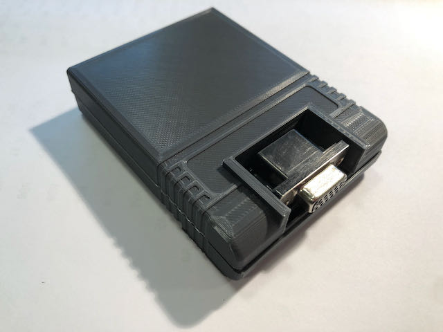
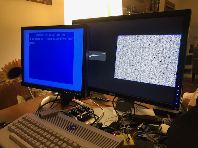
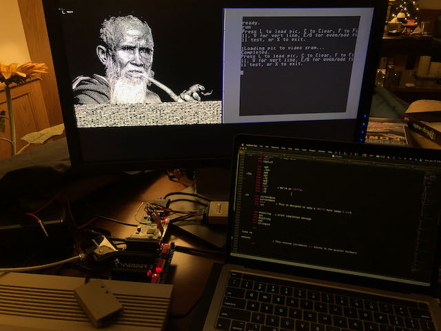
After coming up with the idea of adding a second display to the Commodore 64, I quickly implemented this project. All the hardware fits into a standard size cartridge (including the DE-15 connector). Video output compatible with VGA (31 kHz).
Inside the cartridge is 128KB SRAM for the framebuffer and a simple 1-bit DAC.
TL; DR
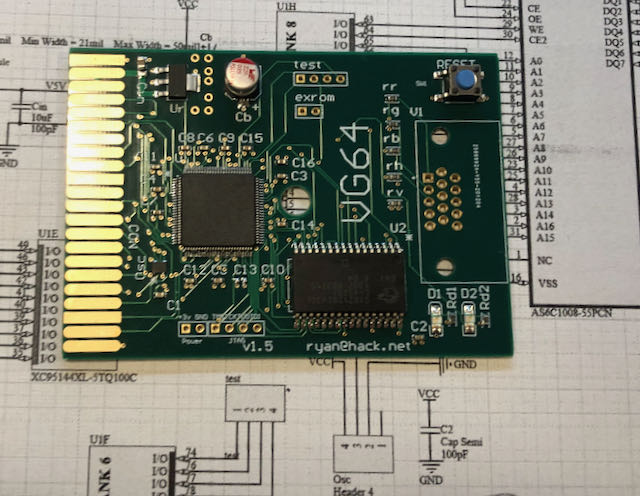
This is what the board looks like inside the cartridge. You can download the source here .
Programming interface
The cartridge can be placed anywhere in the 64KB address space, including I / O1 or I / O2. There is Verilog code to present either in a window in the @EXPROM framebuffer, which will take up 8KB of Basic memory, or a register-based approach that saves RAM.
In the examples shown, I / O1 at $ DE00 is used for the control registers. You may want to change the example provided if there is a conflict with some other addon (second SID chip, etc.). In general, there is support for a special token that allows you to avoid conflicts, but I do not have additional software that causes these conflicts. IOBASE
registers
= token
IOBASE + 1 = lsb address
IOBASE + 2 = msb address
IOBASE + 3 = data The framebuffer
is linear and easy to use, like the native C64 bitmap modes. At SRAM, it starts at $ 00,000.
Video output
Regardless of the selected mode, video is output with a pixel rate of 25 MHz thanks to the built-in 100 MHz generator. This parameter is close to the 25.175 MHz standard for a 640x480 screen at 60 Hz FPS. Accordingly, any display I connected showed the image correctly and without problems. The vertical and horizontal sync and blanking areas are set to the correct polarity and length to trigger this mode. There are two possible interpretations of the framebuffer data: high resolution 640x480 1 bit per pixel and multicolor low resolution 320x480. Both modes are palette direct.
Iron
The hardware is pretty basic: 3.3V regulator, CPLD, oscillator and SRAM. SRAM spends half of its time responding to the host and half of its time loading pixel data. The CPLD used here, the Xilinx 95144XL, is 5V stable, so it sits on the C64 expansion bus, although it is powered by a 3.3V regulator along with the rest of the hardware.
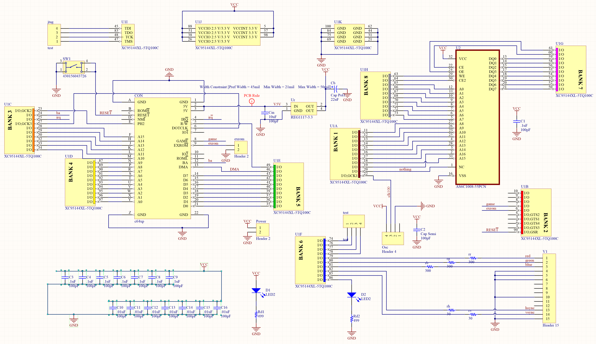
Almost all CPLD resources are used. I was hoping to put one hardware sprite for the pointer, but there just wasn't room for that.
For those who will print coolers, the STL model has everything you need, and in the C64 style.
The important point is that you need a JTAG programmer to load the bitstream into the CPLD.
And one more thing - the cartridge does not work with the Ultimate 64 board. Moreover, installing a cartridge on this board may damage the cartridge. But everything works with all versions of C64, C128 and C64 Reloaded boards. I don’t know for sure if the cartridge is compatible with all versions of the C64 or C128 released by Commodore, but I don’t see any problems.
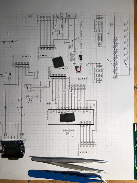
Specifications
- 4- . Gerber. , ( , female-).
- . STL.
- , 22 , 6,6
- , pn 430156043726, reset .
- .1"
- 0603: 2 499R, 3 300R, 2 30R
- 0603: 10 0,1 , 7 0,01
- 2 3,2x1,6 ( , )
- XC95144XL-5TQ100C CPLD ( )
- JEDEC 128kx8 SO Async SRAM a la AS6C1008-55PCN ( )
- VGA , DE15
Verilog
I used Xilinx ISE 14.5 because I could not find an open source toolkit for these CPLDs. If anyone has such information, please share.
Pixel packing
In high definition mode, each bit corresponds to one pixel. 1 = white, 0 = black. Addresses move from (0,0) at the top-left most visible position to the bottom-right (639 479), column by column, then line by line. Bit 7 in each byte is the first pixel.
In multicolor mode, pixels are output at the same rate as in monochrome mode, but each color channel has a different resolution. Green is 1/2 pixel rate and red and blue are 1/4 pixel rate. The mapping of the bit pattern to the color channel is byte-by-byte (fragmentary) and is:
G0 G1 G2 G3 R0 R1 B0 B1
While the screen representation of each byte of the frame buffer looks like this:
R0 R0 R0 R0 R1 R1 R1 R1
G0 G0 G1 G1 G2 G2 G3 G3
B0 B0 B0 B0 B1 B1 B1 B1
Convert images for display with ImageMagick, monochrome mode:
convert input.tiff -resize 640x480 -colors 2 -depth 1 output.mono
Color mode:
convert input.tiff + dither -posterize 2 -resize 640x480 output.tiff
convert output.tiff -separate channel% d.png
The code is written in Python - this option seemed to me the simplest:
from PIL import Image
from array import *
import numpy as np

ir = Image.open("channel0.png")
ig = Image.open("channel1.png")
ib = Image.open("channel2.png")

ir = ir.resize((640,480))
ig = ig.resize((640,480))
ib = ib.resize((640,480))

r = ir.load()
g = ig.load()
b = ib.load()

arr=np.zeros((480,80,8))
out=np.zeros((480,640))

for y in range(0,480):
        for x in range(0,80):

                # 0 1 2 3 is green level
                # 4 5 is red level
                # 6 7 is blue level

                # GREEN

                arr[y][x][0]=(g[x*8+0,y]+g[x*8+1,y])/2
                arr[y][x][1]=(g[x*8+2,y]+g[x*8+3,y])/2
                arr[y][x][2]=(g[x*8+4,y]+g[x*8+5,y])/2
                arr[y][x][3]=(g[x*8+6,y]+g[x*8+7,y])/2

                # RED

                arr[y][x][4]=(r[x*8+0,y]+r[x*8+1,y]+r[x*8+2,y]+r[x*8+3,y])/4
                arr[y][x][5]=(r[x*8+4,y]+r[x*8+5,y]+r[x*8+6,y]+r[x*8+7,y])/4

                #BLUE

                arr[y][x][6]=(b[x*8+0,y]+b[x*8+1,y]+b[x*8+2,y]+b[x*8+3,y])/4
                arr[y][x][7]=(b[x*8+4,y]+b[x*8+5,y]+b[x*8+6,y]+b[x*8+7,y])/4

for y in range(0,480):
        for x in range(0,80):
                for bit in range(0,8):

                        arr[y][x][bit] = int(round(round(arr[y][x][bit])/255))

newfile=open("output.bin","wb")

for y in range(0,480):
        for x in range(0,80):

                out[y][x] = int(arr[y][x][0] + arr[y][x][1]*2 + arr[y][x][2]*4 + arr[y][x][3]*8
+ arr[y][x][4]*16 + arr[y][x][5]*32 + arr[y][x][6]*64 + arr[y][x][7]*128)

                newfile.write(out[y][x].astype(np.ubyte))

newfile.close()
Demo video:
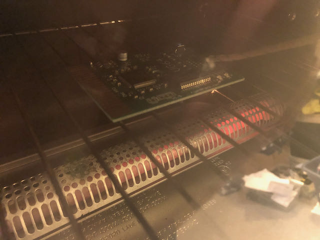
We collect and solder:
From this link you can download all the files necessary for work.
