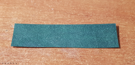
To begin with, a few words about what it is and in what cases it is used. In this case, Wikipedia rightly statesthat a flexible printed circuit board (hereinafter referred to as FPP) is such a thing that can bend freely. Can not argue. In the most common case, the GPP is used in the form of connecting stubs, as for example in the picture below:

In a more advanced version, some components are also soldered on it. Those who disassembled old CDs saw that the entire body kit of the head was made just on such a gearbox. Here's a typical example:

Here we see a place for a connector to connect to the main board of the drive and holes for laser heads, the rightmost protruding "peninsula" is most likely for an integral photosensor.
GLPs are usually made on the basis of a polyimide film with copper foil glued to it. Polyimide maintains high temperatures, which is critical when soldering and has sufficient flexibility. The people call such a basis dupont (after the name of the company that produces it). It's good when there is where you can buy it, but we will all do it like a kid.
So what do we need first? Think about technology and transfer it to something that you can easily get in your village. The main component in this case will be a heat-resistant base, on which copper foil must be glued. The glue, by the way, must also be heat-resistant. And immediately ahead of those who offer to take a Kapton tape (it is just made on the basis of a polyimide film) and glue it to copper foil - nothing will come of it. The glue does not hold thin copper tracks at all, and generally deteriorates from temperature. Meanwhile, my first version was actually based on Kapton tape, but I glued the copper foil onto a two-component UV solder mask, since it has both the necessary heat resistance and sufficient strength. It would seem - well, here's the solution! And here is nifiga. As it turned out,Kapton is completely opaque to UV and the glue from the solder mask, even after a day of irradiation, did not want to polymerize at all. Option number two, this is fiberglass, and now it turned out to be quite efficient. So we will do it.
Ideally, the fiberglass should be finely woven, which I could not get, but I did find glass mat. It looks something like this:
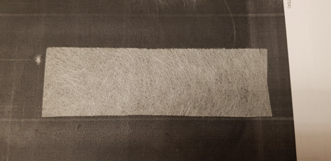
It is important to note here that it is still better to use a fabric rather than a mat, since the mat cracks noticeably at a large bend. However, this does not change the essence, which means we will work with what we have.
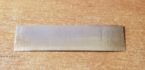
It is quite possible to use heat-resistant epoxy resins as glue, but you are a programmer, fix the coffee maker, I'm a radio amateur and I don’t have resin, but I have a solder mask. I use it. Copper foil can be bought in the form of a roll of "scotch":

Or you can peel off the PCB. It's even better to rip it off the PCB, I'll explain the reason below.
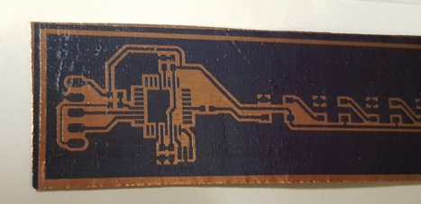
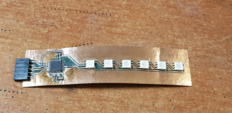
As a demo board, I threw a line of WS2812 addressable LEDs connected to the atmega328 with all the harness. The board came out like this:
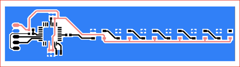
On the left side there is a connector for programming, a controller to the right, and then 6 pieces of LEDs. It is quite suitable for the test.
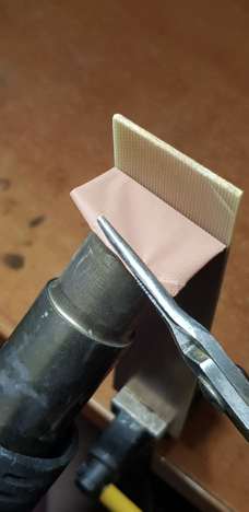
Now you need to find a victim of a suitable size and skin it off. And it's not so easy to rip it off, but I have pictures.
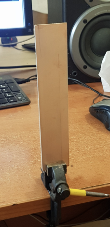
- We rigidly set the victim on the scaffold:
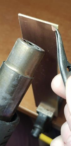
- Heat the top part with a hairdryer (~ 300C) and pick out the edge of the foil. Next, we grab it with tweezers and gently pull towards ourselves:
- Having peeled off a small piece, we turn to heavy artillery and continue to strip off the foil, simultaneously warming up with a hairdryer:

- If you continue to pull with tweezers, there is a high probability of tearing the foil. Therefore, we continue to pull with thin-nose pliers:
- A little bit more:
And ...
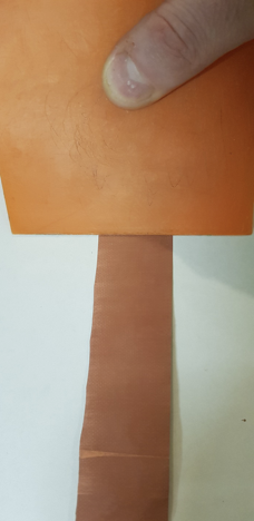
The victim now looks like this:

And the skin looks like this:

Align as in childhood, drawing an edge, for example, with a spatula, over the surface:
It is very neat here, because it is easy to leave scratches. The edge should be free of jaggies, and the surface under the foil should be absolutely flat and without crumbs.
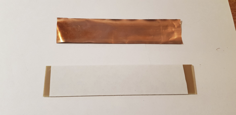
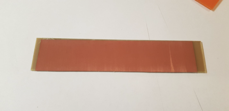
Now we try on the glass mat and trim the torn edges:

In general, the source code is ready, now we need to compile the whole thing, and there are some nuances here. First, we need to decide how we will glue. That is, just take and spread glue on foil and put a mat on top of this option. Everything will be crooked, oblique, with folds and non-glues, and the copper will most likely crumple or be remembered. It is best to stick the foil to a flat surface on three-sided double-sided tape and only then apply the glue. The same sacrifice will work as a basis. We measure, we cut, we glue:
Now, notice that I glued the foil with the back side out:
This is a point that I promised to pay attention to later. Later it came, I paid attention. What's the point? The inner side of the PCB foil has much better adhesion than the outer one, and even better than copper tape. This point is really very important because thin lines practically do not stick to the UV mask, even with good degreasing. I think everything is clear here, let's move on.
We stir the glue:
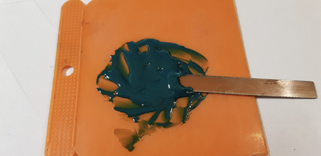
Then we smear this kaku on the foil, put a mat on top and saturate it through and through:

We smear it without regret, remove the excess with the edge of a spatula. The result should be like this:
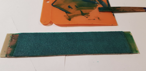
Larger:
And now the second nuance. The UV mask must be dried before exposure at fairly high temperatures and for quite a long time. But the scotch tape on which we glued the foil will not withstand such temperatures and ... uh ... well, in short, it will crumple into such a piece of shit and ruin all the work. Therefore, we do not dry for long and not much. We will dry it later.
And this is a disco with ultraviolet light, for the polymerization of the glue after pre-drying:

Then I also ran it in a hot laminator for several passes, but this is not necessary. And only now, we remove the workpiece from the base and dry it at the required temperature, the right time.
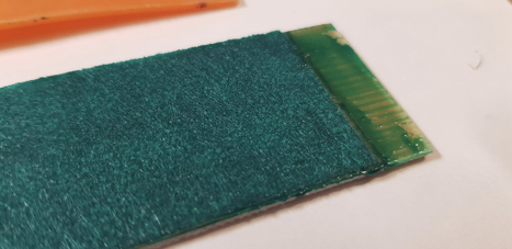
After spa treatments, Thai massage and Finnish sauna:

Circumcision:
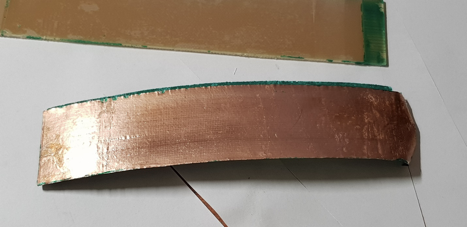
Now you can bend in all directions, make sure that the technology has not been followed and everything has stratified and throw the result into the trash. If I was wrong we continue. I have not used LUT for 5 years already, although I will not say that in this case it will not work.
I prefer photomasks:

Above is a template for a solder mask, but I decided that I would not use it, because I wanted to check how well the foil would hold on such glue. And the solder mask is like wallpaper in that joke where they do not allow a new building to fall apart. However, let's continue.
Photoresist:

I usually put the photomask directly on the workpiece, without using the pressure glass. It is best to drop a couple of drops of water onto the surface of the photoresist and press down with a template on top. Water, with its surface tension, presses the film well and

prevents it from slipping: Flare. Nothing interesting:

Unlit photoresist can be easily washed off with ordinary washing powder:

Larger:
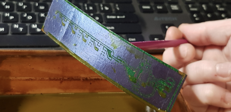
Yes, ferric chloride is dirt, red fingers, shorts, and a sink. But, in my experience, the most stable, high-quality and predictable result. And in order not to be red, I usually use a special pencil glued to the workpiece on special nano-thermo-nozzles:
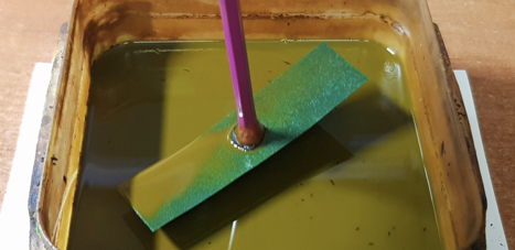
And I twist and twist the whole thing until all unnecessary copper dissolves.
Informative page
If you are using a bubble batter to mix liquids, know that you are not stirring anything at all. Air bubbles do not drive the liquid at all. This has been experimentally confirmed many times by smart uncles. And it's not about etching boards, but about more serious things. Therefore, only and only mechanical mixing.
5 minutes is enough even in a depleted solution:
It is best to wash off the remaining photoresist with a solution of hot alkali, but you can also use acetone:


The paths hold very well, and this is not only a matter of adherence to technology (high-quality degreasing, exact proportions of the mixture and the specified drying parameters), but also in excellent adhesion to the back of the foil.
Tinkering with acid:

And soldered on inactive flux:


And here is the result.
In fact, this is not the first manufacturing option. Before that, I tried to make a GPP, I use a lavsan film from lithium polymer batteries as a base. Also a working method, but the boards turned out to be too flexible, and the foil wore out quickly. The advantage of this method is that it is relatively easy to control the rigidity of the board using the right number of layers of fiberglass and better heat resistance. Suitable for prototyping.
Cloud servers from Macleod are fast and secure.
Register using the link above or by clicking on the banner and get a 10% discount for the first month of renting a server of any configuration!