Users of various interesting electronics (a couple of years ago, and I was like that) usually do not really think about the Micro-USB cables used to power their systems. I decided to make some measurements aimed at finding out how the use of different cables affects the power parameters. And it must be said that although more and more devices are equipped with USB Type-C connectors, cables for which are usually of better quality than Micro-USB cables, Micro-USB connectors are still used in the vast majority of devices. This applies not only to the Raspberry Pi, but also to other similar devices powered by Micro-USB cables (for example, these are mobile phones charged via Micro-USB).

I will immediately share my main conclusion, which is that to supply power to various electronic devices and to charge phones, it is better to use USB cables with conductors, the thickness of which is at least AWG20.
Theory
The theory behind my research is simple enough, but it's something that novice Raspberry Pi users and “regular” people usually don't think about. The fact is that each conductor of electricity is characterized by a certain resistance (that is, it can be imagined as a resistor). According to Ohm's law, voltage depends on the resistance of the conductor and on the strength of the current. As a result, for signal cables that do not carry (significant) current, the resistance of the wires does not play a special role. But if we talk about power cables and the current strength of several hundred milliamperes (or several amperes), the resistance of the conductors begins to play a noticeable role. Even if it is small, a noticeable voltage drop will occur when a high current flows through the conductor.And the voltage drop on the supply cables is simply a voltage loss that will not reach the place where it is needed. If the power supply, for example, gives out 5.0V, and because of the cable, the voltage drops by 0.3V, then the device will receive only 4.7V.
The resistance of conductors depends on the material from which they are made, on their cross-sectional area (thickness) and on their length. The resistance increases with increasing length of the conductor and decreases with increasing thickness. In order to reduce the "voltage drop" - it is necessary to reduce the resistance of the cable, for which it is necessary either to use a thicker cable than before, or a shorter cable, or a cable that combines both. The descriptions for most Micro-USB cables do not contain information about the thickness of the wires used in them. Usually they use, for all lines, rather thin conductors. But if we are talking about better quality cables, then their descriptions usually contain information about this (and for the power lines in these cables, wires that correspond to AWG20 are usually used).
Charging device
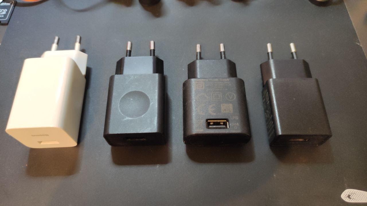
Phone chargers are often used as power supplies for the Raspberry Pi and other such gizmos. There are many types of chargers. I chose four of them - just because they were at hand, and checked how their output voltage depends on the current consumed by the devices connected to them. We are talking about the following chargers: Baseus FC67E (excellent charger), a charger that came with some Lenovo tablet, a couple of no-name chargers that were attached to some other devices. As far as I know, somewhere I had 1.5A and 2A chargers, but I could not find them.
Interestingly enough, I found that all of these chargers behave fairly consistently across the amperage range they support (I honestly didn't expect them to perform so well).
Testing methodology
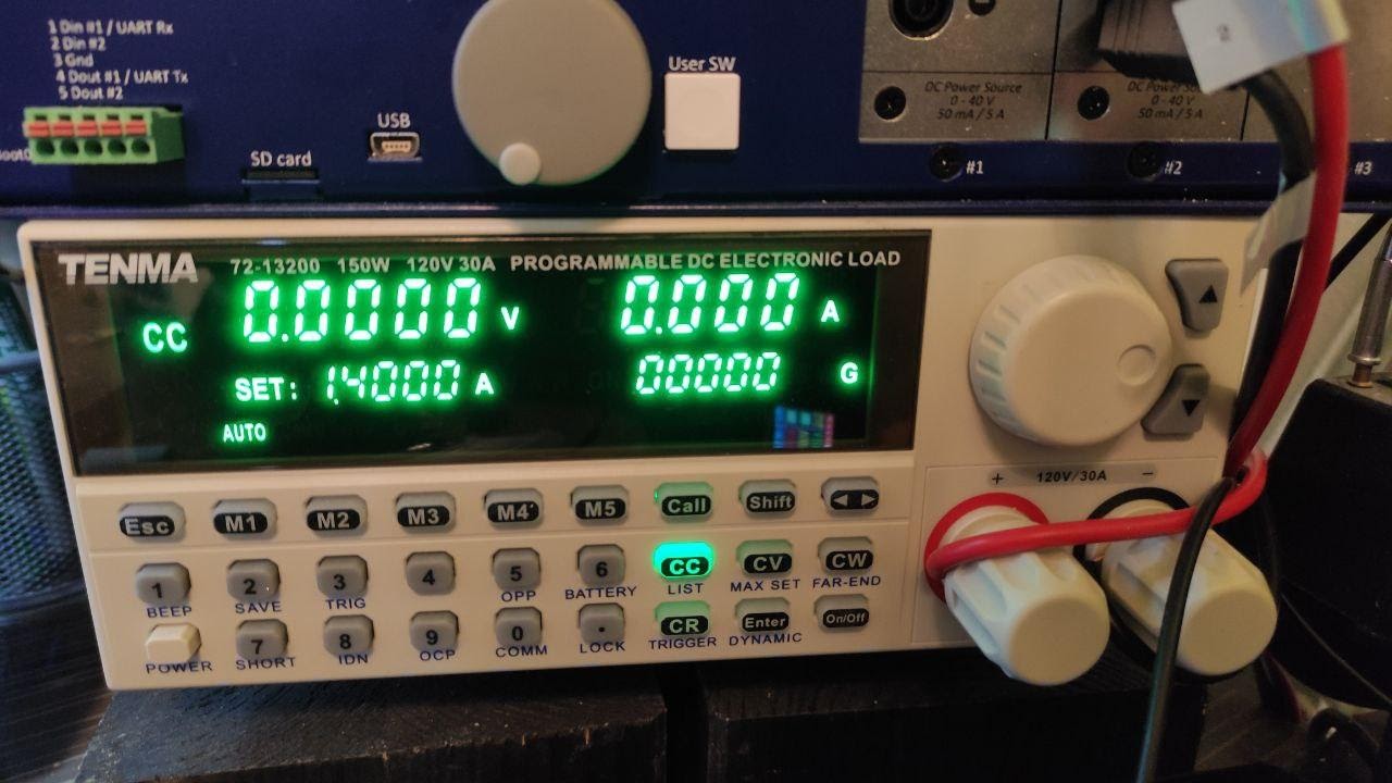
I used a TENMA 72-13200 electronic load connected directly to the USB connector (male) of the cable connected to the power supply. Some voltage drop occurs at the terminals of the electronic load, and it would be better to connect the multimeter directly to the test point, but since the test leads are quite massive, I decided not to pay attention to this fact this time (I actually forgot about it , checking the first two chargers, and then I just didn't want to take the same measurements again). And, besides, this voltage drop does not play a special role, since here I am trying only to see the big picture.
Charger test results
▍Baseus FC67E (5V / 3A, 9V / 2.66A, 12V / 2A)
| Current strength | Voltage |
| 0.0A (open circuit) | 5.057V |
| 0.1A | 5.056V |
| 0.5A | 5.056V |
| 1.0A | 5.055V |
| 1.5A | 5.054V |
| 2.0A | 5,052V |
| 3.0A | 5,048 |
| 3,4 | 5,056 |
| 3,5 | 0 () |
▍Lenovo 5/1
| 0,0 ( ) | 4,986 |
| 0,1 | 5,073 |
| 0,5 | 5,061 |
| 1,0 | 5,068 |
| 1,5 | 5,025 |
| 1,7 | 5,008 |
| 1,8 | 0 () |
▍ no-name №1 5/1
| 0,0 ( ) | 4,870 |
| 0,1 | 4,929 |
| 0,5 | 4,992 |
| 1,0 | 5,069 ( 5,06 5,08) |
| 1,1 | 0 () |
▍ no-name №2 5/1
| 0,0 ( ) | 5,075 |
| 0,1 | 4,960 |
| 0,5 | 5,073 |
| 1,0 | 5,178 |
| 1,2 | 5,240 |
| 1,3 | 4,335 |
| 1,4 | 0 () |
▍
I did not expect that two no-name chargers would work well, without a voltage drop, over the entire declared current range. In addition, it should be noted that the Lenovo charger was able to go beyond the nominal values (perhaps not for long, since I only tested the chargers for 10-20 seconds). As a result, I can conclude that the chargers I tested are quite stable (although I only conducted static tests, I did not test the dynamic characteristics of power supplies).
Cables
I found a few cables in my box of wires and took another one - the one I usually use.
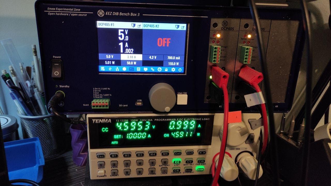
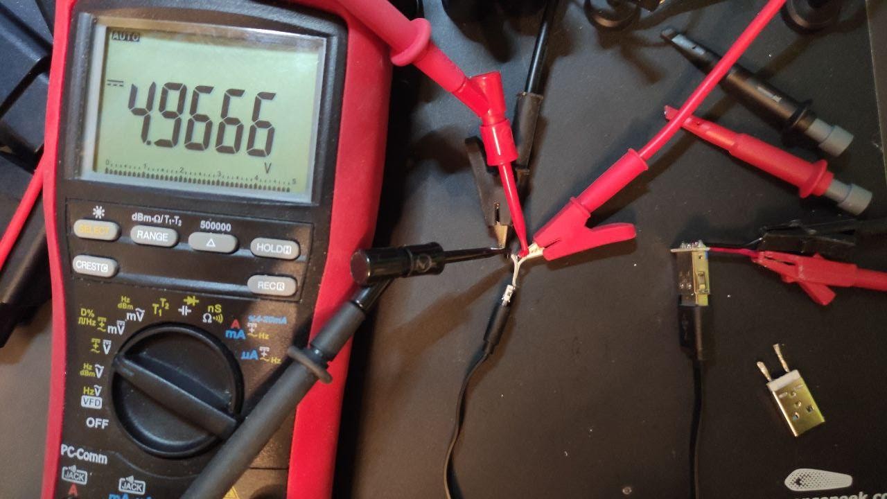
To test the cables, I used my favorite power supply, the Envox BB3. The TENMA 72-13200 device was used as an electronic load, but this time I also connected a multimeter (Brymen BM869S) to the test point in order to get accurate measurement results. BB3 output is connected to USB-A-connector (female). The TENMA and the multimeter are connected to the Micro-USB connector (female), and the cable under test connects these connectors during testing.
I tested 4 cables:
- An ordinary short cable (25 cm), which, if I'm not confusing anything, came with some kind of power bank.
- An ordinary cable 90 cm long, which was equipped with some kind of board for software development and debugging.
- A regular 200cm cable that I bought years ago to supply power to the Raspberry Pi 1.
- Tronsmart cable 180 cm long (with power lines made of 20AWG wires). Anker has similar cables.
In this test, I could include one more cable - the one that comes with smartphones (especially those that support fast charging). I have such a cable (with a Micro-USB connector), but it was used elsewhere during testing, so I did not test it. True, if you check it, it should show good results, since now it is used to power one Raspberry Pi and a voltage drop warning is not displayed at the same time.
Micro-USB cable test results
▍ Ordinary cable 25 cm long
| Cable current | Input voltage | Output voltage |
| 0.1A | 5.0V | 4.962V |
| 0.5A | 5.0V | 4.821V |
| 1.0A | 5.0V | 4.638V |
| 2.0A | 5.0V | 4,272V |
| 3.0A | 5.0V | 3.903V |
▍Normal 90 cm cable
| Cable current | Input voltage | Output voltage |
| 0.1A | 5.0V | 4.936V |
| 0.5A | 5.0V | 4.672V |
| 1.0A | 5.0V | 4.341V |
| 2.0A | 5.0V | 3.672V |
| 3.0A | 5.0V | 2.978V |
▍ Ordinary cable 200 cm long
| Cable current | Input voltage | Output voltage |
| 0.1A | 5.0V | 4.892V |
| 0.5A | 5.0V | 4.454V |
| 1.0A | 5.0V | 3.908V |
| 2.0A | 5.0V | 2.809V |
| 3.0A | 5.0V | 1,665V |
▍ Tronsmart cable 180cm long (with 20AWG power lines)
| Cable current | Input voltage | Output voltage |
| 0.1A | 5.0V | 4.963V |
| 0.5A | 5.0V | 4.803V |
| 1.0A | 5.0V | 4.604V |
| 2.0A | 5.0V | 4.209V |
| 3.0A | 5.0V | 3.811V |
In this case, if you raise the input voltage to 5.2V (as is done in the official power supply for the Raspberry Pi), you can get 4.37V at 1.2A, and 4.61V at 1.5A. As a result, this cable is very well suited for supplying power to the Raspberry Pi 3/4 when a longer cable is needed.
Outcomes
It turned out that chargers for phones, even no-name ones, are quite stable over the entire range of the current strength they support (this conclusion, however, I made on the basis of testing only four chargers). But USB cables, when you consider the voltage drop they cause, have a huge impact on how power is transferred from its source to various devices. The first three cables are ordinary cheap cables that should not be used to power "power hungry" devices. The cables that come with smartphones are usually good enough, so they can be used to power the same Raspberry Pi. Something else makes sense to use if longer cables are needed, or if cables of higher quality are available.
Finding a good Micro-USB cable is tricky, as most manufacturers do not specify the thickness of the power lines used in the cable specifications. If you choose a cable and can be guided by the thickness of the wires used in it, take the one that uses wires with a thickness of at least AWG20 or more (then the number in the AWGxx type marking will be smaller).
As a result, given that the Raspberry Pi (without peripherals) at full load consumes up to 1A (3 / 3B / 3B +) or up to 1.5A (Raspberry Pi 4), in the appearance of a lightning bolt icon (or in the issuance of a dmesg notification about voltage drop) is likely to be caused not by the power supply, but by the cable.
Have you had any problems finding power supplies and cables for your Raspberry Pi?