- Separate design
- Equal columns of keys
- Customizable column offsets
- Adjustable vertical offset for each finger
- 6-key thumb cluster

Split Squeezebox Keyboard
Left Side of Squeezebox 21a Keyboard Top View
Stationary position

Resting hands on the middle and bottom rows
I think the main design element that distinguishes my keyboard from similar ones is the shape of the middle and bottom rows. They are at a sharp 100 degree angle, and the starting position of the toe supports are the toes on the middle row and the pads on the bottom row. You can print on the middle row while maintaining contact with the bottom row, and vice versa. That is, your fingers do not need to reach anywhere in order to press two keys.

Press the middle row
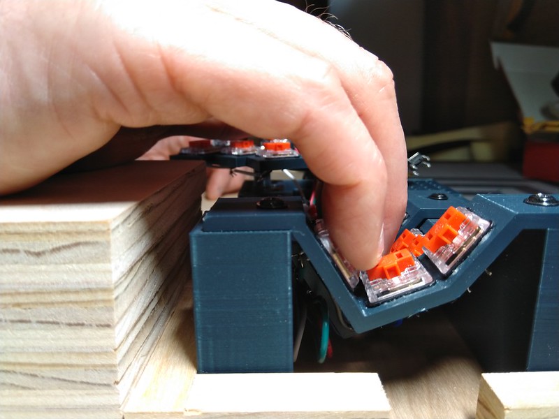
Pressing the Bottom Row
Also, since the switches are at such a sharp angle, you can press both with one finger while pressing in the corner. Both keys are pressed and released in perfect unison. That is, after adding a QMK combo to the layout, each finger has three symbols that can be driven without reaching anywhere.

One-finger chord on the middle and bottom rows
There is also an upper row, which is located and tilted so that you need to reach it minimally, that is, you get 4 keys per finger. The top row is so close that if you reach for it, you will miss. You don't need to reach out to him. You just have to "think" and you will be in.

Press the top row
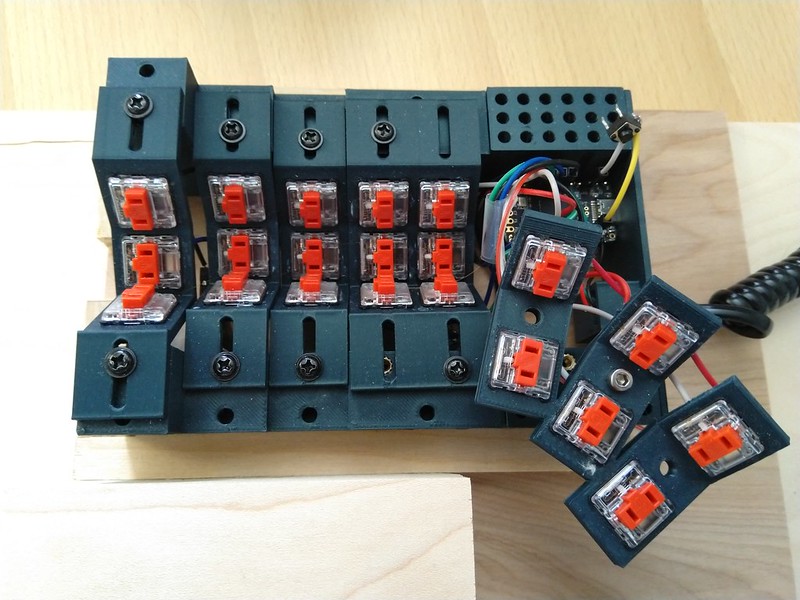
Physical location of switches
Main Grid for 4 Fingers and Cluster for Thumb
So we have a 3x5 grid for 4 fingers and 6 keys for thumbs, so there are 21 keys for each hand, for a total of 42 (cool!). The thumb cluster contains pairs of chaise longue keys, one flat and the other angled, making them easy to press individually or in chord. One column in the middle is the starting position for the thumb, the second must be pressed by moving the thumb inward, and the third by moving it outward.
Ergonomics and customization
The row spacing is designed to be as close as possible to the dimensions of the Kailh Choc switches. I knew from the beginning that I needed an even tighter arrangement, and if smaller switches were sold, I would have made it even more compact, but my system is already close to ideal.
The height of each column is changed in the parametrized CAD for the front / rear walls, for adjustment it is enough to enter the parameters and print the new wall. Basically, each column has its own height of the shelf that supports it.
To adjust the range, the column of each finger is positioned in the slots that allow it to be moved approximately 15 mm. It is enough to loosen the bolts a little, adjust the positions for each pin, and then tighten the bolts.

Thumb cluster support for adjusting the height and X / Y position
The thumb cluster can be raised / lowered by printing a different length of the thumb cylinder. You can move it left-right and closer-further along the grid of holes for threaded bushings. So far I've only tried two positions, so I only inserted the threaded sleeves into two holes, but in theory the threaded sleeve could be inserted into any round hole under the thumb cluster.
The cluster can also rotate around the axis of the bolt that secures it to the keyboard case.
My initial goal was to turn a keyboard into a device that can be customized for most people. Probably, this can be realized by changing the heights of the columns using stands resembling LEGO parts. But at this stage, to adjust the heights of the columns, you need to specially print the details. Everything else can be adjusted mechanically, at least within the limits of the length of the wires.
Bare switches
No caps! Choc switches have ideal stem stems. The compact geometry that I wanted requires an extremely small gap between the middle and bottom row switches, and the caps will get in the way. When viewed from the side, you will notice that the lower row derailleur finger rest hangs slightly over the middle row derailleur support. Strictly speaking, the keycaps could be used on the top row and thumb clusters, but they practically don't make any sense, and I think the keyboard looks hipster-cool without them. It's like a fixed-gear bike from the world of keyboards. The switches are rotated 90 degrees from the standard position to reduce the column pressure gap for each individual finger.
Connection and soldering
I liked some of my first prototypes immensely. For example, this one, which was a vertical block, it was adjusted in two directions with several slots.

This prototype seemed great, but soldering inside all of these cases would be a real nightmare.
But then I realized that there was no way you could get in there with a soldering iron to connect them all. I had to drop several versions before settling on something that could be soldered.
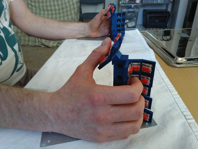
The current removable wall design also simplifies manual wiring. I did three soldering steps with each switch when it was completely removed from the case, and then glued them in place. It helped a lot in the build. With this scheme of work, the connection of the wires can be done with only one fixed wall, so on the other side there is a lot of space for the soldering iron and moving the wires manually.

Soldering before assembly

Connecting finger columns while only one wall is attached
Keys under wrist rest
For the most comfortable pressing geometry, the bottom row of the Squeezebox requires a high wrist rest to allow your fingers to hang over the edge and touch the keys.
Knee stand
While tinkering with the jumble of two separate keyboards on my desk, I accidentally put the Squeezebox on my lap and realized that I could align the armrests of my chair with the wrist rests and get a very comfortable position. The forearms rest on the armrests of the chair, and the wrist rests are directly in front of them at the same height. The stand can also be a mouse surface in the middle. Therefore, for now, I plan to use the keyboard lying on my lap as my main pose. But it is quite convenient to work with it even when it is lying on the table.
Knee stand and chair armrests
3D printing
This version consists of six separate parts. I connect them by drilling holes in the threaded bushing insertion surfaces and fastening the parts with M3 bolts. I have never used threaded bushings in 3D printing before; turned out to be great, they are very easy to model and mount with a soldering iron. I love them and will use them in future projects.
After slicing, no parts need to be supported. I printed a small washer for the bolt holding the Elite-C microcontroller to prevent the head of the bolt from shorting out the PCB.
The growth of my modeling skills is very noticeable as I work on the project. Modeling the first parts and prototypes required many hours of work in FreeCAD, I started over many times and created many versions of the files in git. But at the end of the project, I modeled the inner wall with space for the RJ-9 connector, the microcontroller and the USB-C port in less than an hour, and I successfully printed everything on the second try.
At the very beginning, I did not understand a simple thing that turned out to be very convenient: for a symmetrical split keyboard, almost all the differences between the right and left sides can be conveyed by performing a mirror image in a slicer program. This means that you only need to model one half in CAD.
Learning curve
In general, the training is not very different from my usual ergodox, especially since I gradually reduced the number of keys of my ergodox over the years, learning new QMK features and layout techniques. However, the change is drastic enough to bring my typing speed down from 60 wpm to 20 wpm. I haven't typed very much yet, because I am still improving the keyboard layout in the area of punctuation and other aspects. I am confident that after a week or two of practice in the evenings, I will have gained enough speed and accuracy to switch to everyday use.
Details of keyboard parts
I used Kaihl Choc Red switches - linear, low profile, quiet switches with low actuation force. I used Elite-C as microcontrollers. The keyboard parts are connected by RJ-9 cable and software serial configuration. Threaded sleeves are designed for M3 bolts. All in all, this is a fairly standard approach to making a homemade keyboard by hand wiring.
Key layouts
My arm was in pain due to chronic tendon sprains when the little finger reached out to the outer column and pressed a chord with Shift on my ergodox, so I had a strong motivation to reduce the load on the little finger and transfer the load to the thumb, because of this in my there are no columns out of the little fingers on the keyboard. Shift and Control / Escape moved under the thumb (and / or in a QMK combo, but I'm still working on them), and Tab moved to the navigation layer, so the little finger was left with only pressing the letter keys. I will probably someday switch to a circuit that minimizes stress on the little fingers, for example, BEAKL, but I did not want to get used to it in parallel with mastering a new keyboard.
I left one inner column to drag to because I wanted to keep the base layer for Dvorak so I didn't jump straight to something new. That is, the inner column is really only needed to facilitate my transition to the new keyboard, but eventually I will probably create a layout that doesn't require it and get rid of it. To reduce the distance the finger needs to move sideways, the two inner columns are located on the same plate, so the gap is quite small - only 2 mm.
The process of exploring the possibilities, including modifiers, is not over yet. I tested the main row modifiers, but with Dvorak they are very prone to false positives on the right hand with combinations like th and ns, so I moved them to the bottom layer of my ergodox. But if you put modifiers in the bottom row on the Squeezebox, then you can't create combos with them, which is why I lose a lot of the potential of this design. I guess next time I'll try modifiers just for Ctrl and Alt on the top row so that I can hit single-finger combos in the middle and bottom rows. Having so many keys for the thumbs creates many great possibilities, especially for actions that are only needed occasionally.
If you are curious about the details, then in my the QMK fork has my layout.
Video
Conclusions on creating a working homemade keyboard
It was a very exciting project. I've wanted to implement it ever since I first described the concept of angled keys to my keyboard colleague Michael Sloane in January 2020. My experience with CAD and 3D printing was very low and I had never created parameterized CAD before, only worked a little with TinkerCAD and SketchUp. Parametrization is absolutely essential for projects like this, so I did a little research on the dactyl manuform software stack (clojure, openscad), but ended up simulating everything in FreeCAD with good results.
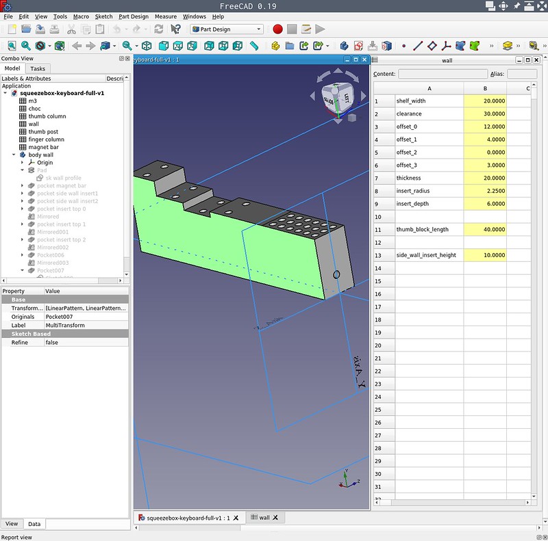
FreeCAD project showing spreadsheet parameters and main wall model
This project took at least two months of significant work in the evenings and weekends, as well as the development of a large number of prototypes (more on this below). I have soldered several keyboard kits before, but have never manually connected wires or configured the QMK firmware myself. I suffered a lot with microcontroller firmware and how to tie wire connections to firmware. I am grateful to the many people from the forums on Discord and Slack who answered my questions and helped me with issues every week.
Plans for the new version
What I dislike about this version is that the angle between the top and middle rows of the ring and middle fingers is too sharp. I can't really type in the top row with my fingertips as intended. Instead, the nails scratch the cap. This is because I originally designed a joystick-style vertical orientation in which this angle is fine. But in the process of work, I switched to horizontal orientation, and did not understand that this would affect the geometry. This angle is ideal for the index finger and pinky finger, which is a bit strange, but in the next version the top row for the ring and middle fingers will still be almost flat, about 170 degrees.
I added grooves for the magnets so that the keyboard and wrist rests can be mounted on a steel plate glued to a 1/2 "piece of plywood for the knee stand. Perhaps I can replace the coiled RJ-9 cable with a flat one so it can be attached to the plywood and run it along the edge, thus completely freeing the center of the mouse stand (or for coffee when the keyboard is on the table).
In this design, I did not take into account the need for space for the physical reset button, because I thought that I would make the reset key in the layout. It turned out to be a very optimistic decision, so I had to stick it on and it hangs from the wires. In the next version, I will come up with a suitable place for it. I expected the QMK setup and flashing to be a fairly quick process and I only need a few flashing. How wrong I was. I spent a whole few days off debugging strange behavior: at first, 39 out of 42 keys worked, and then suddenly none of them worked, then by accident only the bottom row started working, then everything started working, but the keys were in the opposite order, and so on.
I will add a simple outer wall that will attach to the main walls via threaded bushings. This will ensure that the entire structure is aligned.
I am also considering completely redesigning the cluster for the thumbs. Probably, I will place the keys of the top row next to each other.
I have a spool of black PLA Prusament that will look great with Choc Red switches.
Long weeks of prototyping

One of the first vertical prototypes with two levels of adjustment using slots and slots.
Initially, I thought it would be a vertical design, used like a joystick, similar to Viktor Aikman's Concertina . After a lot of prototyping, I decided to drop this complexity-added requirement and opt for a standard horizontal tilt layout.
I chose the name "Squeezebox" because the hand position and the tightness of the keys made it look like an accordion or concertina. Squeezebox is the slang for these tools. Even after I decided to design the horizontal design, the name was retained because the cases were box-like and the corner keys were squeezed, so it felt right.
Also, I am very interested in vertical orientation combined with the squeeze of switches, because I used to play saxophone and I would like to feel similar movements when typing.
Vertical prototype, adjustable by rows of slots and bolts.
The layout for the main columns of four fingers I implemented very quickly. At that time I was just starting to learn parametric 3D modeling in FreeCAD, so I had some difficulties with the implementation of my ideas in the program. To create a two-dimensional adjustment (front-to-back, higher-lower), many prototypes had to be built and almost two full spools of PLA filament had to be spent. I've had slotted structures, bolted structures, magnetic fasteners, adhesive fastened structures, held together like LEGO pieces, etc. Some of these prototypes were difficult to wire together, so after getting the right positions the hardest part was connecting the wires manually.
Two joystick prototypes with magnetic bases
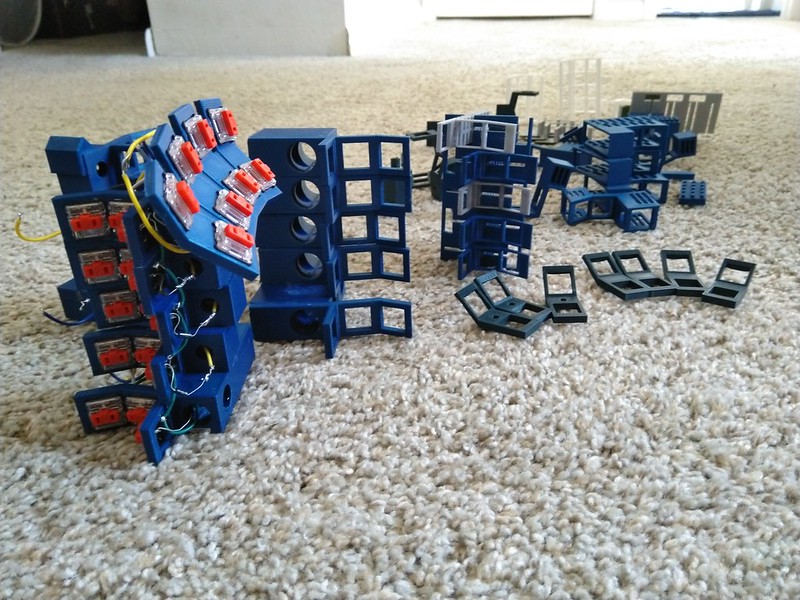
Prototype garden
Entire album with assembly photos
The album contains over 150 photos and can be viewed on Flickr .