In this short article I will try to explain the basics of electrical engineering on my fingers. For those who do not understand where the electricity comes from, but it seems to be indecent to ask.
1. What is electric current.
"The chief engineer turned the switch, and the electric current ran faster and faster through the wires" (c)
1.1 A couple of general words on the physics of the question
Electric current is the movement of charged particles. Of the charged particles, we have electrons and a little bit of ions. Ions are atoms that have lost or acquired one or more electrons and therefore have lost electrical neutrality, acquired an electrical charge. This is how the atom is electrically neutral - the charge of the positively charged nucleus is compensated by the charge of the electron shell. Ions are usually charge carriers in electrolytes, and electrons are carriers in metal wires. Metals conduct current well because some electrons can jump from one atom to another. In non-conductive materials, electrons are attached to their atom and cannot move. (Let me remind you that this article is an explanation of physics on your fingers! Search in more detail under the "electronic theory of conduction").
We will consider the current in metal conductors, which is created by electrons. An analogy can be drawn between electrons in a conductor and a liquid in a water pipe. (At the initial stage, electricity was considered a special liquid.) Just as water does not pour out through the walls of a pipe, so electrons cannot leave the conductor, because the positively charged nuclei of atoms will attract them back. Electrons can only move in the inside of a conductor.
1.2 Generation of electric current.
But just like that, the current in the conductor will not arise. It's like pouring water into a piece of pipe and weld it at both ends. The water won't flow anywhere. In a piece of conductor, electrons also cannot move in one direction. If the electrons for some reason move to the right, then an uncompensated positive charge will appear on the left, which will pull them back. Therefore, electrons can only jump from one atom to another and back. But if the pipe is rolled into a ring, then the water can already flow along the pipe, if somehow it is made to move. Likewise, the ends of a conductor can be connected to each other, and then the electrons can move along the conductor if forced. If the ends of the conductor are connected to each other, then a closed circuit is obtained. Direct current can only flow in a closed circuit. If the circuit is open, no current flows.A pump is used to force the water to flow through the pipe. In the electrical circuit, the battery will play the role of the pump. A battery drives electrons along a conductor and thus creates an electric current. Scientifically, a battery is called a generator. So in electrical engineering they call a pump to create an electric current.
- .
, ! .


, - . - , - . , - . , .

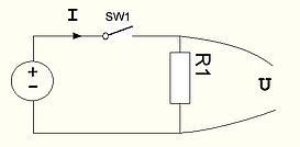
, - , , SW1 - , \ , R1 - \ - . - , . - , . . , . . () , ! 0, . U! , . ( ) .
.

? ! I, , ( ). - I. () .
- I! () . .
- . ( " . " ())
2. .
c
R U,
I =U/R
R I, U=I*R
- . , . R=U/I. - - U, I, R. , . . -

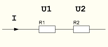
R1 R2 I. U1 U2?
!
, . , I. .
- " ", "" () , , U=I*R.
.
1. .
, - - .
( " . " ())
3.
.

, .
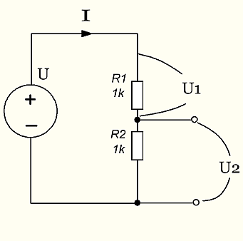
, (), . () . - R. . 1 , .
. ? , R12. I, R1 R2. R1 U1=I*R1, R2 U2=I*R2. . U=U1+U2, . U=I*R1+I*R2=I*(R1+R2).
.
I=U/(R1+R2)
, U2. U2=I*R2= U* R2/(R1+R2).

. , Ux .
- () (, )

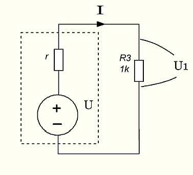
, ∝. . , . r.
, , , . 10, , . 1 , . 0.5, . , - .
If the output resistance of the source (internal resistance r in the figure) is comparable to the input resistance of the receiver (R3 in the figure), then these resistors will act as a voltage divider. In this case, the receiver will not receive the full voltage of the source U, but U1 = U * R3 / (r + R3). If this circuit is designed to measure the voltage U, then it will lie!
In the next articles, it is planned to consider circuits with capacitors and inductors.
Then diodes, transistors and operational amplifiers.