In April 2020, I purchased a pair of EdgeStar AP14001HS outdoor air conditioners because I thought I would spend most of my summer indoors. At home, I cannot install window air conditioners, although they would be an obvious choice in terms of efficiency, because all the heating parts remain outside.
Similar Models
Judging by the photos from the Internet, the following air conditioners have a similar design:
- EdgeStar AP14001HS
- Whynter ARC-14S
- Whynter ARC-14SH
- Whynter ARC-141BG
- Whynter ARC-143MX
I can't say how similar they are, but the content of this article may apply to them as well.
Air gaps
I wanted to buy a dual duct air conditioner because single duct models are thermodynamically suboptimal. Blowing hot air from the window creates negative pressure in the room, due to which air from the outside is sucked back through various cracks. In theory, dual duct models eliminate this problem by cooling the condenser with outside air, which is then vented again.
However, when checking the inlet and outlet ducts of the AP14001HS, it turned out that the volume of air passing through the inlet duct is much less, that is, the air must enter the condenser chamber from the room, and also move between the room and the street while the fan is off. There are two main places where this happens:
1. At the junction of the lower part of the case with the front:
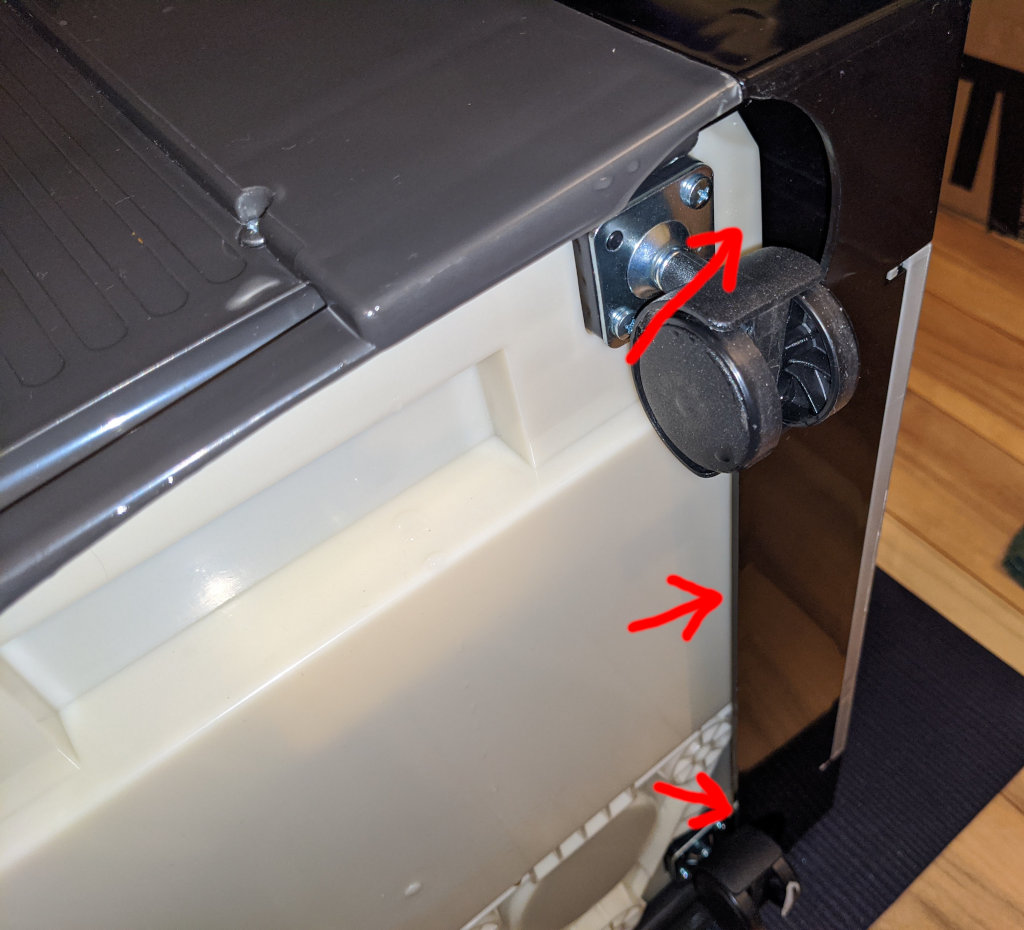
I covered it with masking tape:
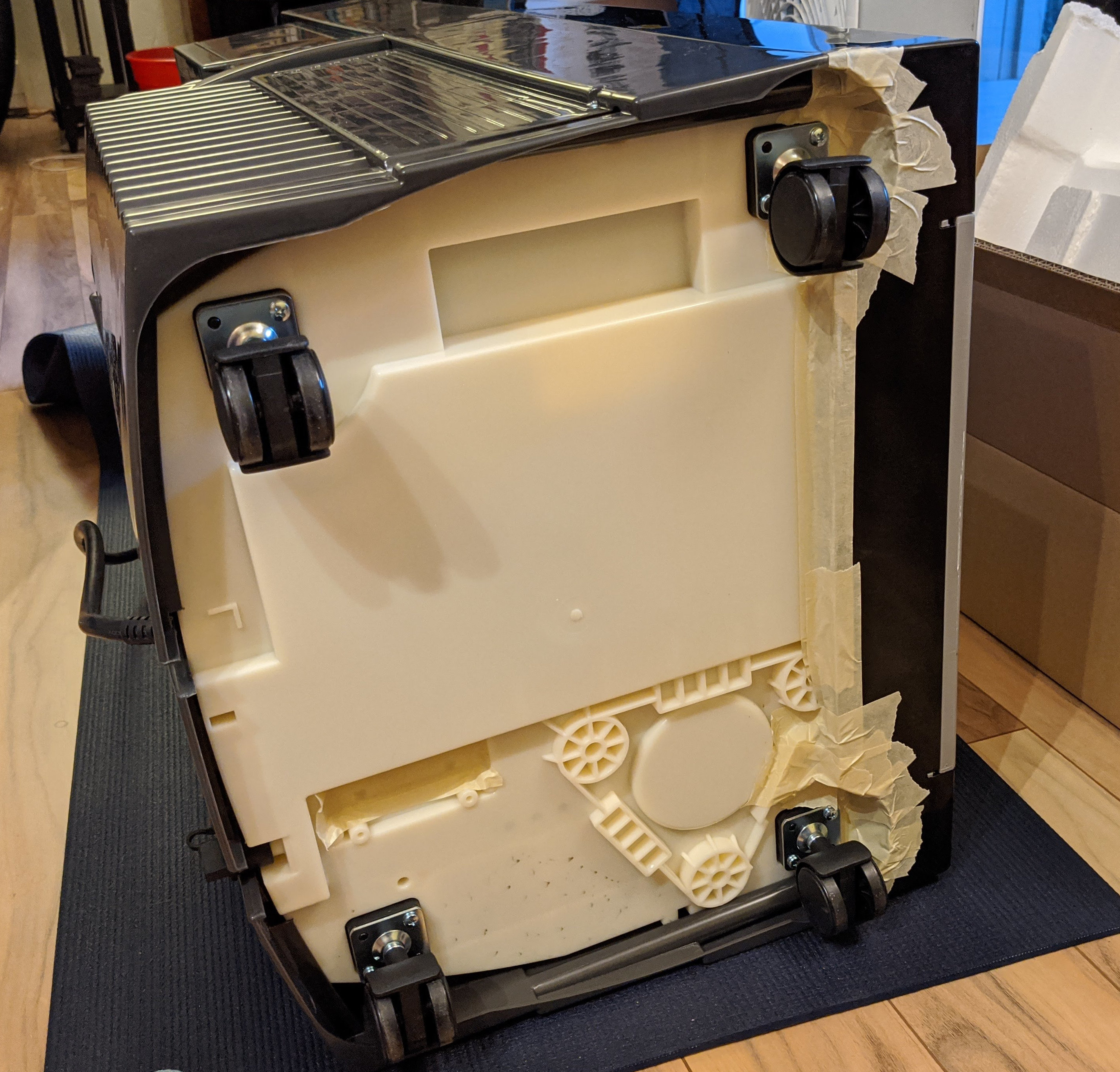
2. Behind, under the air filter:

To cover this hole, I cut a 436mm x 98mm rectangle out of 1/16 "(1.5mm) ABS sheet . A cardboard oatmeal box would work as a prototype. In general, the material should be quite thin, but at the same time quite hard to keep a flat shape.
when the compressor plastic is pulled to the rear, and otherwise - to the front, so hold it in place will allow a piece of adhesive tape or masking tape.
Finally, if you decide to open the device (this is useful 12 '' Phillips screwdriver for M3.5-M5), it will be possible to tape the internal duct / wire gaps, but I don't know how important they are.
Will it not burn?
These modifications are designed to raise the temperature of the condenser compartment, which can reduce the life of some components, but I have no idea which ones and how much. At least I have a couple of proofs that this is not such a bad idea:
1. I asked EdgeStar tech support about sealing the bottom gap:
[]
EdgeStar AP14001HS , , . , . . , . , - ? , , .
[ EdgeStar]
, ,
EdgeStar.
.
, . , .
[]
. , , , , .
AP14001HS :
- (ASHRAE) 14000 BTU (4,1 *)
- (SACC) 8600 BTU (2,5 *) ( 38% )
, « » SACC:
https://support.edgestar.com/hc/en-us/articles/115005480926-What-is-SACC-Seasonally-Adjusted-Cooling-Capacity
( ) ?
[ EdgeStar]
, ,
.
. , SACC . . .
, , , . SACC, .
2. A user on the grower forum reported that the Whynter ARC-143MX is capable of being sealed enough to maintain a high CO2 atmosphere. It is not clear from the text how long it worked, but the topic was opened 4 years ago, and its author did not write anything about equipment failures.
Therefore, it cannot be said that there is no danger of damage to the device, but at least someone has already tried this.
After insulating these gaps, I felt that more air flows through the inlet duct, and when it is briefly blocked, less air begins to flow from the outlet.
Move away, I'll do science
To test these modifications, I installed the air conditioner in a fairly insulated 1.5 m² closet. Initially the temperature was about 72 ° F (22 ° C), setting the air conditioner to 61 ° F (16 ° C) (minimum), I turned it on and waited about 3 minutes until the fan turned off.
The experiment was repeated three times in the factory configuration (red lines), three times with closed gaps (blue lines), and finally two times in “single duct mode” (black lines) in which suction was performed directly from the cabinet space. I recorded the temperature with a phone pointing at the thermometer, on which the Open Camera application was started to take photos with a repeat every 10 seconds:
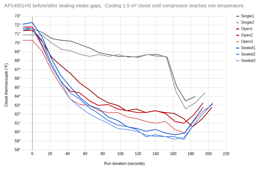
I don’t think such a circuit is reliable enough to calculate absolute efficiency, but it’s obvious that the closed-gap configuration is better for cooling, and the single duct mode is just awful.
Nagging
I find it shameful that the manufacturers of floor-standing air conditioners are so careless about efficiency, which can be improved with the help of simple household goods. It reminds me of the computer power supply industry before the introduction of the 80 Plus, when everything sucked and no one knew what to buy. Why is all innovation focused on single duct air conditioner designs?
Places like the San Francisco Bay Area are full of apartments and rooms that gradually become unusable as temperatures rise, so it would be great if people could just buy a decent product.
Probably knows his stuff http://www.climax-air.com/because this company produces (at least in 2020) the only floor-standing air conditioner with dual duct and variable speed compressor. But I only found this out on the website because their products are very scarce. Perhaps I'll pay attention to them again when EdgeStar crashes.
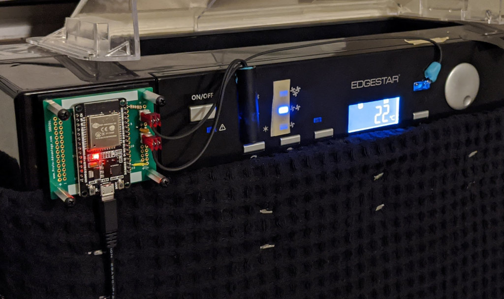
Pictures of installation in the cabinet
(The second AP14001HS, seen in the mirror, was used to set the room temperature.)


Room information
Each device consumes about 10.5 A, so it is important to determine which circuit breakers are connected to which outlets so as not to connect the device to a circuit with other devices with high current consumption, such as a microwave oven or electric kettle. Ideally, they should also be at opposite ends from the main machine. So far, I have had no problems connecting the device to a 15 A circuit along with a refrigerator or computer.
On a day when the maximum temperature reaches 95 ° F (35 ° C), two always-on air conditioners can maintain an 850 sq. feet (78 square meters) approximately 75 ° F (24 ° C). Based on my infrared thermometer, the ceiling is much warmer than the walls, so it might be worth improving the insulation of the attic.
I plan to turn them on in winter for heating, while they will use less energy than resistive baseboard heaters, but time will tell how much this is true.
The flaw with this scheme is that my windows are blocked / taped, so I cannot open them in the evenings when the outside air is cooler. It would be nice to have an automatic ventilation mode for this case. However, the air conditioner cooled by cool air blows out even cooler air, so it does not need to work in this state for long.
Simpler hacks
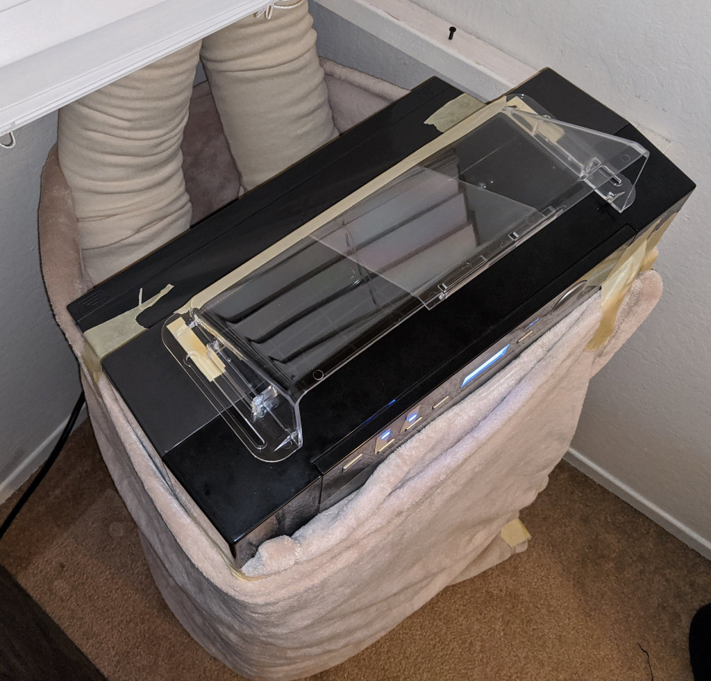
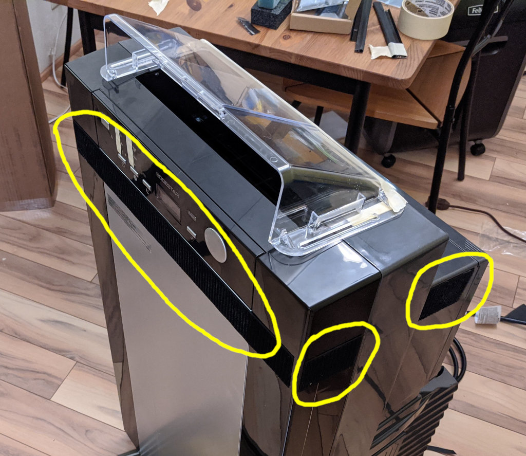
This appliance blows indoor air mainly upward. I opened the case and removed the built-in reflector, replacing it with a Frost King HD9. It creates an approximately horizontal air flow, and the device seems a little quieter due to the absence of these extra plates.
(Note in the photo: I taped on the LEDs to reduce their brightness, and a piece of foam was left from an abandoned experiment on soundproofing using semi-permanent glue.)

These ducts can be insulated with a 6 "cotton tube sleeve. After 5 minutes of running with two layers of cotton fabric, I got 122 ° F (50 ° C) on the duct and 102 ° F (38 ° C) on the surface of the fabric. It is not the best insulation material, but it is cheap, easy to use, and quite suitable.

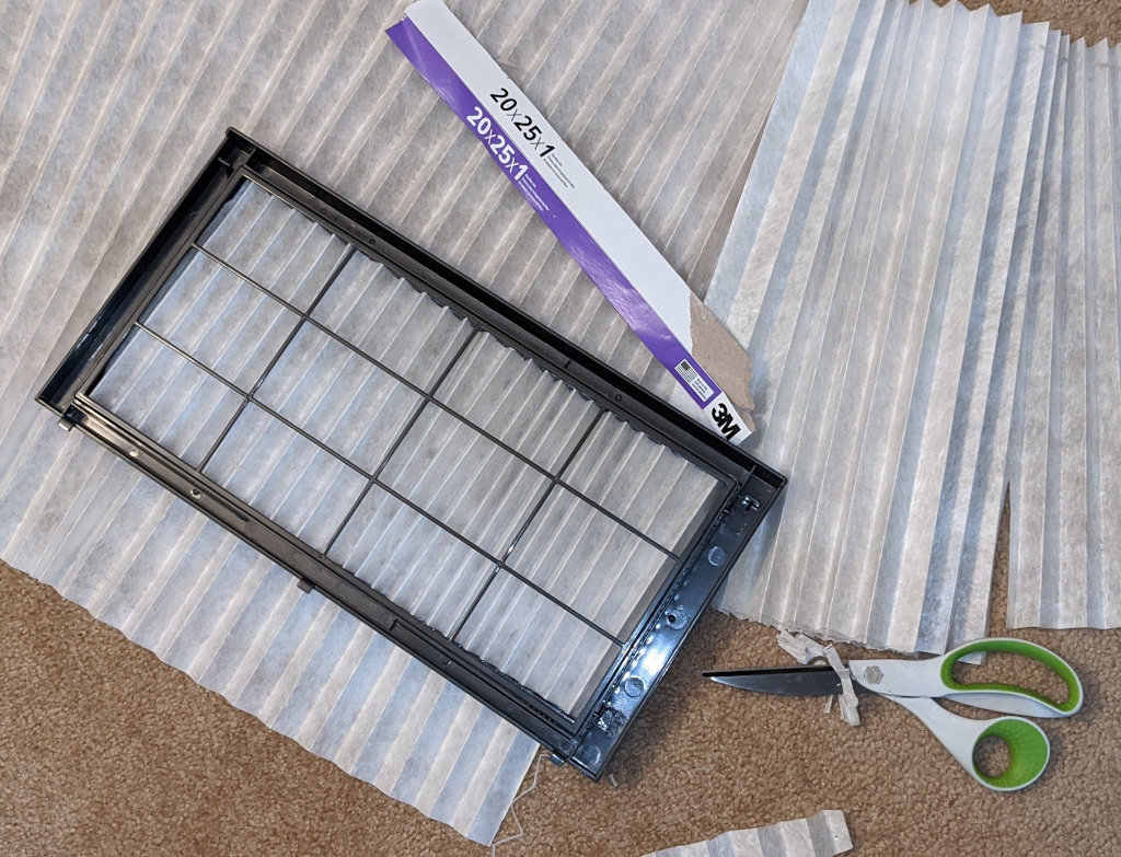
You can open the standard heater air filter and cut a zig-zag part to fit the plastic frame of the intake duct. It is worth noting that this will restrict airflow, so it would be logical to increase the fan speed. After taking this photo, I increased the density a little:
Soundproofing
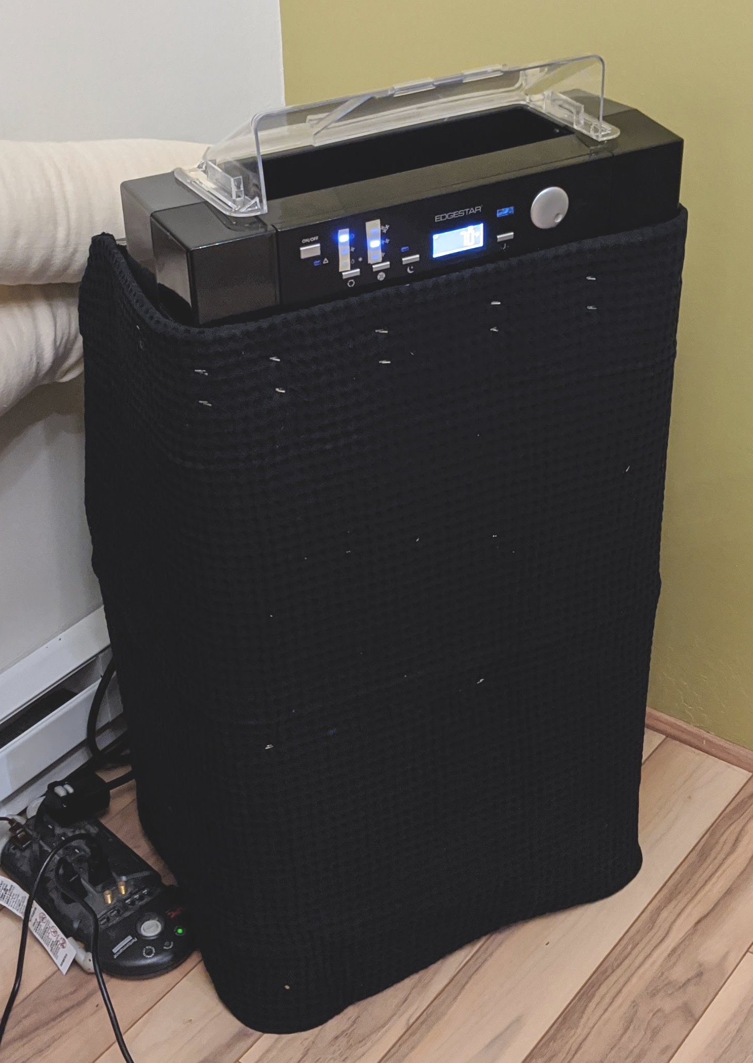
To keep the device quiet, I first wrapped it in a duvet, secured with duct tape. Air ducts do not allow anything to block the room air intake. Here's my prototype for a "conditioner burrito":
After operating the unit for several hours in a 90 ° F (32 ° C) outdoor temperature, the hottest part under the blanket was around 94 ° F (34 ° C), so it looks like the unit is doing quite well with its cooling.
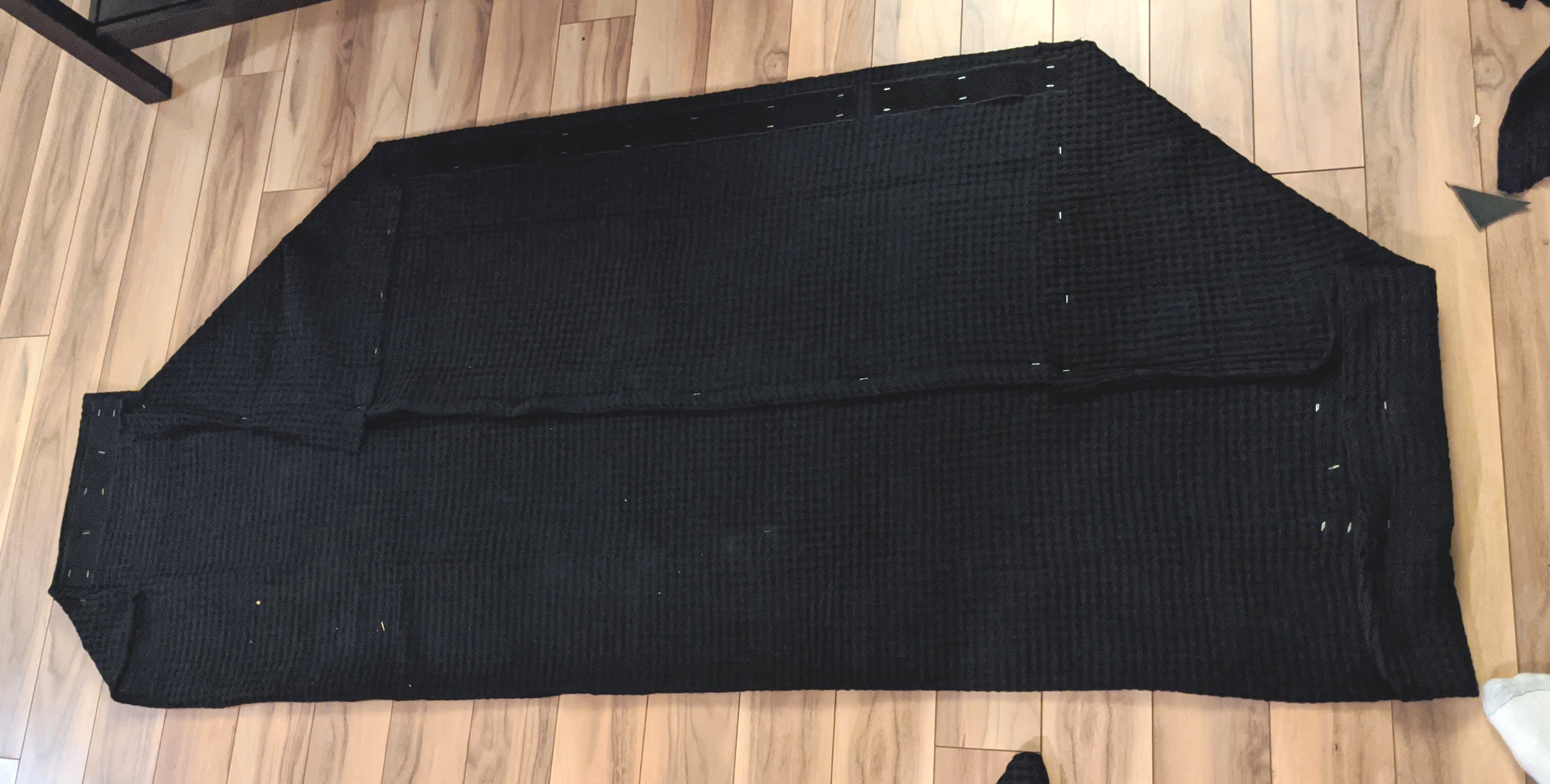
To create the enhanced version, I used mass loaded vinyl (MLV) wrapped in a cotton blanket with Velcro fastened with staple staples.
Here are the approximate material costs for two fixtures:
- Roll MLV 1 psi 4ft x 12.5ft: $ 110
- Two double cotton duvets (66 x 90 inches): $ 50
- Multiple yards of 2-inch Velcro: $ 10
- 9/16 '' staples (Bostitch BTHT73533): $ 4
I used the following sizes:
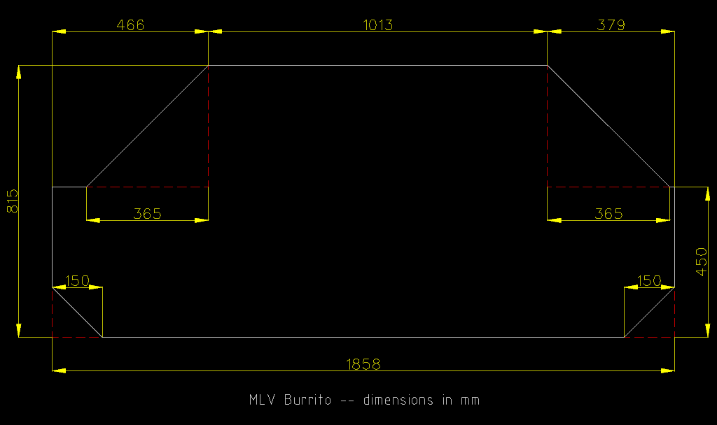
I cut the MLV to size using a tape measure, square, pencil and scissors. By cutting off the bottom corners, we leave room for the power cord. The sides are different lengths because the power cord is off-center.
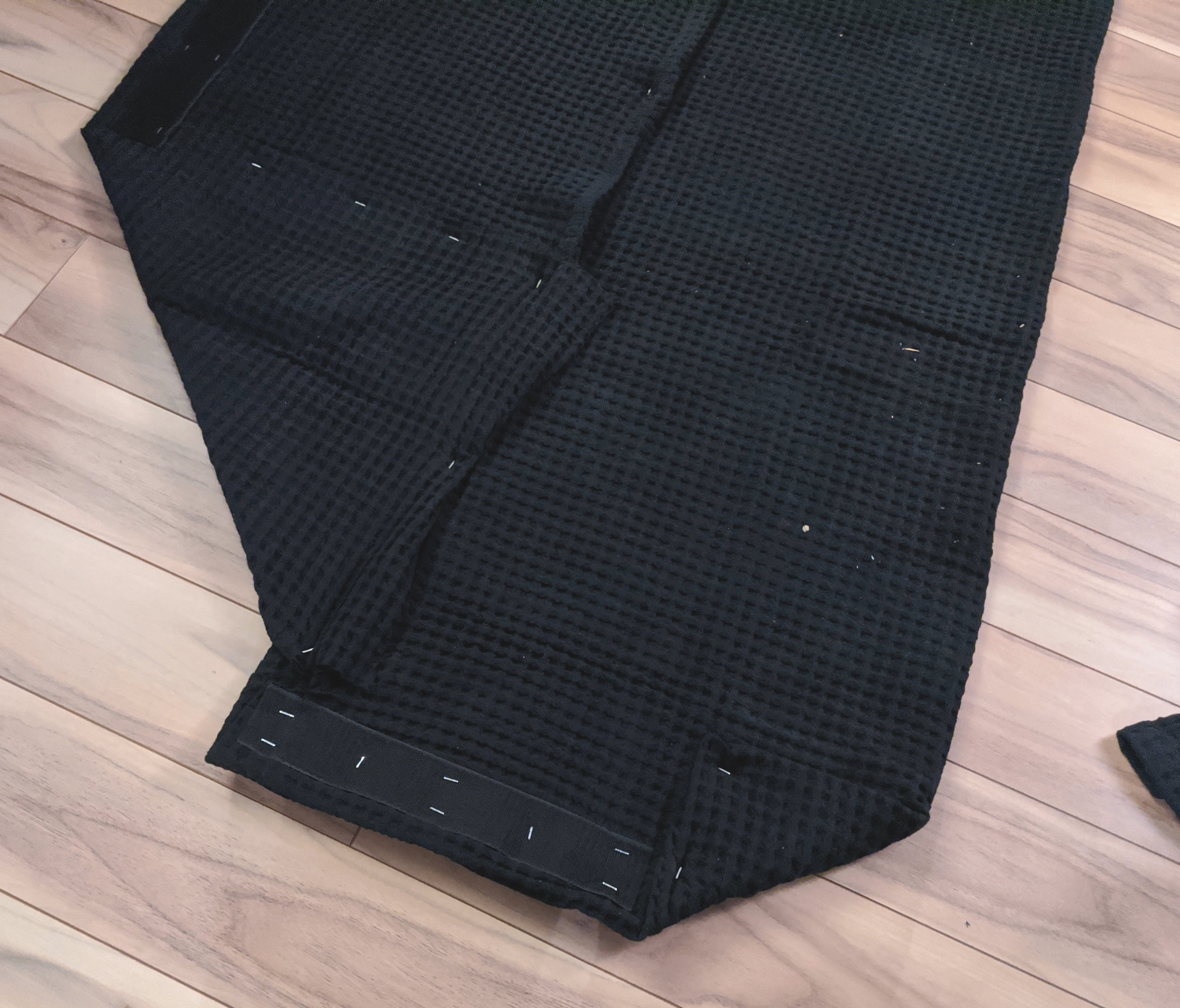
Velcro fasteners are fixed at the top and side (the corresponding fasteners are glued to the air conditioner with a glue gun) so that the "burrito" can be held together by its edges.
Photos of Burritos from MLV:
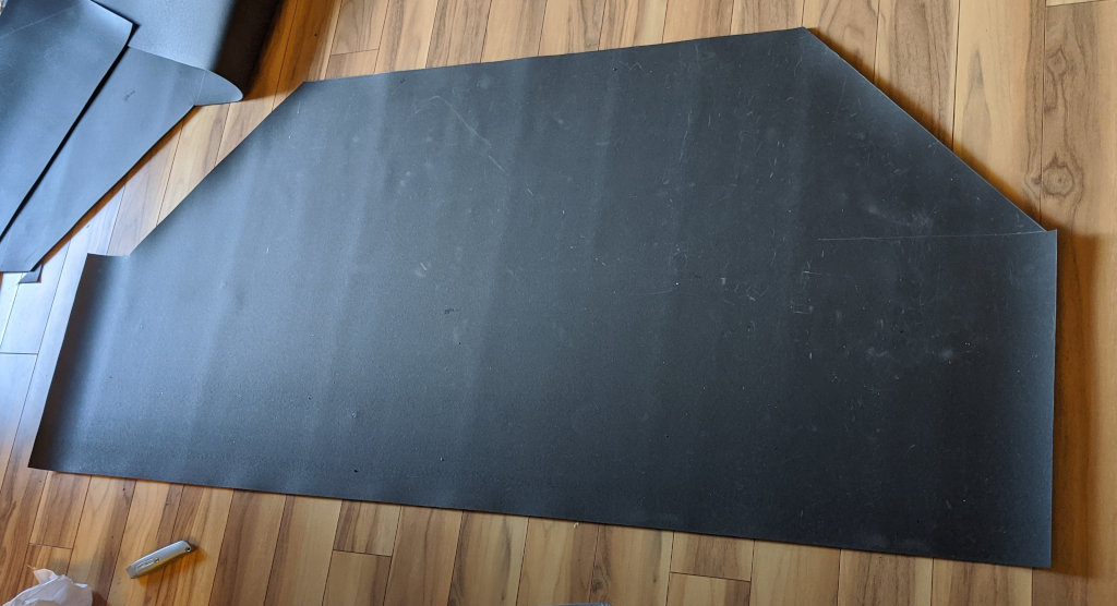

Ultimately, MLV did reduce the compressor noise, but the fan noise is still quite loud. I don’t know how much the cotton "wrap" helps to reduce reflected sound, but at least it looks prettier this way than with bare vinyl.
I spent quite a lot of time attaching and bending hundreds of staples. I think it’s worth recommending to a sane person to stick with my initial solution with folded blanket and duct tape, because it only takes a few minutes and MLV is not that much better.
Network control
I have connected an ESP32 microcontroller to the “stage 1 compressor relay” (Y1) and “heat pump changeover valve” (O) pins of the Nest thermostat, whose “auxiliary heat” output controls the baseboard heater relay. (I have verified that the Nest can turn it on individually, but time will tell if it can handle two heating methods in winter.)
Each 24VAC relay output feeds the input pins of the SFH620AGB optocoupler through a 10K resistor (24V / 10K ohms will be fed to the LEDs optocouplers several mA). The optocoupler is compatible with GPIO in mode
INPUT_PULLUP
and uses software to clear the signal. I borrowed this idea from a post on StackExchange , although 24VAC is less intimidating than 120-240VAC.
On the air conditioner side, I control a standard infrared LED through a 150 ohm resistor using a function
sendRaw()
from IRremoteESP8266 .
I cut the ballpoint pen in half, painted it black and fixed it over the mode indication LEDs, and the INL-3APD80 photodiode will detect the brightness changes when the modes are cycled. It looks like the photodiode works better in photovoltaic mode with the anode connected to the ADC input and the cathode connected to GND. I take a read every 50μs and average the values over 1000ms (20,000 samples) to get a clean signal. By adding a capacitor in parallel with the photodiode, the stabilization time is reduced; 10 nF seems to be a good balance between noise and response time, bringing the read time down to 100-200ms.
The rationale for connecting an outdoor air conditioner to the Nest is as follows:
- The usual smart features that Nest provides
- -
- / , , 60-70
I am intercepting the console codes using the
mode2
LIRC package that transmits the mark / space time in microseconds, which is compatible with the function mentioned above
sendRaw()
.
Reverse engineering of the IR protocol has been carried out: all marks have the same length, and the data is encoded in spaces. They appear to be 32 bits per packet, lined up as
[id, ~id, code, ~code]
. I tried all 256 codes, trying to find undocumented functions like "set power to X" or "set mode to X", but alas, they were all duplicates of the standard 6 buttons, so knowing the protocol is almost unnecessary.
Here are simplified JSON IR codes
irrp.py
(I originally experimented with
pigpio
on a Raspberry Pi.)
This algorithm allows the ESP32 to detect the condition of the air conditioner at blind start:
- Sampling the brightness of the photodiode
- Sending POWER
- If the brightness has increased, it means that we have turned on something, so we transmit POWER again
- We now know that the device is turned off
- We send 4 times MODE, reading the brightness after each transmission
- We mark the brightest mode as COOL (because this LED is closest to the photodiode)
- We mark all other modes in their order relative to COOL
It is possible to synchronize the fan speed by running DEHUMIDIFY for a short time (this mode causes the fan to switch to LOW mode), but I decided not to do this and just let the user select the fan speed.
I encountered the following bugs specific to AP14001HS:
- It is not possible to switch modes reliably while the power is on, because, for example, when switching in the COOL-> DEHUMIDIFY-> FAN order, sometimes the middle mode (DEHUMIDFY) is turned on, even if the IR signal is applied as quickly as possible. So I had to switch the compressor to idle by sending TEMP UP rather than switch to FAN.
- (OFF), MODE-MODE-POWER , , , . 1000 MODE POWER.
- «» , 0-2 . , , - F->C->F .
- , IR- ; .
- IR- 1200 , . , , «1».
A specific temperature can be set by sending DOWN commands to reach the minimum value followed by UP commands to increase to the desired temperature. In theory, the controller always uses 16C for cooling and 32C for idle, but I prefer 18C-27C because it only takes 9 clicks (shorter squeak) and the user can manually set the cooling point to keep the small room from getting too cold. Manual adjustment is only possible in Celsius mode due to a temperature conversion bug, so it is very inconvenient that the air conditioner returns to Fahrenheit when the power is turned off. The best I have come up with is to send enough UP commands to initialize the cooling mode to reach the maximum value in Fahrenheit,and for heating mode - the same with the DOWN commands. Any changes after this point will be counted in Celsius, so the temperature will never get low enough to cool down or high enough to heat up until the user switches to Celsius mode and reboots the ESP32. In other words, it's better to let him never works, than works somehow .
Photos of the controller
I couldn’t find a case with the correct dimensions, so I cut out some rectangles of ABS with a utility knife, fastened them with 5mm and 12mm M3 screws with 18mm uprights and 5mm spacers.

I used a Proto Advantage SBB206 PCB. It ideally fits an ESP32 board with 15 rows of pins, although it would be better if the board was one pin narrower. By drilling holes in the power rails, multipurpose components can be installed in them.
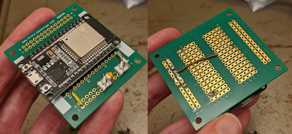
Photodiode and IR dongles are connected to 22AWG MTA-100 connectors. Instead of a $ 35 specialized tool, I used a small screwdriver.

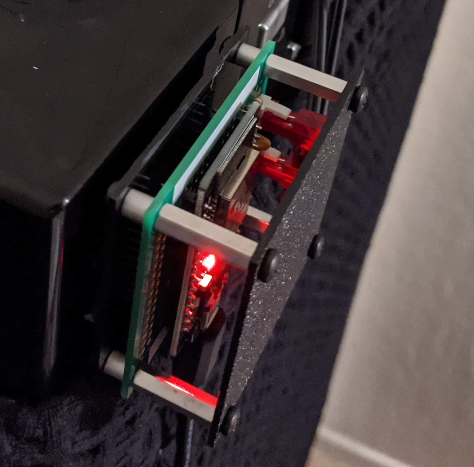
This is how the controller attaches to the AP14001HS:
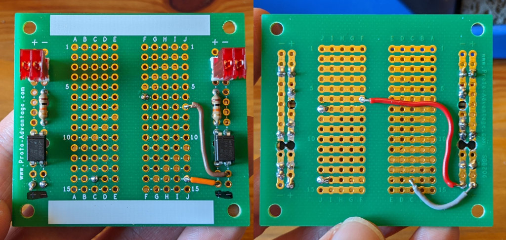
Pictures of thermostat / relay
Relay box 24VAC with 10K resistors and optocouplers:
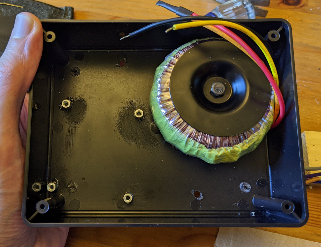
Bud Industries CU-387 housing with Vigortronix VTX-146-030-212. The transformer converts 120VAC (parallel windings) to about 30VAC or 208VAC (series windings) to about 25VAC. I roughened the plastic with sandpaper and epoxy 6mm M3 posts; hopefully it will hold on tightly enough.
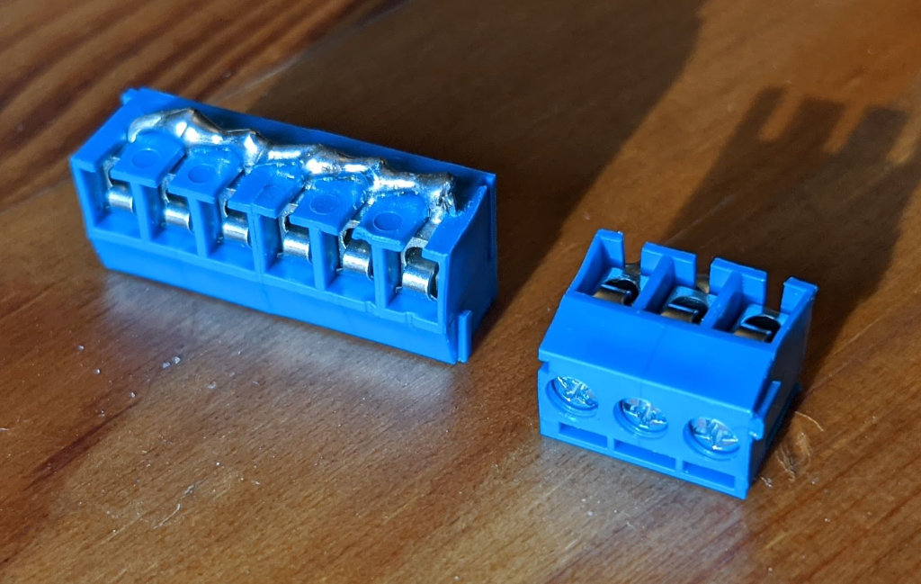
To fix the 24VAC conductors, I took several 3.5 mm screw terminal blocks (TE 1776275-6), bent the contacts to the sides and soldered them in the form of a bus. Bare metal wrapped with duct tape.
This is what the complete thermostat housing looks like, including the 24VAC to 5VDC power supply at the bottom. I decided to use MicroUSB so that I could not forget to turn off the power before reprogramming.

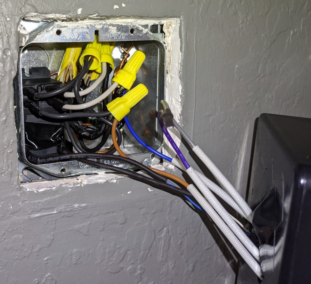
The back box originally contained a 208VAC thermostat for skirting board heating. I added a white-wired Schneider Electric 92S7A22D-24 relay that Nest defines as "aux heat". In fact, a relay and a transformer are the only components required to use the Nest as a mains powered thermostat.
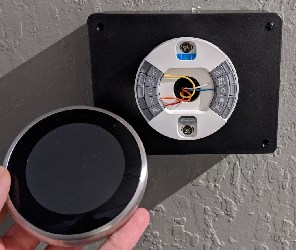
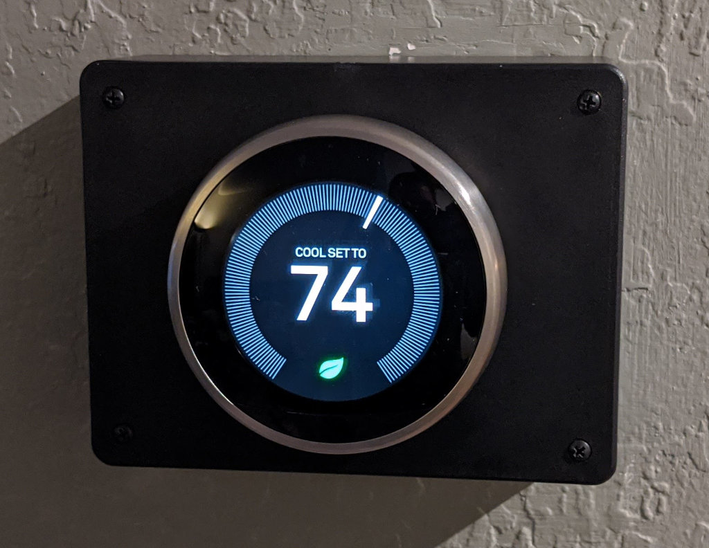
Here's what Nest looked like at different stages of the build:

Source
https://github.com/pmarks-net/ac/
Video
- Lighting Level Monitoring (06/07/2020): https://www.youtube.com/watch?v=C5tmRAij6e0
- 24VAC indicator (06/17/2020): https://www.youtube.com/watch?v=C4kNbceWMxM
- System demo (07/12/2020): https://www.youtube.com/watch?v=_ziA3l_pd60