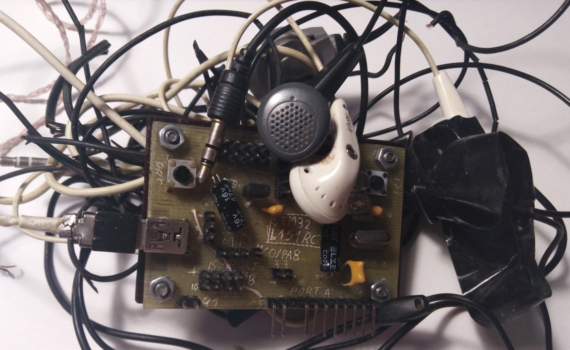
 <picture with board and headphones>
Even lower level (avr-vusb): habr.com/ru/post/460815
USB on registers: STM32L1 / STM32F1
USB on registers: bulk endpoint using the example of Mass Storage
USB on registers: interrupt endpoint on HID example
Today, let's look at the last type of endpoint, isochronous. It is designed to transfer data critical to delivery time, but does not guarantee its success. The most classic example is audio devices: speakers, microphones.
Oddly enough, this type of endpoint turned out to be the most brain-pumping (and this is after everything I've seen with stm'ki!). Nevertheless, today we will make an audio device and at the same time slightly finish the core of the USB library. As usual, the source codes are available:
github.com/COKPOWEHEU/usb/tree/main/4.Audio_L1
github.com/COKPOWEHEU/usb/tree/main/4.Audio_F1
Kernel refinement
It is necessary to refine the kernel because STM can only have isochronous points with double buffering, that is, roughly speaking, it is impossible to make 0x01 isochronous, and 0x81 control. That is, it is, of course, possible to write this in the USB descriptor, but this will not change the inside of the controller, and the real address of the point will simply differ from the one visible from the outside. Which, of course, will increase the risk of mistakes, so we will not be perverted in this direction.
It should be noted that double buffering occurs not only for isochronous points, but also for bulk, and it turns on and works differently. If isochronous points enable buffering automatically, simply because they cannot do otherwise, then for the corresponding bulk setting, you have to use the special USB_EP_KIND bit, which must be set along with the actual point type setting.
By itself, buffering means that if before one point corresponded to one buffer for transmission and one for reception, now both buffers will work either for transmission or reception, and they will only work together. As a result, the setting of a buffered point is very different from the usual one, because you need to set up not one buffer, but two. Therefore, we will not sculpt unnecessary conditions into the usual initialization, but create a separate function usb_ep_init_double () based on it.
Reception and transmission of packets does not differ so much, although it took much more time first to try to understand how it should work according to the ST logic, then to adjust the spell from the Internet to make it work. As mentioned earlier, if for an ordinary point two buffers are independent and differ in the direction of exchange, then for a buffered one they are the same and differ only in offset. So let's change the usb_ep_write and usb_ep_read functions a little so that they accept not a point number, but an offset number. That is, if earlier these functions assumed the existence of eight double points, now - 16 single ones. Accordingly, the number of the new "half-line" for writing is only equal to the number of the usual one, multiplied by two, and for usb_ep_read one must also add one (see the allocation of buffers in the PMA). Actually,this is done by the inline functions usb_ep_write and usb_ep_read for regular points. But let's take a closer look at the buffered logic.
According to the documentation, one buffer of such a point is available for hardware, the second for software. Then they switch and again do not interfere with each other. For the OUT point, the flag on the hardware side is the USB_EP_DTOG_RX bit, which needs to be read in order to understand which of the buffers has just finished writing and from where the software can read, respectively. When he read his buffer, you need to jerk the USB_EP_DTOG_TX bit, which actually switches the buffers. Not sure if this is what is meant, but at least it works.
A symmetrical situation should have been with IN points. But in practice, it turned out that you need to check and pull USB_EP_DTOG_RX. Why not TX I still do not understand ... Thanks to the user kuzulis for the link to github.com/dmitrystu/libusb_stm32/edit/master/src/usbd_stm32f103_devfs.c
Due to the function inline, no special overhead was added, apart from initialization. But you can, if you wish, throw it out with the linker flags. Or you don't need to throw it out: it doesn't take up so much space, and it is called only during initialization. This is not a HAL for you, where functions are not only heavy, but also call each other all the time.
As a result, the endpoints have learned to work in buffered mode ... if you don't breathe too hard on them.
For the user, the difference is small: instead of usb_ep_init, use usb_ep_init_double, and instead of usb_ep_write and usb_ep_read, use usb_ep_write_double and usb_ep_read_double, respectively.
AudioDevice device
And now, when we figured out the technical rake, let's move on to the most interesting thing - setting up an audio device.
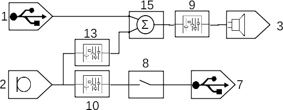
According to the USB standard, an audio device is a set of entities connected to each other in a certain topology, through which the audio signal passes. Each entity has its own unique number (bTerminalID, aka UnitID), by which other entities or endpoints can connect to it, the host also uses it if it wants to change some parameters. And he is considered the only way out of this entity. But there may be no inputs at all (if it is an input terminal), or there may be more than one (bSourceID). Actually, by writing the numbers of the entities from which the current one receives an audio signal to the bSourceID array, we describe the entire topology, which as a result can turn out to be very quick. As an example, I will give the topology of a purchased USB sound card (the numbers show bTerminalID / UnitID):
lsusb and its decryption
Bus 001 Device 014: ID 0d8c:013c C-Media Electronics, Inc. CM108 Audio Controller

#
Device Descriptor:
  bLength                18
  bDescriptorType         1
  bcdUSB               1.10
  bDeviceClass            0
  bDeviceSubClass         0
  bDeviceProtocol         0
  bMaxPacketSize0         8
  idVendor           0x0d8c C-Media Electronics, Inc.
  idProduct          0x013c CM108 Audio Controller
  bcdDevice            1.00
  iManufacturer           1
  iProduct                2
  iSerial                 0
  bNumConfigurations      1

#
  Configuration Descriptor:
    bLength                 9
    bDescriptorType         2
    wTotalLength       0x00fd
    bNumInterfaces          4  #
    bConfigurationValue     1
    iConfiguration          0
    bmAttributes         0x80
      (Bus Powered)
    MaxPower              100mA

# 0 -
    Interface Descriptor:
      bLength                 9
      bDescriptorType         4
      bInterfaceNumber        0
      bAlternateSetting       0
      bNumEndpoints           0
      bInterfaceClass         1 Audio
      bInterfaceSubClass      1 Control Device
      bInterfaceProtocol      0
      iInterface              0
      AudioControl Interface Descriptor:
        bLength                10
        bDescriptorType        36
        bDescriptorSubtype      1 (HEADER)
        bcdADC               1.00
        wTotalLength       0x0064
        bInCollection           2  # !    (2)
        baInterfaceNr(0)        1  #
        baInterfaceNr(1)        2  #

#####  #####
# 1 InputTerminal (USB,  )
      AudioControl Interface Descriptor:
        bLength                12
        bDescriptorType        36
        bDescriptorSubtype      2 (INPUT_TERMINAL)
        bTerminalID             1  #
        wTerminalType      0x0101 USB Streaming
        bAssocTerminal          0
        bNrChannels             2  #
        wChannelConfig     0x0003  #   -
          Left Front (L)
          Right Front (R)
        iChannelNames           0
        iTerminal               0

# 2 InputTerminal ()
      AudioControl Interface Descriptor:
        bLength                12
        bDescriptorType        36
        bDescriptorSubtype      2 (INPUT_TERMINAL)
        bTerminalID             2
        wTerminalType      0x0201 Microphone
        bAssocTerminal          0
        bNrChannels             1
        wChannelConfig     0x0001
          Left Front (L)
        iChannelNames           0
        iTerminal               0

# 6 OutputTerminal (),     9
      AudioControl Interface Descriptor:
        bLength                 9
        bDescriptorType        36
        bDescriptorSubtype      3 (OUTPUT_TERMINAL)
        bTerminalID             6
        wTerminalType      0x0301 Speaker
        bAssocTerminal          0
        bSourceID               9  #
        iTerminal               0

# 7 OutputTerminal (USB),     8
      AudioControl Interface Descriptor:
        bLength                 9
        bDescriptorType        36
        bDescriptorSubtype      3 (OUTPUT_TERMINAL)
        bTerminalID             7
        wTerminalType      0x0101 USB Streaming
        bAssocTerminal          0
        bSourceID               8
        iTerminal               0

# 8 Selector,      10
      AudioControl Interface Descriptor:
        bLength                 7
        bDescriptorType        36
        bDescriptorSubtype      5 (SELECTOR_UNIT)
        bUnitID                 8
        bNrInPins               1  #
        baSourceID(0)          10  #
        iSelector               0

# 9 Feature,     15
      AudioControl Interface Descriptor:
        bLength                10
        bDescriptorType        36
        bDescriptorSubtype      6 (FEATURE_UNIT)
        bUnitID                 9
        bSourceID              15
        bControlSize            1
        bmaControls(0)       0x01
          Mute Control
        bmaControls(1)       0x02
          Volume Control
        bmaControls(2)       0x02
          Volume Control
        iFeature                0

# 10 Feature,     2
      AudioControl Interface Descriptor:
        bLength                 9
        bDescriptorType        36
        bDescriptorSubtype      6 (FEATURE_UNIT)
        bUnitID                10
        bSourceID               2
        bControlSize            1
        bmaControls(0)       0x43
          Mute Control
          Volume Control
          Automatic Gain Control
        bmaControls(1)       0x00
        iFeature                0

# 13 Feature,     2
      AudioControl Interface Descriptor:
        bLength                 9
        bDescriptorType        36
        bDescriptorSubtype      6 (FEATURE_UNIT)
        bUnitID                13
        bSourceID               2
        bControlSize            1
        bmaControls(0)       0x03
          Mute Control
          Volume Control
        bmaControls(1)       0x00
        iFeature                0

# 15 Mixer,     1  13
      AudioControl Interface Descriptor:
        bLength                13
        bDescriptorType        36
        bDescriptorSubtype      4 (MIXER_UNIT)
        bUnitID                15
        bNrInPins               2  #
        baSourceID(0)           1  #
        baSourceID(1)          13
        bNrChannels             2
        wChannelConfig     0x0003
          Left Front (L)
          Right Front (R)
        iChannelNames           0
        bmControls(0)        0x00
        iMixer                  0
#####   #####

#  1 () -
    Interface Descriptor:
      bLength                 9
      bDescriptorType         4
      bInterfaceNumber        1
      bAlternateSetting       0
      bNumEndpoints           0
      bInterfaceClass         1 Audio
      bInterfaceSubClass      2 Streaming
      bInterfaceProtocol      0
      iInterface              0

#  1 () -
    Interface Descriptor:
      bLength                 9
      bDescriptorType         4
      bInterfaceNumber        1
      bAlternateSetting       1
      bNumEndpoints           1
      bInterfaceClass         1 Audio
      bInterfaceSubClass      2 Streaming
      bInterfaceProtocol      0
      iInterface              0
      AudioStreaming Interface Descriptor:
        bLength                 7
        bDescriptorType        36
        bDescriptorSubtype      1 (AS_GENERAL)
        bTerminalLink           1
        bDelay                  1 frames
        wFormatTag         0x0001 PCM
      AudioStreaming Interface Descriptor:
        bLength                14
        bDescriptorType        36
        bDescriptorSubtype      2 (FORMAT_TYPE)
        bFormatType             1 (FORMAT_TYPE_I)
        bNrChannels             2
        bSubframeSize           2
        bBitResolution         16
        bSamFreqType            2 Discrete
        tSamFreq[ 0]        48000
        tSamFreq[ 1]        44100
      Endpoint Descriptor:
        bLength                 9
        bDescriptorType         5
        bEndpointAddress     0x01  EP 1 OUT
        bmAttributes            9
          Transfer Type            Isochronous
          Synch Type               Adaptive
          Usage Type               Data
        wMaxPacketSize     0x00c8  1x 200 bytes
        bInterval               1
        bRefresh                0
        bSynchAddress           0
        AudioStreaming Endpoint Descriptor:
          bLength                 7
          bDescriptorType        37
          bDescriptorSubtype      1 (EP_GENERAL)
          bmAttributes         0x01
            Sampling Frequency
          bLockDelayUnits         1 Milliseconds
          wLockDelay         0x0001

#  2 () -
    Interface Descriptor:
      bLength                 9
      bDescriptorType         4
      bInterfaceNumber        2
      bAlternateSetting       0
      bNumEndpoints           0
      bInterfaceClass         1 Audio
      bInterfaceSubClass      2 Streaming
      bInterfaceProtocol      0
      iInterface              0

#  2 ()
    Interface Descriptor:
      bLength                 9
      bDescriptorType         4
      bInterfaceNumber        2
      bAlternateSetting       1
      bNumEndpoints           1
      bInterfaceClass         1 Audio
      bInterfaceSubClass      2 Streaming
      bInterfaceProtocol      0
      iInterface              0
      AudioStreaming Interface Descriptor:
        bLength                 7
        bDescriptorType        36
        bDescriptorSubtype      1 (AS_GENERAL)
        bTerminalLink           7
        bDelay                  1 frames
        wFormatTag         0x0001 PCM
      AudioStreaming Interface Descriptor:
        bLength                14
        bDescriptorType        36
        bDescriptorSubtype      2 (FORMAT_TYPE)
        bFormatType             1 (FORMAT_TYPE_I)
        bNrChannels             1
        bSubframeSize           2
        bBitResolution         16
        bSamFreqType            2 Discrete
        tSamFreq[ 0]        48000
        tSamFreq[ 1]        44100
      Endpoint Descriptor:
        bLength                 9
        bDescriptorType         5
        bEndpointAddress     0x82  EP 2 IN
        bmAttributes            9
          Transfer Type            Isochronous
          Synch Type               Adaptive
          Usage Type               Data
        wMaxPacketSize     0x0064  1x 100 bytes
        bInterval               1
        bRefresh                0
        bSynchAddress           0
        AudioStreaming Endpoint Descriptor:
          bLength                 7
          bDescriptorType        37
          bDescriptorSubtype      1 (EP_GENERAL)
          bmAttributes         0x01
            Sampling Frequency
          bLockDelayUnits         0 Undefined
          wLockDelay         0x0000
#####    #####

#  3 "    " ( )
    Interface Descriptor:
      bLength                 9
      bDescriptorType         4
      bInterfaceNumber        3
      bAlternateSetting       0
      bNumEndpoints           1
      bInterfaceClass         3 Human Interface Device
      bInterfaceSubClass      0
      bInterfaceProtocol      0
      iInterface              0
        HID Device Descriptor:
          bLength                 9
          bDescriptorType        33
          bcdHID               1.00
          bCountryCode            0 Not supported
          bNumDescriptors         1
          bDescriptorType        34 Report
          wDescriptorLength      60
         Report Descriptors:
           ** UNAVAILABLE **
      Endpoint Descriptor:
        bLength                 7
        bDescriptorType         5
        bEndpointAddress     0x87  EP 7 IN
        bmAttributes            3
          Transfer Type            Interrupt
          Synch Type               None
          Usage Type               Data
        wMaxPacketSize     0x0004  1x 4 bytes
        bInterval               2
We are going to do something simpler (I took the blank from here ):
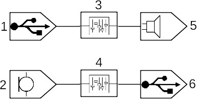
Here you can see two independent signal propagation branches: either from USB through a “feature” to a “speaker”, or from a “microphone” through another “feature” to USB. The microphone and speaker are not just put in quotes: they are not on my debug board, so instead of the sound itself, we will use buttons and LEDs. However, nothing new. "Features" in my case do nothing and are added more for beauty.
It should be clarified right away that the signal in this model is considered to be composed of one or more logical channels. That is, if, for example, I change a mono speaker to a stereo one, the topology itself will remain unchanged, only the signal format will change.
I have not dug deep into the differences between the kinds of "features" and other entities, but I will not disdain to retell a piece of documentation.
1. Input Terminal
As the name suggests, it is through it that the audio signal enters the audio device. It can be USB, it can be an ordinary microphone, a headset microphone, even a microphone array.
2. Output Terminal
It is also quite obvious - that through which the sound leaves our device. It can be the same USB, it can be a speaker, a headset, a speaker in the monitor, speakers of various frequencies, and a bunch of other devices.
3. Mixer Unit
It takes several input signals, amplifies each one by a predetermined amount and adds the result to the output channel. If desired, you can set the gain to zero, which will reduce it to the next entity.
4. Selector Unit
Takes multiple input signals and redirects one of them to the output.
5. Filter (Feature Unit)
Takes a single input signal, changes the sound parameters (volume, tone, etc.) and outputs it to the output. Naturally, all these parameters are applied to the entire signal in the same way, without the interaction of logical channels within it
6. Processing Unit
But this thing already allows you to manipulate individual logical channels within each input. Moreover, it allows you to make the number of logical channels in the output not equal to the number in the input.
7. Extension Unit
The whole set of non-standard entities, so that the sick fantasy of equipment manufacturers was free. Accordingly, both behavior and settings will depend on this very fantasy.
Some entities have parameters like gain or channel number, which can be influenced by the host using setFeature / getFeature queries on the entity number. But here, to be honest, I don't really understand how to check it at all. Probably, you need some kind of special software, which I do not have. Well, okay, anyway I got into it just to check all types of points ... on my head ...
Rake in the descriptor
Unlike previous USB devices, the descriptor here is complex, layered and tends to scare Windows into BSOD. As we saw above, the topology of an autologous device can be quite complex and spreading. An entire interface stands out for its description. Obviously, it will not contain endpoints, but it will contain a list of entity descriptors and descriptions of what their inputs are connected to. I don't see much sense here, it's easier to look at the code and documentation. I will only note the main rake: here it is described which interfaces with the corresponding endpoints refer specifically to this device. For example, if you want to change my configuration and remove the speaker from there, you will not only have to delete half of the entities (thank the macros, at least there will be no problem with calculating the length of the descriptor), but also reduce the bInCollection field to 1,then remove the number of the extra interface from the array bInterfaceNr following it.
Further there are interfaces responsible for data exchange. In my case, the 1st interface is responsible for the microphone, and the 2nd for the speaker. It is worth paying attention here, first of all, to two variants of each of these interfaces. One with bAlternateSetting equal to 0, the second with 1. They differ in the presence of an endpoint. That is, if our device is not currently in use, the host simply switches to the alternative interface that is not equipped with the endpoint, and no longer wastes the bus bandwidth on it.
The second feature of data interfaces is the audio signal format. The corresponding descriptor specifies the encoding type, number of channels, resolution and sampling rate (which is specified by a 24-bit number). There are quite a few coding options, but we will use the simplest one - PCM. In fact, it is just a sequence of values of the instantaneous value of the signal without any coding, and the value is considered a signed integer . The signal resolution is set in two places (it's not clear why): the bSubFrameSize field specifies the number of bytes , and bBitResolution specifies the number of bits... It can probably be pointed out that the range of our sound card does not go up to the full range of the data type, say int16_t and is only 10 bits.
And finally, the descriptor of the actual endpoint. It also differs slightly from the usual ones, since it provides, firstly, several synchronization options, and secondly, the number of the entity with which this point is associated (bTerminalLink) . Synchronization options are written in high-order bits directly into the endpoint type (which is why the isochronous point is moved to the default branch in the initialization function), but I haven’t dealt with their details, so I can’t tell you anything interesting. Instead of synchronization, we will use a regular controller timer, which will generate interrupts at approximately the desired frequency.
Oh yeah, I almost forgot to mention another bunch of BSODs when testing the wrong descriptors. Let me remind you once again: the number of data interfaces must correspond to the number of bInCollection, and their numbers must correspond to the array following it!
Hidden text
, , . --.
The logic of the device
As I already said, for tests it makes no sense to fence hinged components on the debug board, so all testing will be carried out with what has already been installed - buttons and LEDs. However, in this case, this does not constitute a problem: the "microphone" can simply generate a sinusoid with a frequency of, say, 1 kHz, and the "speaker" turn on the LED when the sound threshold value is exceeded (say, above 10,000: with the specified 16 bits of resolution, which corresponds range -32768 ... +32767, this is about a third).
But with testing, there was a small problem: I did not find an easy way to redirect the signal from the microphone to the stdin of some program. It seems that earlier this was done simply by reading / dev / dsp, but now something has broken. However, nothing critical, because there are all sorts of libraries for interaction with multimedia - SDL, SFLM and others. Actually in SFML I wrote a simple utility for reading from a microphone and, if necessary, visualizing the signal.
I will pay special attention to the limitations of our audio device: as far as I understand, an isochronous IN request is sent once per millisecond (but there can be many OUTs), which limits the sampling rate. Let's say the size of the endpoint is 64 bytes (taking into account buffering, it takes 128 bytes in memory, but the host does not know about it), the resolution is 16 bits, that is, 32 samples can be sent at a time. Given a 1 ms interval, we get a theoretical limit of 32 kHz for one channel. The easiest way to get around this is to increase the size of the endpoint. But here we must remember that the size of the total PMA buffer is only 512 bytes. Minus the point distribution table, minus ep0, we get a maximum of 440 bytes, that is, 220 bytes per single point, taking into account buffering. And this is the theoretical limit.
But the fact that the host can send several OUT requests in one frame suggests that the device can do the same. It remains to understand how. Perhaps this is solved by a competent synchronization setting. But for me this question is no longer of interest: the isochronous points work, the buffered points work, the audio device works - the task is completed.
Conclusion (common for the cycle)
Well, we got acquainted with the USB device in STM32F103 and STM32L151 controllers (and others with a similar implementation), were surprised at the logic of some architectural solutions (I was especially impressed by the USB_EPnR register, however, double buffering is also not lagging behind), examined all types of endpoints and checked them, by building the appropriate devices. So we can say that this series of articles has come to a logical conclusion. Although this, of course, does not mean that I will abandon controllers or USB: in the distant plans, I still have to deal with composite devices (so far it looks easy, but after all, isochronous points also did not bode well) and USB on controllers of other families.