This is not my first project to develop a laptop battery charger. Note that in the first project I used Max1873. But to control the charge, I had to use an ATtiny microcontroller. All would be fine, but here it was required to write specific code, which complicated the project.
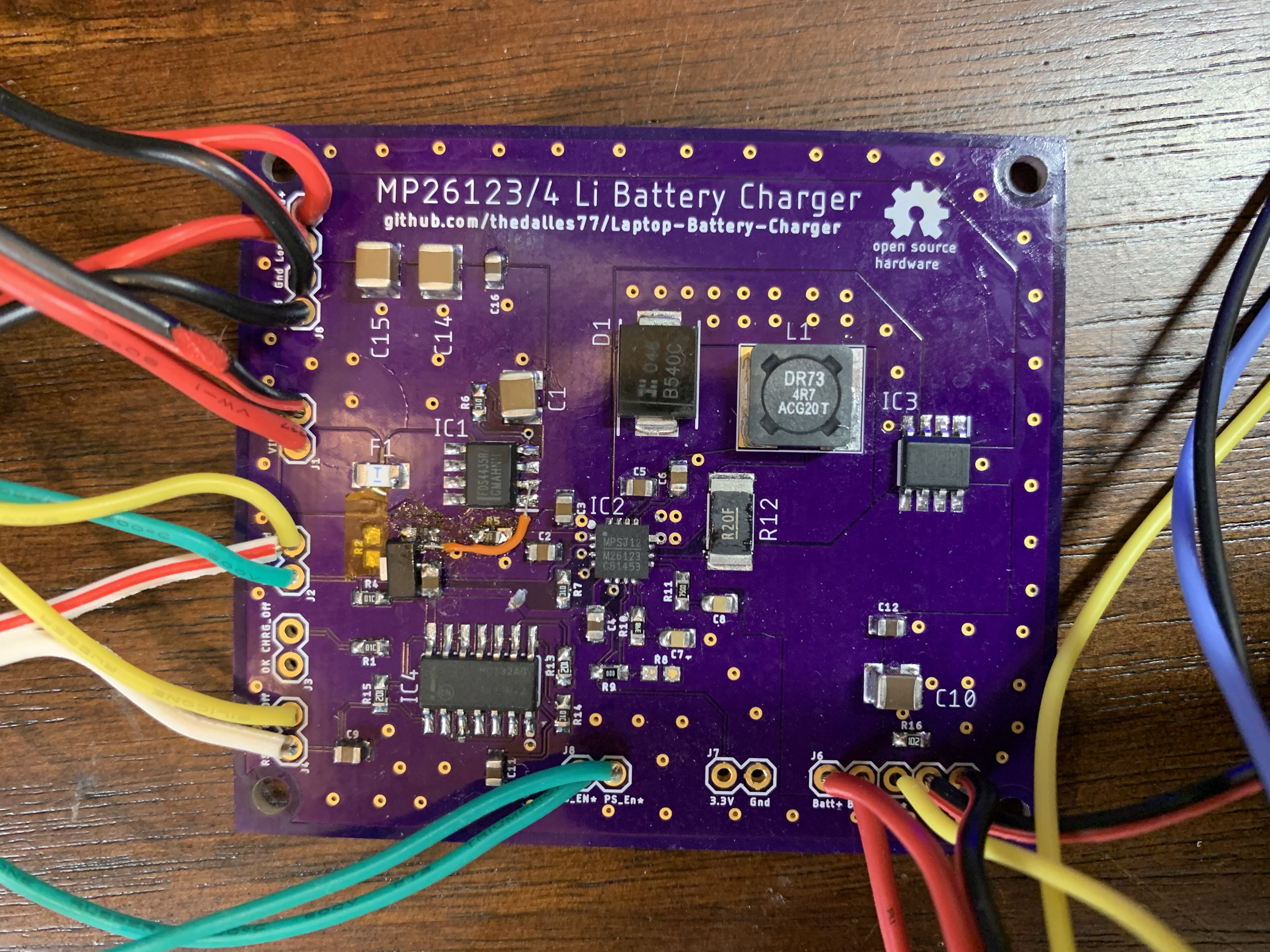
The second project is based on the MP26123 or MP26124 from Monolithic Power Systems. These chips make it possible to charge a discharged battery, stop charging when the charge level reaches 100%, discharge an already charged battery, and control its temperature. Another advantage of the controllers is that the main FET switch is located inside, which reduces the complexity of the layout. An example of an assembled board is at the very beginning of the article. Well, under the cut we will discuss the details of the project.
Details of the project
For the development of the board, I studied the specification of the MP26123 and MP26124 controllers. The designations of the elements that are needed for the board are shown in the diagram below. There is also a source file if you want to change the board design .

An important point: the controllers do not reduce the charge current, do not limit the input current. But there is a 5A fuse on the board. Instead of the traditional Schottky diode for many boards, I use a PFET to reduce heat. A PFET instead of a diode is also used to avoid using the 0.4V voltage drop across the diode. This is important as the near-full 3-cell battery barely has enough energy to light up the laptop screen. The MP26123 / MP26124 controllers power the load of the LM2596 buck regulator either from the battery or from the 19V input. There are no voltage drops when connecting or disconnecting the power supply. The MP26123 / MP26124 enable pin is at the very edge of the board, so the Pi can turn off charging if needed.
The idle SR latch is always energized to activate the buck regulator load. This is required if the power pushbutton switch is turned on. The SR latch is powered by a 3.3V linear regulator or a 19V input power supply. The current drawn by the battery with the buck regulator off load is 315 μA. An internal battery self-discharge of 2% plus a 3% loss due to protective circuitry results in a complete battery discharge in 324 days. If you are not planning to use the laptop all this time, it is best to simply remove the battery. In this case, a self-discharge of 2% will lead to a complete discharge of the battery after about two years (provided, of course, that the battery was 100% charged when removed).
If the battery voltage drops below 3V for one cell, the MP26123 / MP26124 controllers will precharge for 30 minutes, reducing the current to 10% of the charge current. Thanks to resistor R12, I reduced the total charge current to 1A. According to the specification, the controllers can handle 2A, but I didn't want to overload the system. As soon as the battery voltage reaches the maximum level, the charger will enter standby mode (at 10% of the rated current) and then shut down.
The maximum charging time is set at 4.5 hours with a C6 capacitor of 0.15 μF. The time value can be changed by changing the capacitance of the capacitor - for this there is a data table with a formula. If required, a 10K NTC battery thermistor can be connected to the power controller to shut off the charge current when the temperature rises or falls to a predetermined level. By default, the trip will be performed at 40 ° C (high) or 11 ° C (low). If you do not connect a thermistor, then set the resistor to 10K to emulate room temperature.
Unfortunately, the MP26123 / MP26124 controllers have a number of disadvantages. So, they can only be used to charge the cells of lithium batteries with the voltage of each cell not exceeding 4.2V. Old batteries, where the value was 4.1V, and new ones with 4.35V cells, cannot be charged with this device. But if you install the Max1873 controller, then there are no problems.
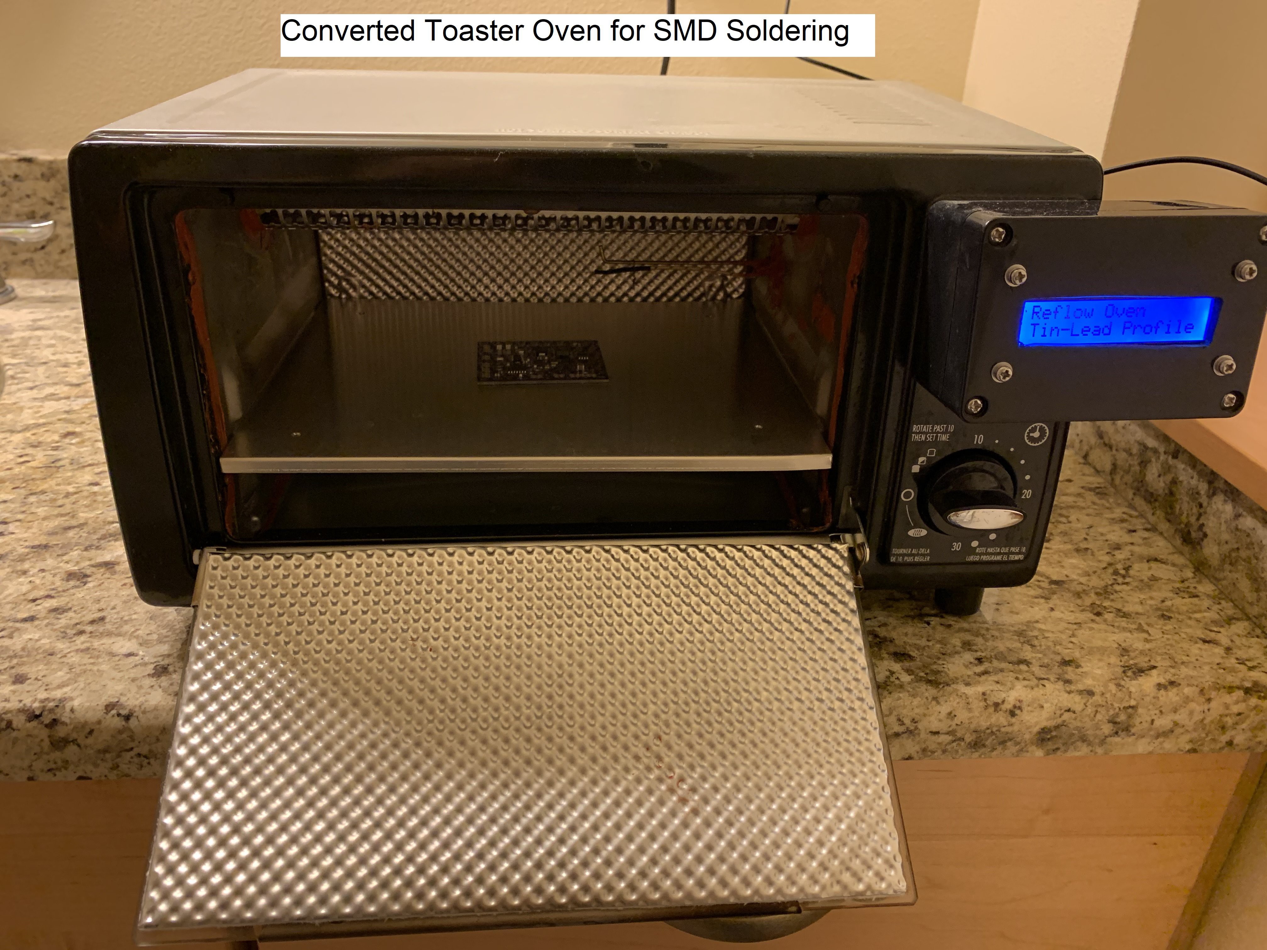
As for soldering the controllers, I used a homemade oven, but of course it is better to use a hot air soldering station to assemble the board.
Features of the board
The width of the tracks on the board is designed for a current of at least 3A. Several options were tested, in the end it was decided to stop at a minimum track width of 5 mm. In the first version of the board, 3.3V from MP26123 was used for SR latch, which was activated only when plugged into an outlet. The updated design includes a separate 3.3V linear regulator that keeps the SR latch operational with or without power. The dimensions of the board are 62 mm * 54 mm.

In terms of price, the three boards made by OSHPark.com cost me $ 26 shipping by USPS. You can also use JLCPCB.com, for this use the archive file MPS_Charge_Controller_2021-02-23.zip . Five boards will cost the customer $ 10 with standard shipping.
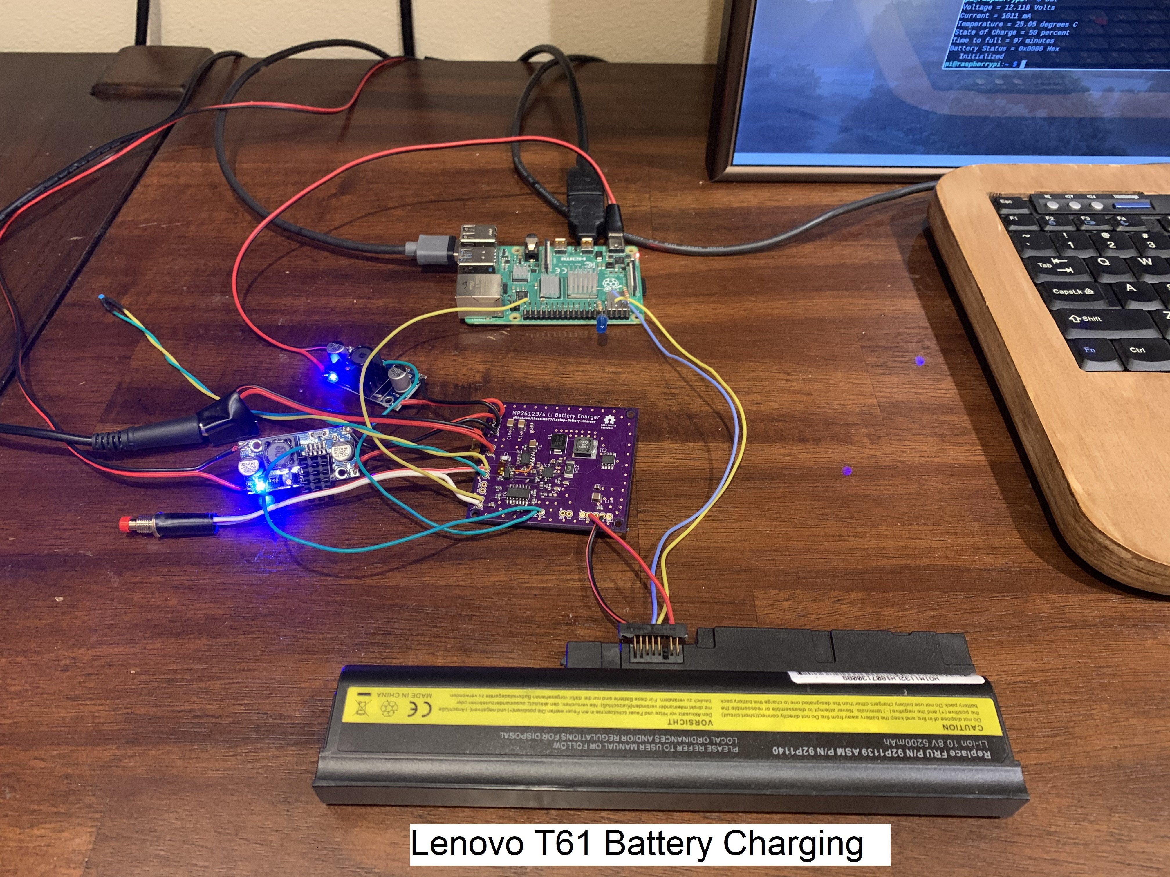
The graph below shows the test results of an MP26123 charging a 3S2P battery from a Lenovo T61.


I also posted instructions on Instructables showing how to connect the battery charger board to the Pi, Teensy, and graphics card. The tutorial explains how to use a battery powered Raspberry Pi in a modified laptop. There is also attached a C code that controls communication with the battery via the SMBus, displaying charge level indicators and turning off the laptop when it is discharged.