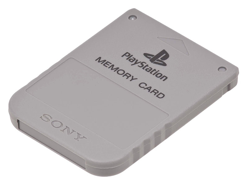
PS1 (aka PSX, aka PS One) is the first generation of Sony's PlayStation game consoles and belongs to the fifth generation of game consoles in general. It uses a 2x speed drive to read CDs. Such a large amount of data, by the standards of the current time for the console, allowed game developers not to particularly look back at the restrictions when creating content for games, which made the latter of higher quality compared to the games of the previous generation of consoles. Also, games can now be long. And if any game, with rare exceptions, on consoles of previous generations could well be completed in one game session, then with PS1 games everything was different. To save progress, PlayStation has memory cards: small, removable non-volatile memory modules.
If you are wondering exactly how the PlayStation 1 memory card works, how it works, and how you can create your own, welcome to cat.
So, the PS1 memory card is a standard peripheral device, like the whole zoo of joypads, joysticks and other accessories. To understand exactly how it works, you first need to look at what it has inside.
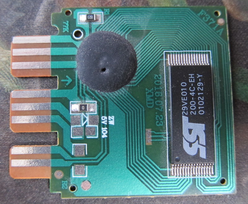
Photo of the printed circuit board of a standard 15-block memory card
As you can see from the photo, the device of the card is very simple: a controller that serves system requests, and, in fact, non-volatile memory, which is represented by the standard NOR FLASH. Logically, the memory card is split into 15 blocks that games can use. It may seem that 15 is not logical for a binary system, but there is no contradiction here: one block is given for the file system, file names and even animated icons are stored there, just like NTFS streams. Each block has a size of 8 KiB, 16 blocks in total is 128 KiB, which can be seen from the marking of the FLASH memory in the photo above.
At first, this was enough for everyone, but then games began to appear that used more than one block at a time. For example, some simulators, like Sega GT, use 4-5 blocks, while Constructorso in general the whole memory card is 15 blocks. This forced to buy more cards and the situation threatened to become like floppy disks or cartridges. But then the pirates pulled up and began to issue cards for 2, 4 or 8 pages at once. And the pages were switched either by a clever combination on the joypad, or by an explicit button on the memory card itself. However, in cards with more than 2 pages, compression was used, and the actual number of pages was much less, and some cards could be stupidly blocked. And it was very difficult to get them out of this state, but what the players did not go to for the sake of their saves. Here are typical representatives of multi-page memory cards:
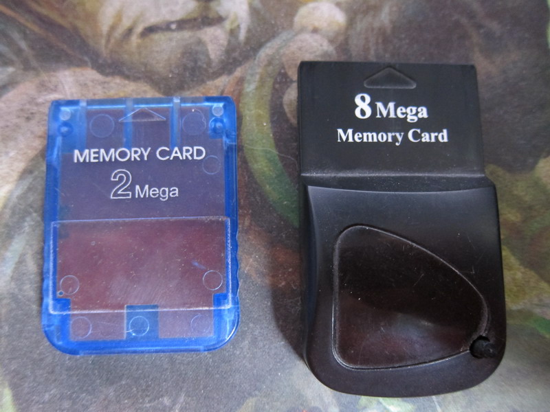
On the left is a memory card with 2 pages, on the right with 8. The right one has a hardware page turning button and an indicator showing the number from 1 to 8, which is hidden behind a dark glass
Small lyrical digression
It all started in 2001, when I bought a miracle disk for PC called "All Emulators", on which there were PS1 emulators including: it was Bleem! and early ePSXe. And my then computer was even able to play my PS1 disks playably! And a little later I got a modem and I learned about DirectPad Pro . Connecting a native joystick to a computer (albeit via LPT) costs a lot. And this system worked on both 9x and XP! And a little later, already in 2002, I learned about Memory Card Capture Sakura! This program allowed working with real memory cards using the same DirectPad Pro connection scheme. It was then that I got the idea to make an "endless" memory card that would allow me to exchange information with a computer without the need for additional devices. But at that time I did not have enough information and available element base, and the idea remained just an idea, glimmering somewhere in the backyard of my consciousness.
Almost 9 years have passed since I realized that I already know enough and have the opportunity to implement at least some version of an endless memory card. However, another factor came into play here - age and everything connected with it. There is less time for hobbies, more and more worries. And only now can I provide the public with at least some result, a full-fledged Proof of Concept.
Physical interface
So, the memory card and joypads work through a common interface. The number of signals in it is 6, here are their names and purposes:
- SEL0 - First port select signal, active level low
- SEL1 - Second port selection signal, active level low;
- CLK - The clock signal of the interface, passive state high level, on the falloff shift, on the edge latching;
- CMD - Data signal from the console to the periphery;
- DAT - Data signal from the periphery to the console;
- ACK - Hardware handshake, active low.
There are also two different supply voltages on the interface: 3.3v and 7.6v. All signals except SEL0 and SEL1 are common to all connected devices. That is why a non-working memory card or a joypad in the second slot affected the workers in the first one, although after 16-bit consoles it seemed strange. I think that many have already recognized the standard SPI in the interface - everything is correct, it is. Only added an ACK signal to confirm the I / O operation. Here are the assignments of the signals on the contacts of the memory card:
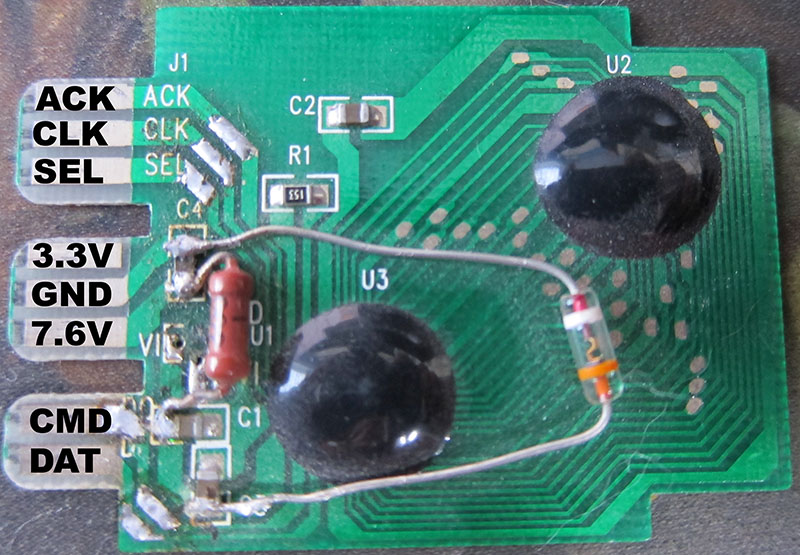
Repaired memory card with 5 volt FLASH The
technical characteristics of the interface are as follows:
        ___ ___________________________ ____
     \ /                           \ /
         X                             X
 ___/ \___________________________/ \____
        ___                  ____________
           \                /            \
       \              /              \
             \____________/                \____
            |                             |
            |           tck               |
            |<--------------------------->|

+-------+-------+------+-------+
|       | .  | . | . |
+-------+-------+------+-------+
| tck   | 1  | 4 |   -   |
+-------+-------+------+-------+

 ACK:
     ____
SEL-     |______________________________________________
     ______        __________        ___________
CLK        ||||||||          ||||||||           ||||||||
                  |                 |
ACK- -----------------------|_|-------------|_|---------
                  |   ta1   | |     |  ta2  |
                  |<------->| |     |<----->|
                            | |  ap
                           >|-|<-----

+-----+------+-------+--------+
|     | . |  . |  . |
+-----+------+-------+--------+
| ta1 | 0 |   -   | 100 |  -
+-----+------+-------+--------+
| ta2 |      | 10 |   1  |
+-----+------+-------+--------+
|  ap | 2 |       |        |  ACK
+-----+------+-------+--------+
The measured frequency of the CLK signal is 250 kHz, which is 4 µs per cycle. With the physical parameters of the interface sorted out, now the transport layer. An experienced engineer has already noticed that the joypad and memory card are connected completely in parallel and may conflict with each other. Indeed, there is software arbitration for this. After the SELn signal is activated, the periphery remains silent, but listens to the first byte sent. If this byte is equal to 0x01, then the joypad is activated, and the memory card remains silent until the selection signal is deactivated. And if the byte was 0x81, then the opposite is true: the memory card is activated, and the joypad is silent. Naturally, the host is waiting for an ACK signal on this byte of arbitration and does not wait long. This is necessary in order to have time to interrogate the rest of the periphery, if part of this periphery is absent. The fact is that the operating system polls the controllers and memory cards strictly according to the signal of the return path of the beam, or better known as VBlank . It is so accepted that games in consoles up to the 5th generation are tied to this timing, which is equal to the frame rate. And the frame rate is strictly stable and normalized: 50Hz for PAL and 60Hz for NTSC. That is, the polling period for joysticks and memory cards is 20ms for PAL or 16ms for NTSC.
So, we figured out the arbitration, now the actual top level. What commands does the standard PS1 memory card understand? Yes, in fact, there are only 3 of them.
- R - 0x52 or Read . Reading a sector of a memory card;
- W - 0x57 or Write . Memory card sector recording;
- S - 0x53 or Status . Reading the status of the memory card.
The entire memory card is divided into sectors. One sector of 128 bytes. Thus, 128KiB fits 0x400 or 1024 sectors. In this case, you do not need to erase the sector before recording. But the system is guaranteed to give time for the next whole frame when recording. That is, it can read the memory card every frame, but writes it after one. By the way, all sorts of "Codebreakers" do not adhere to these timings to speed up. Let's analyze each command in more detail.
Memory card protocol
The order of the transmitted data in each command looks like this:
Reading:
CMD 0x81 0x52 0x00 0x00 MSB LSB 0x00 0x00 0x00 0x00 0x00 ... 0x00 0x00 0x00
DAT ---- FLAG 0x5A 0x5D PRV PRV 0x5C 0x4D  MSB  LSB DATA ... DATA  CHK  ACK
:
CMD 0x81 0x57 0x00 0x00 MSB LSB DATA ... DATA CHK 0x00 0x00 0x00
DAT ---- FLAG 0x5A 0x5D PRV PRV  PRV ...  PRV PRV 0x5C 0x5D  ACK
:
CMD 0x81 0x53 0x00 0x00 0x00 0x00 0x00 0x00 0x00 0x00
DAT ---- FLAG 0x5A 0x5D 0x5C 0x5D 0x04 0x00 0x00 0x80
Legend:
CMD - Data that the host sends to the card.
DAT - Data that the card sends to the host.
FLAG - Current flags of the map state and the result of the previous command.
PRV - Previous received data, the result of simplifying the circuit in the map.
MSB - High byte of the sector number.
LSB - Least significant byte of the sector number.
DATA - Payload.
CHK - Checksum of the block.
ACK - Acknowledgment flag.
The FLAG byte uses the following bits:
- D5 – Sony. .
- D3 – . .
- D2 – , .
After power up, FLAG is 0x08. And after the first record, it is reset to zero. The PS1 operating system always writes to sector 0x003F for this, thereby causing wear on that sector. But within the framework of marking the memory card by the system, there is no useful information in this sector. MSB sector number : LSB 10 bits and ranges from 0x0000 to 0x03FF. The CHK checksum is the usual XOR of all 128 bytes of data + MSB and LSB . ACK confirmation can take only 3 values: G 0x47, E 0x43 and 0xFF. G = Good or OK. E = Error . Actually, when reading from the card, ACK is always equal to G , and when writing G = OK, E = checksum error and 0xFF means an incorrect sector number. True, most cards simply discard unused bits in the high byte of the sector number and therefore never respond with 0xFF. The numbers 0x0400 and 0x0080 in the status command suggest certain thoughts that this is the number of sectors and the size of the sector in bytes, but this is not known for certain. Well, here we are and we come to the main thing:
Realizing your memory card
So, this is all the information you need to create your PS1 memory card. Potential bottlenecks are as follows:
- When reading, it takes time to update the data. Between the sector number and the actual data transfer, we have 4 bytes from which we can stretch the ACK a bit . By the way, for the original memory card on NOR FLASH, all ACKs go evenly, for memory cards with SPI FLASH, after LSB transmission, there is an ACK delay , during which the controller sets the command to SPI FLASH and reads the first byte, and reads the rest during the exchange.
- When recording after the transfer of the entire packet and the beginning of the recording itself into the array, it takes time, but here the system itself gives the necessary delay.
As for the power supply, the 3.3V joypads are used for logic and 7.6V is used to power the motors. Memory cards usually only use one power supply. If there is 5v FLASH inside, then 7.6v and a stabilizer are used. If there is 3.3v FLASH, then 3.3v is used immediately.
The first version I built on STM32F407VG, which is powered by 3.3V, has SPI for PSIO, fast SDIO and enough memory to store the entire image inside itself, solving the above problems. Photo of the finished device:
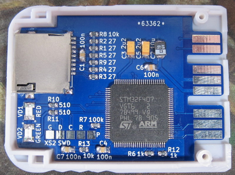
The first version of my memory card on STM32F407
It turned out quickly, reliably, but expensive. Can you do it cheaper? Well, well, the challenge is accepted. Considering the specifics of the task, I chose STM32F042F6. Here's what happened:
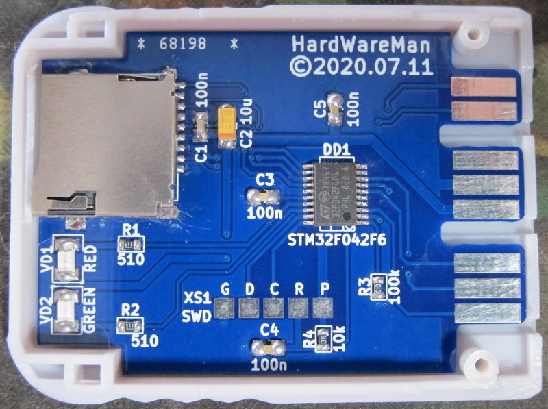
Second version of my memory card on STM32F042
We have a slave card, so frequency stabilization with an external quartz resonator is not needed, an internal oscillator is enough. This controller has one hardware SPI, so I gave it to the SD card to reduce transport delays. PSIO will be software here.
Software implementation
The first thing to do is work with an SD card in SPI mode. I will not dwell on this too much, it has long been chewed up and scattered across the Internet. The init, read and write code of the sector is given below.
Card_Init ()
//
TCardType Card_Init( void )
{	//
	TCardType Res;
	uint32_t Cnt,OCR;
	uint8_t Dat, Resp;
	//
	CARD_OFF; Res = ctNone;
	//  SPI    PCLK/128: 48/128 = 0,375
	SPI1->CR1 &= ~SPI_CR1_SPE;
	SPI1->CR1 = SPI_CR1_MSTR | SPI_LOW_SPEED;
	SPI1->CR1 |= SPI_CR1_SPE;
	//
	HAL_Delay( 1 );
	//   256
	for (Cnt = 0;Cnt < 256;Cnt++ )
	{	//
		Card_SPI( 0xFF );
	}
	//
	CARD_ON;
	//
	do
	{	//  0xFF
		Dat = Card_SPI( 0xFF );
	} while ( Dat != 0xFF );
	// CMD0: GO_IDLE_STATE
	Card_SendCMD( &CARD_CMD0[ 0 ], CMD_LENGTH ); Resp = Card_WaitResp( &OCR, DISABLE, 128 );
	//   ?
	if ( Resp == 0x01 )
	{	//    IDLE_STATE,  CMD8: SEND_IF_COND
		Card_SendCMD( &CARD_CMD8[ 0 ], CMD_LENGTH ); Resp = Card_WaitResp( &OCR, ENABLE, 128 );
		//
		if ( Resp != 0x01 )
		{	//   SDv1/MMC
			do
			{	//  ACMD41: APP_SEND_OP_COND
				Card_SendCMD( &CARD_ACMD41[ 0 ], CMD_LENGTH ); Resp = Card_WaitResp( &OCR, ENABLE, 128 );
			} while ( Resp == 0x01 );
			//   ?
			if ( Resp == 0x00 )
			{	//   SD v1
				Res = ctSD1;
			}
			else
			{	//   MMC,
				Res = ctUnknown;
			}
		}
		else
		{	//   SDv2
			if ( (OCR & 0x0001FF) == 0x0001AA )
			{	//   SDv2
				do
				{	//  ACMD55: APP_CMD
					Card_SendCMD( &CARD_CMD55[ 0 ], CMD_LENGTH ); Resp = Card_WaitResp( &OCR, DISABLE, 128 );
					//
					if ( Resp == 0x01 )
					{	//  ACMD41: APP_SEND_OP_COND
						Card_SendCMD( &CARD_ACMD41[ 0 ], CMD_LENGTH ); Resp = Card_WaitResp( &OCR, ENABLE, 128 );
					}
				} while ( Resp == 0x01 );
				//   ?
				if ( Resp == 0x00 )
				{	//  CMD58: READ_OCR
					Card_SendCMD( &CARD_CMD58[ 0 ], CMD_LENGTH ); Resp = Card_WaitResp( &OCR, ENABLE, 128 );
					//  ?
					if ( Resp == 0x00 )
					{	//  OCR
						if ( (OCR & 0x40000000) == 0x00000000 )
						{	//
							Res = ctSD2;
						}
						else
						{	//
							Res = ctSD3;
						}
					}
					else
					{	//
						Res = ctUnknown;
					}
				}
				else
				{	//
					Res = ctUnknown;
				}
			}
			else
			{	//
				Res = ctUnknown;
			}
		}
	}
	else
	{	//
		if ( Res != 0xFF ) { Res = ctUnknown; }
	}
	//
	if ( (Res == ctSD1) || (Res == ctSD2) )
	{	//    512
		// CMD16: SET_BLOCKLEN
		Card_SendCMD( &CARD_CMD16[ 0 ], CMD_LENGTH ); Resp = Card_WaitResp( &OCR, DISABLE, 128 );
		//  ?
		if ( Resp != 0x00 )
		{	//
			Res = ctUnknown;
		}
	}
	//
	while ( (SPI1->SR & SPI_SR_BSY) != 0x0000 ) { }
	CARD_OFF;
	//
	if ( (Res != ctNone) && (Res != ctUnknown) )
	{	//  SPI    PCLK/2: 48/2 = 24
		SPI1->CR1 &= ~SPI_CR1_SPE;
		SPI1->CR1 = SPI_CR1_MSTR;
		SPI1->CR1 |= SPI_CR1_SPE;
	}
	//
	return Res;
}
Card_Read ()
//      DMA
FunctionalState Card_Read( TCardType CardType, uint8_t *Buf, uint32_t *Loaded, uint32_t Addr )
{	//
	FunctionalState Res;
	uint8_t Cmd[ 6 ];
	uint8_t Dat,Resp;
	uint32_t Cnt;
	//
	Res = DISABLE;
	// ,      ?
	if ( *(Loaded) != Addr )
	{	//
		*(Loaded) = Addr;
		//
		if ( (CardType == ctSD1) || (CardType == ctSD2) )
		{	//      LBA
			Addr *= 0x00000200;
		}
		//
		while ( 1 )
		{	//     -
			if ( CardType == ctNone ) { break; }
			if ( CardType == ctUnknown ) { break; }
			//
			Cmd[ 0 ] = CARD_CMD17;
			Cmd[ 1 ] = Addr >> 24;
			Cmd[ 2 ] = Addr >> 16;
			Cmd[ 3 ] = Addr >> 8;
			Cmd[ 4 ] = Addr;
			Cmd[ 5 ] = 0xFF;
			//
			CARD_ON;
			//
			do
			{	//  0xFF
				Dat = Card_SPI( 0xFF );
			} while ( Dat != 0xFF );
			//
			Card_SendCMD( &Cmd[ 0 ], CMD_LENGTH ); Resp = Card_WaitResp( (uint32_t *)&Cmd[ 0 ], DISABLE, 128 );
			//
			if ( Resp != 0x00 ) { break; }
			//
			Cnt = 2048;
			do
			{	//
				Dat = Card_SPI( 0xFF );
				//
				Cnt--;
			} while ( (Dat == 0xFF) && (Cnt > 0) );
			// ?
			if ( Cnt == 0 ) { break; }
			//   ?
			if ( Dat != CARD_DATA_TOKEN ) { break; }
			//  ,
			for (Cnt = 0;Cnt < 512;Cnt++)
			{	//
				*(Buf) = Card_SPI( 0xFF ); Buf++;
			}
			//  CRC
			Cmd[ 0 ] = Card_SPI( 0xFF );
			Cmd[ 1 ] = Card_SPI( 0xFF );
			//
			Res = ENABLE;
			//
			break;
		}
	}
	else
	{	//
		Res = ENABLE;
	}
	//
	while ( (SPI1->SR & SPI_SR_BSY) != 0x0000 ) { }
	CARD_OFF;
	//   ,
	if ( Res == DISABLE ) { *(Loaded) = 0xFFFFFFFF; }
	//
	return Res;
}
Card_Write ()
//      DMA
FunctionalState Card_Write( TCardType CardType, uint8_t *Buf, uint32_t *Loaded, uint32_t Addr )
{	//
	FunctionalState Res;
	uint8_t Cmd[ 6 ];
	uint8_t Dat,Resp;
	uint32_t Cnt;
	//
	Res = DISABLE;
	//
	if ( (CardType == ctSD1) || (CardType == ctSD2) )
	{	//      LBA
		Addr *= 0x00000200;
	}
	//
	while ( 1 )
	{	//     -
		if ( CardType == ctNone ) { break; }
		if ( CardType == ctUnknown ) { break; }
		//
		Cmd[ 0 ] = CARD_CMD24;
		Cmd[ 1 ] = Addr >> 24;
		Cmd[ 2 ] = Addr >> 16;
		Cmd[ 3 ] = Addr >> 8;
		Cmd[ 4 ] = Addr;
		Cmd[ 5 ] = 0xFF;
		//
		CARD_ON;
		//
		do
		{	//  0xFF
			Dat = Card_SPI( 0xFF );
		} while ( Dat != 0xFF );
		//
		Card_SendCMD( &Cmd[ 0 ], CMD_LENGTH ); Resp = Card_WaitResp( (uint32_t *)&Cmd[ 0 ], DISABLE, 128 );
		//
		if ( Resp != 0x00 ) { break; }
		//
		Card_SPI( CARD_DATA_TOKEN );
		//
		//  ,
		for (Cnt = 0;Cnt < 512;Cnt++)
		{	//
			Card_SPI( *(Buf) ); Buf++;
		}
		//  CRC
		Card_SPI( 0xFF );
		Card_SPI( 0xFF );
		//
		Res = ENABLE;
		//
		break;
	}
	//
	while ( (SPI1->SR & SPI_SR_BSY) != 0x0000 ) { }
	CARD_OFF;
	// ?
	if ( Res == ENABLE )
	{	//
		*(Loaded) = Addr;
	}
	else
	{	//
		*(Loaded) = 0xFFFFFFFF;
	}
	//
	return Res;
}
The card initializes at 375kHz (PCLK / 128) and operates at 24MHz (PCLK / 2). At such speeds, measurements showed that SDv1 and SDHC give a sector within 2.8ms for the entire transaction. This should be remembered because important for PSIO read operation.
Now let's look at PSIO. As mentioned above, we have it in software anyway. There are only two signals to track: SEL and CLK . The first one we will track on both fronts and make preparations for the exchange of data:
EXTI2_3_IRQHandler ()
//    SEL
void EXTI2_3_IRQHandler( void )
{	//
	EXTI->PR = 0x00000004;
	//   SEL
	if ( MEM_SEL )
	{	// SEL = 1
		EXTI->IMR &= 0xFFFFFFFE;
		State.PSIO.Mode = mdSync;
		//
		LED_GREEN_OFF;
	}
	else
	{	// SEL = 0
		EXTI->IMR |= 0x00000001;
		State.PSIO.Bits = 7;
		//
		LED_GREEN_OFF; LED_RED_OFF;
	}
	//
	MEM_DAT1; MEM_nACK;
}
We will only catch the CLK signal along the front. The fact is that STM32F042 operates only at 48MHz and its performance is too small for our task. And if you make an interrupt on both fronts, then during the transfer of a byte, it practically does not get out of the interrupt handler and everything works right on the verge of possibility, sometimes failing. And if you react only to the front, and the work that needs to be done on the decline is done at the end of the interrupt, then everything is fine in less than 55% of the CLK period , because several checks can be thrown out. I am sure that if this handler is written in assembler as optimally as possible, then it would be able to work even on both jumps. Here is the handler code:
EXTI0_1_IRQHandler ()
//    CLK
void EXTI0_1_IRQHandler( void )
{	//
	EXTI->PR = 0x00000001;
	//
	uint16_t AckTime;
	//
	AckTime = 0;
	//
	State.PSIO.DataIn >>= 1;
	if ( MEM_CMD )
	{	//  1
		State.PSIO.DataIn |= 0x80;
	}
	else
	{	//  0
		State.PSIO.DataIn &= 0x7F;
	}
	//
	if ( State.PSIO.Bits > 0 )
	{	//
		State.PSIO.Bits--;
	}
	else
	{	//  ?
		if ( State.PSIO.Bits == 0 )
		{	//
			State.PSIO.Bits = 7;
			//
			State.PSIO.DataOut = State.PSIO.DataIn;
			//
			switch ( State.PSIO.Mode )
			{	//
				case mdSync : {	//
								if ( State.PSIO.DataIn == 0x81 )
								{	//
									State.PSIO.Mode = mdCmd;
									//
									State.PSIO.DataOut = State.MemCard.Status;
									//  ACK
									AckTime = AckNormal;
								}
								else
								if ( State.PSIO.DataIn == 0x01 )
								{	//   ,      .
									State.PSIO.Mode = mdDone;
								}
								//
								break;
							}
				//
				case mdCmd : {	//
								State.PSIO.Mode = mdParam;
								//
								State.MemCard.Cmd = State.PSIO.DataIn;
								State.MemCard.Bytes = 0;
								//
								State.PSIO.DataOut = 0x5A;
								//  ACK
								AckTime = AckNormal;
								//
								break;
							}
				//
				case mdParam : {	//     ACK
									AckTime = AckNormal;
									//
									switch ( State.MemCard.Cmd )
									{	//  : R
										case 0x52 : {	//
														switch ( State.MemCard.Bytes )
														{	//
															case 0 : { State.PSIO.DataOut = 0x5D; break; }
															case 1 : { break; }
															case 2 : { State.MemCard.Sector = State.PSIO.DataIn * 0x0100; State.MemCard.Check = State.PSIO.DataIn; break; }
															case 3 : { State.MemCard.Sector += State.PSIO.DataIn; State.MemCard.Check ^= State.PSIO.DataIn; State.PSIO.DataOut = 0x5C;
																	   State.SDCard.CardOp = coRead; AckTime = AckDelayed; break; }
															case 4 : { State.PSIO.DataOut = 0x5D; AckTime = AckDelayed; break; }
															case 5 : { State.PSIO.DataOut = State.MemCard.Sector >> 8; AckTime = AckDelayed; break; }
															case 6 : { State.PSIO.DataOut = State.MemCard.Sector; AckTime = AckDelayed;
																	   State.PSIO.Mode = mdRdData; State.MemCard.Bytes = 0; break; }
															default : { State.PSIO.Mode = mdDone; AckTime = 0; break; }
														}
														//
														LED_GREEN_ON;
														//
														break;
													}
										//  : W
										case 0x57 : {	//
														switch ( State.MemCard.Bytes )
														{	//
															case 0 : { State.PSIO.DataOut = 0x5D; break; }
															case 1 : { break; }
															case 2 : { State.MemCard.Sector = State.PSIO.DataIn * 0x0100; State.MemCard.Check = State.PSIO.DataIn; break; }
															case 3 : { State.MemCard.Sector += State.PSIO.DataIn; State.MemCard.Check ^= State.PSIO.DataIn; // break; }
																	   State.PSIO.Mode = mdWrData; State.MemCard.Bytes = 0; break; }
															default : { State.PSIO.Mode = mdDone; AckTime = 0; break; }
														}
														//
														LED_RED_ON;
														//
														break;
													}
										//  : S
										case 0x53 : {	//
														switch ( State.MemCard.Bytes )
														{	//
															case 0 : { State.PSIO.DataOut = 0x5D; break; }
															case 1 : { State.PSIO.DataOut = 0x5C; break; }
															case 2 : { State.PSIO.DataOut = 0x5D; break; }
															case 3 : { State.PSIO.DataOut = 0x04; break; }
															case 4 : { State.PSIO.DataOut = 0x00; break; }
															case 5 : { State.PSIO.DataOut = 0x00; break; }
															case 6 : { State.PSIO.DataOut = 0x80; break; }
															default : { State.PSIO.Mode = mdDone; AckTime = 0; break; }
														}
														//
														break;
													}
										//
										default : { State.PSIO.Mode = mdDone; break; }
									}
									//
									if ( State.PSIO.Mode == mdParam ) { State.MemCard.Bytes++; }
									//
									break;
								}
				//
				case mdRdData : {	//     ACK
									AckTime = AckNormal;
									//
									if ( State.MemCard.Bytes < 128 )
									{	//
										State.PSIO.DataOut = State.MemCard.Data[ State.MemCard.Bytes ]; State.MemCard.Check ^= State.PSIO.DataOut;
									}
									else
									{	//
										switch ( State.MemCard.Bytes )
										{	//
											case 128 : { State.PSIO.DataOut = State.MemCard.Check; break; }
											//
											case 129 : { State.PSIO.DataOut = 0x47; break; }
											//
											default : { State.PSIO.Mode = mdDone; AckTime = 0; LED_GREEN_OFF; break; }
										}
									}
									//
									State.MemCard.Bytes++;
									//
									break;
								}
				//
				case mdWrData : {	//     ACK
									AckTime = AckNormal;
									//
									if ( State.MemCard.Bytes < 128 )
									{	//
										State.MemCard.Data[ State.MemCard.Bytes ] = State.PSIO.DataIn; State.MemCard.Check ^= State.PSIO.DataIn;
									}
									else
									{	//
										switch ( State.MemCard.Bytes )
										{	//
											case 128 : {	//
															if ( State.MemCard.Check == State.PSIO.DataIn ) { State.MemCard.Check = 0x47; } else { State.MemCard.Check = 0x4E; }
															//
															State.PSIO.DataOut = 0x5C;
															//
															break;
														}
											//
											case 129 : { State.PSIO.DataOut = 0x5D; break; }
											//
											case 130 : {	//  ,
															if ( State.MemCard.Sector < 0x4000 )
															{	//  ,
																State.PSIO.DataOut = State.MemCard.Check;
																//   ?
																if ( State.MemCard.Check == 0x47 )
																{	//
																	State.SDCard.CardOp = coWrite;
																	//
																	State.MemCard.Status &= ~StateNew;
																}
															}
															else
															{	//  ,
																State.PSIO.DataOut = 0xFF;
															}
															//
															break;
														}
											//
											default : { State.PSIO.Mode = mdDone; AckTime = 0; break; }
										}
									}
									//
									State.MemCard.Bytes++;
									//
									break;
								}
				// ,
				case mdDone : { break; }
				//   -
				default : { State.PSIO.Mode = mdSync; break; }
			}
		}
	}
	//
	if ( State.PSIO.Mode != mdSync )
	{	//
		if ( State.PSIO.DataOut & 0x01 )
		{	//  1
			MEM_DAT1;
		}
		else
		{	//  0
			MEM_DAT0;
		}
		//
		State.PSIO.DataOut >>= 1;
	}
	//  ACK?
	if ( AckTime > 0 )
	{	//  CNT
		TIM3->CNT = AckTime;
		//
		State.PSIO.Ack = DISABLE;
		//
		TIM3->SR = 0x0000;
		//
		TIM3->CR1 |= TIM_CR1_CEN;
	}
}
The TIM3 timer will be responsible for generating the ACK . This is necessary in order for the kernel to be free to work with the SD card during this delay. The timer interrupt handler is like this:
TIM3_IRQHandler ()
//   TIM3
void TIM3_IRQHandler( void )
{	//
	TIM3->SR = 0x0000;
	//
	if ( State.PSIO.Ack == ENABLE )
	{	//   ACK
		MEM_nACK;
	}
	else
	{	//   ACK
		MEM_ACK;
		//
		State.PSIO.Ack = ENABLE;
		//
		TIM3->CNT = 0;
		//
		TIM3->CR1 |= TIM_CR1_CEN;
	}
}
The code is commented enough and I think it doesn't need much analysis. I will only note that after receiving the second byte of the sector number in the read command, we set the flag for the read operation from the SD card for the code that spins in the eternal loop of the main () function. And immediately after that, the next 4 ACKs are issued with an extended time. In the interface it looks like this:

Screenshot from the logic analyzer program, 4 large delays in the transaction are highlighted
In total, about 3.5ms is typed, and this is more than enough for the algorithm in the main code to read the sector. Moreover, this code can only work when there is no interruption, i.e. just in those big pauses. During recording, the flag is set at the very end and due to the fact that the system allows the memory card to complete the recording, the main code works without interference from interrupts. Now let's take a look at the code of the main loop.
main ()
	//
	while ( 1 )
	{	//
		if ( CARD_nCD == 0 )
		{	//
			if ( State.SDCard.CardType == ctNone )
			{	//
				LED_GREEN_ON; LED_RED_OFF;
				//    ,
				State.SDCard.CardType = Card_Init();
				//  ?
				if ( State.SDCard.CardType != ctUnknown )
				{	//
					if ( Card_FSInit( &State.SDCard, &CARD_IMAGE[ 0 ] ) == ENABLE )
					{	//   ,
						EXTI->IMR |= 0x00000004;
						//
						LED_GREEN_OFF; LED_RED_OFF;
					}
					else
					{	//
						State.SDCard.CardType = ctUnknown;
						//
						LED_GREEN_ON; LED_RED_ON;
					}
				}
				else
				{	//
					LED_GREEN_ON; LED_RED_ON;
				}
			}
		}
		else
		{	//
			if ( State.SDCard.CardType != ctNone )
			{	//  ,  PSIO
				EXTI->IMR &= 0xFFFFFFFA;
				//
				State.PSIO.Mode = mdSync; State.PSIO.Bits = 0; State.PSIO.DataIn = 0x00; State.PSIO.DataOut = 0; State.PSIO.Ack = DISABLE;
				State.MemCard.Status = StateNew;
				State.SDCard.CardType = ctNone; State.SDCard.CardOp = coIdle; State.SDCard.LoadedLBA = 0xFFFFFFFF;
			}
			//
			LED_GREEN_OFF; LED_RED_OFF;
		}
		//
		if ( (State.SDCard.CardType != ctNone) && (State.SDCard.CardType != ctUnknown) )
		{	//  ?
			if ( State.SDCard.CardOp == coWrite )
			{	//
				Ofs = State.MemCard.Sector & 0x03FF;
				LBA = (Ofs >> 2) & 0x000000FF;
				Ofs = (Ofs << 7) & 0x00000180;
				//
				Card_Read( State.SDCard.CardType, &State.SDCard.CardBuf[ 0 ], &State.SDCard.LoadedLBA, State.SDCard.CardList[ LBA ] );
				//
				for (Cnt = 0;Cnt < 128;Cnt++)
				{	//
					State.SDCard.CardBuf[ Ofs + Cnt ] = State.MemCard.Data[ Cnt ];
				}
				//
				Card_Write( State.SDCard.CardType, &State.SDCard.CardBuf[ 0 ], &State.SDCard.LoadedLBA, State.SDCard.CardList[ LBA ] );
				//
				LED_RED_OFF;
				//
				State.SDCard.CardOp = coIdle;
			}
			//  ?
			if ( State.SDCard.CardOp == coRead )
			{	//
				Ofs = State.MemCard.Sector & 0x03FF;
				LBA = (Ofs >> 2) & 0x000000FF;
				Ofs = (Ofs << 7) & 0x00000180;
				//
				Card_Read( State.SDCard.CardType, &State.SDCard.CardBuf[ 0 ], &State.SDCard.LoadedLBA, State.SDCard.CardList[ LBA ] );
				//
				for (Cnt = 0;Cnt < 128;Cnt++)
				{	//
					State.MemCard.Data[ Cnt ] = State.SDCard.CardBuf[ Ofs + Cnt ];
				}
				//
				State.SDCard.CardOp = coIdle;
			}
		}
	}
In an eternal loop, the SD card insertion signal is constantly analyzed. If you pull it out on the go, the code will disable the PSIO and the PS1 will "lose" the card. If the card is inserted back (or just power on with the card inserted), then at first there will be an attempt to initialize the card with the Card_Init () function, which will return the type of the detected card. This is important because SDv1 and other SDHC / SDXC addressing methods are different. The initialization code itself does not carry any secrets and was spied on in a heap of examples available on the Internet about FatFS and similar projects.
Following the initialization of the card, the tricky function Card_FSInit () is called. This is the main feature of this project. The fact is that STM32F042 is modest in capabilities and will not be able to pull full FatFS support at the required speed. Therefore, I came up with this method: the image file is always 128KiB, therefore, you only need to know 256 sectors of 512 bytes, each of which will have exactly 4 sectors of our PS1 memory card. Thus, we do the following:
- We analyze the sector LBA = # 0 for MBR. If this is indeed the MBR, then we get a new sector where the MBS is located.
- Having received the address of the supposed MBS (it can be # 0, if there is no MBR, or some number, if there is MBR), we start analyzing it for belonging to one of the FATs: FAT12, FAT16, FAT32 or vFAT.
- If the sector has passed the check, then we take information about the structure from it and look for an element with the file name in the root directory. In this case, it is 'MEMCRD00.BIN'.
- If such a file is found, then we check its size - it must be strictly fixed at 0x20000 bytes. If everything is so, we get the number of the first cluster.
- If we have reached this point, then we already have all the necessary information to build a list of physical LBA sectors where our image is located. Going through the FAT chain and using the structure information from the MBS, we fill in a table of 256 LBA sector numbers.
If successful, PSIO starts up and PS1 will see the card as its usual 15-block card. If an error occurs at any stage, the operation is interrupted, both LEDs light up and everything remains in this state until the power is removed or the SD card is replaced. Here is the code for this procedure:
Card_FSInit ()
//      ,    FAT16
FunctionalState Card_FSInit( TSDCard *SDCard, const uint8_t *FName )
{	//
	FunctionalState Res;
	uint8_t *Buf;
	uint8_t Pos;
	uint16_t ClustSize,Reserv,RootSize,FATSize,Cluster;
	uint32_t Cnt,LBA,SysOrg,FATOrg,RootOrg,DataOrg;
	int Compare;
	//
	Res = DISABLE; SysOrg = 0; Cluster = 0xFFFF;
	//
	while ( 1 )
	{	//   0
		if ( Card_Read( SDCard->CardType, &SDCard->CardBuf[ 0 ], &SDCard->LoadedLBA, SysOrg ) == DISABLE ) { break; }
		//   #0  MBR
		if ( *((uint16_t *)&SDCard->CardBuf[ 0x01FE ]) != 0xAA55 ) { break; }
		//    MBR
		if ( ((SDCard->CardBuf[ 0x01BE ] == 0x00) || (SDCard->CardBuf[ 0x01BE ] == 0x80)) &&
			 ((SDCard->CardBuf[ 0x01CE ] == 0x00) || (SDCard->CardBuf[ 0x01CE ] == 0x80)) &&
			 ((SDCard->CardBuf[ 0x01DE ] == 0x00) || (SDCard->CardBuf[ 0x01DE ] == 0x80)) &&
			 ((SDCard->CardBuf[ 0x01EE ] == 0x00) || (SDCard->CardBuf[ 0x01EE ] == 0x80)) )
		{	//   MBR,
			for (Cnt = 0;Cnt < 4;Cnt++)
			{	//
				if ( (SDCard->CardBuf[ (Cnt * 0x0010) + 0x01C2 ] == 0x01) ||	//  0x01: FAT12
					 (SDCard->CardBuf[ (Cnt * 0x0010) + 0x01C2 ] == 0x04) ||	//  0x04: FAT16
					 (SDCard->CardBuf[ (Cnt * 0x0010) + 0x01C2 ] == 0x06) ||	//  0x06: Big FAT16
					 (SDCard->CardBuf[ (Cnt * 0x0010) + 0x01C2 ] == 0x0E) )		//  0x0E: vFAT
				{	//  ,   MBS
					SysOrg = SDCard->CardBuf[ (Cnt * 0x0010) + 0x01C6 ];
					SysOrg += (SDCard->CardBuf[ (Cnt * 0x0010) + 0x01C7 ] * 0x00000100);
					SysOrg += (SDCard->CardBuf[ (Cnt * 0x0010) + 0x01C8 ] * 0x00010000);
					SysOrg += (SDCard->CardBuf[ (Cnt * 0x0010) + 0x01C9 ] * 0x01000000);
					//
					break;
				}
			}
		}
		//    MBS
		if ( Card_Read( SDCard->CardType, &SDCard->CardBuf[ 0 ], &SDCard->LoadedLBA, SysOrg ) == DISABLE ) { break; }
		//    MBS
		if ( *((uint16_t *)&SDCard->CardBuf[ 0x01FE ]) != 0xAA55 ) { break; }
		if ( SDCard->CardBuf[ 0x000D ] == 0x00 ) { break; }
		if ( (SDCard->CardBuf[ 0x0010 ] == 0x00) || (SDCard->CardBuf[ 0x0010 ] > 0x02) ) { break; }
		if ( SDCard->CardBuf[ 0x0015 ] != 0xF8 ) { break; }
		if ( *((uint32_t *)&SDCard->CardBuf[ 0x001C ]) != SysOrg ) { break; }
		if ( SDCard->CardBuf[ 0x0026 ] != 0x29 ) { break; }
		if ( *((uint16_t *)&SDCard->CardBuf[ 0x0036 ]) != 0x4146 ) { break; }
		if ( *((uint16_t *)&SDCard->CardBuf[ 0x0038 ]) != 0x3154 ) { break; }
		if ( SDCard->CardBuf[ 0x003A ] != 0x36 ) { break; }
		//   ,
		ClustSize = SDCard->CardBuf[ 0x000D ];
		Reserv = *((uint16_t *)&SDCard->CardBuf[ 0x000E ]);
		RootSize = (SDCard->CardBuf[ 0x0012 ] * 0x0100) + SDCard->CardBuf[ 0x0011 ];
		FATSize = *((uint16_t *)&SDCard->CardBuf[ 0x0016 ]);
		//   FAT  ROOT
		FATOrg = SysOrg + Reserv;
		RootOrg = FATOrg + (FATSize * 2);
		DataOrg = RootOrg + (RootSize / 16 );
		//   ,
		for (LBA = 0;LBA < (RootSize / 16);LBA++)
		{	//
			if ( Card_Read( SDCard->CardType, &SDCard->CardBuf[ 0 ], &SDCard->LoadedLBA, RootOrg + LBA ) == ENABLE )
			{	//  16 ,
				for (Cnt = 0;Cnt < 16;Cnt++)
				{	//
					Compare = memcmp( &SDCard->CardBuf[ Cnt * 32 ], &CARD_IMAGE[ 0 ], 11 );
					if (  Compare == 0 )
					{	//  ,
						if ( *((uint32_t *)&SDCard->CardBuf[ (Cnt * 32) + 0x001C ]) == 0x00020000 )
						{	//  ,
							Cluster = *((uint16_t *)&SDCard->CardBuf[ (Cnt * 32) + 0x001A ]);
							//
							Res = ENABLE;
							//
							break;
						}
					}
				}
				//    -
				if ( Res == ENABLE ) { break; }
			}
			else
			{	//   -
				break;
			}
		}
		//  ,  ,
		if ( Res == ENABLE )
		{	//     ,
			Pos = 0;
			do
			{	//
				if ( Cluster < 0x0002 )
				{	// ,
					Res = DISABLE; break;
				}
				//  LBA
				LBA = DataOrg + ((Cluster - 2) * ClustSize);
				//
				for (Cnt = 0;Cnt < ClustSize;Cnt++)
				{	//  LBA
					SDCard->CardList[ Pos ] = LBA + Cnt;
					//
					Pos++; if ( Pos == 0 ) { break; }
				}
				//    ,
				//       ,
				if ( Pos != 0 )
				{	//
					LBA = FATOrg; Reserv = Cluster;
					while ( Reserv > 256 ) { LBA++; Reserv -= 256; }
					//
					if ( Card_Read( SDCard->CardType, &SDCard->CardBuf[ 0 ], &SDCard->LoadedLBA, LBA ) == ENABLE )
					{	//
						Cluster = *((uint16_t *)&SDCard->CardBuf[ Reserv * 2 ]);
					}
					else
					{	//
						Res = DISABLE; break;
					}
				}
			} while ( (Cluster != 0xFFFF) && (Pos != 0) );
		}
		//
		break;
	}
	//
	return Res;
}
To be honest, since this is just PoC, only FAT16 search is implemented here. FAT12, probably, does not need to be supported - microSD of such small volumes does not exist. But FAT32 or vFAT can be added if someone needs it in the future.
The name of the image 'MEMCRD00.BIN' was not chosen by chance. The fact is that in the future I plan to add image selection via a standard combination of buttons on the joypad for multi-page memory cards: when SELECT is pressed, a single press on L1 / R1 follows. And by changing the last 2 characters, you can support 100 images in the root directory, from 'MEMCRD00.BIN' to 'MEMCRD99.BIN'. There is a groundwork for this in the SCK interrupt handler in the PSIO interface, the branch where the call to the joypad is analyzed. There is no problem to make a sniffer, but the PS1 controller peripherals are rich and you will have to support almost all of them.
As a result, the device turned out to be efficient and everyone can repeat it if he wants. The link to the whole project is here. I will be glad to help everyone interested in the comments to the article.
PS I would really like to indicate here a list of all the sources of information that I used in creating this project, but alas, this is very difficult. Much was overheard by chance. Something came in the form of TXT files with general information about the PS1 over 15 years ago, for those who wanted to write their own emulator. And now it all exists as a few text files on my hard drive. We can say that the entire Internet has been the source of information for the past 15 years.