Back in 2018, I came across the Pultoscope project, quite well-known in my circles . In short, this is an extremely primitive oscilloscope built on the arduino 328 series. Given its simplicity, I repeated it in a few hours on a breadboard and then I got carried away ... But first things first.
So. The repeated device turned out to be so necessary and convenient that the idea itself arose to supplement it with the basic functions of a multimeter, including a meter for capacitance of capacitors and inductance of coils. As a result, I began to work on creating the ideal "for myself" device. Having empirically estimated the functionality that I use in one way or another in the design of my devices, I excluded the functions I did not need and determined the mandatory ones. First of all, I proceeded from the fact that for the most part I do not use voltages over 24 volts and currents over 3 amperes. Usually these are low-voltage equipment, IoT, ESP32, arduino and similar devices in ideology. Accordingly, when measuring resistances, capacitances and inductances, it is not so much accuracy that is important as understanding the rating and, preferably,automatic detection of color and code marking. Usually, the measurement of these parameters is required when designing the power supply circuits of devices. At least a minimal check for the presence of data on the UART port is required, and ideally reading them. Here I began to think about the form factor of the device.
Actually a list of what I ended up with:
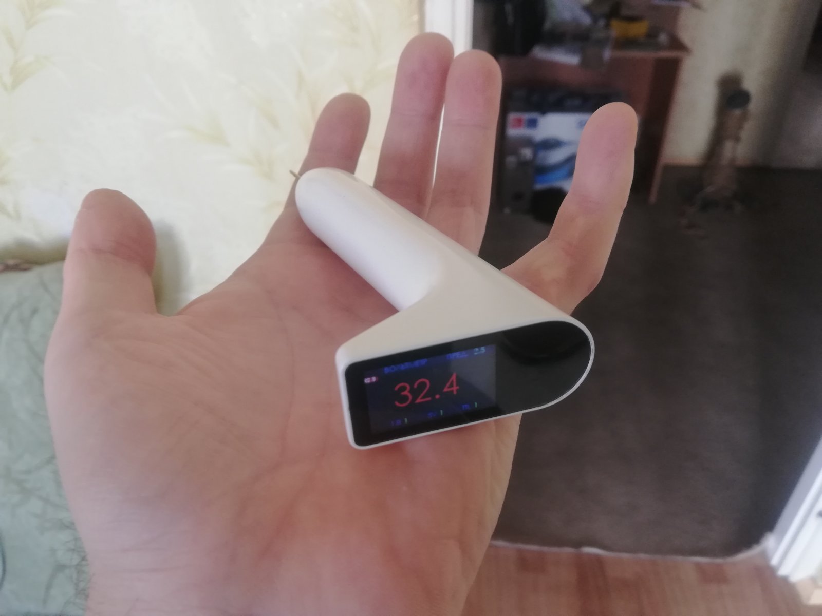
Voltmeter with a measurement accuracy of no more than 0.01 volts. Usually even tenths are sufficient. In this case, it is imperative to display the values of logic levels for CMOS1.8, TTL and CMOS5.0 volts.
Ammeter up to 3 amperes with the ability to display a graph of changes in values.
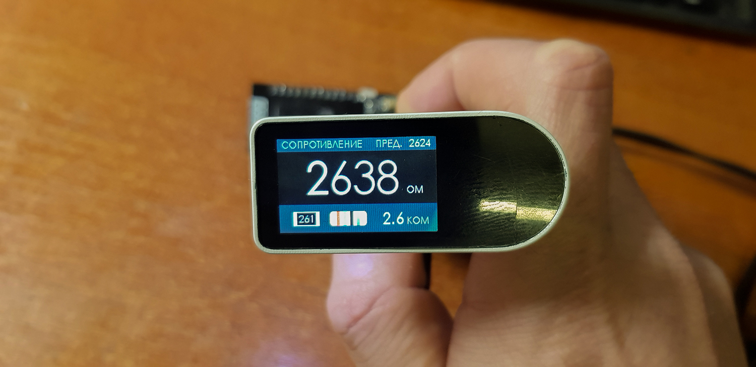
Measurement of denominations of passive elements. One of the most important things for me was the ability to display color and SMD markings of parts on the fly. The same is true when measuring inductance and capacitance, except for the color coding. Automatic range selection, of course.
. , /. 100. .
UART .
. , . . . .
. , , :
, , , , .
, .
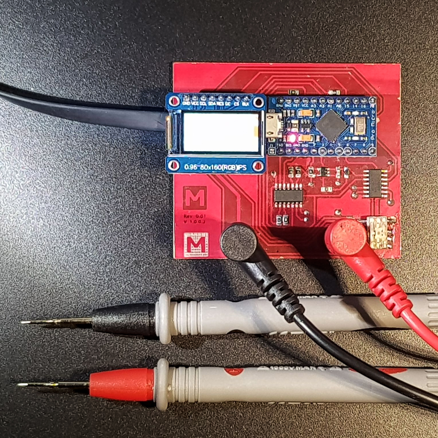
- , . , , . :

. , "" - .
, . ATMEGA32U4. - USB . arduino . arduino, . ACS712. , .
, :
, .
:

JDY-08. , . , . :
.
, "", - . , ESP32, . , 0,96 80x160, 1,14 135*240 .
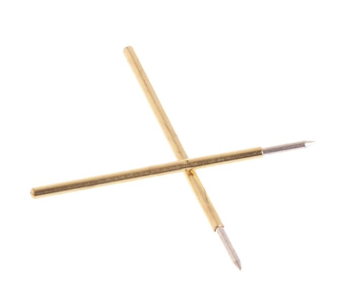
, , 3 , . 3- 3D . , , . ESP32 , . ttp223. - , . . , 3 . , bluetooth WiFi , . , , . , , , , , . , .
, , ACS712, INA219. - I2, - 26 . , , . , 100 AD5245. . . TYPE-C .
JLCPCB , . . :

:
, . , . . App Inventor.
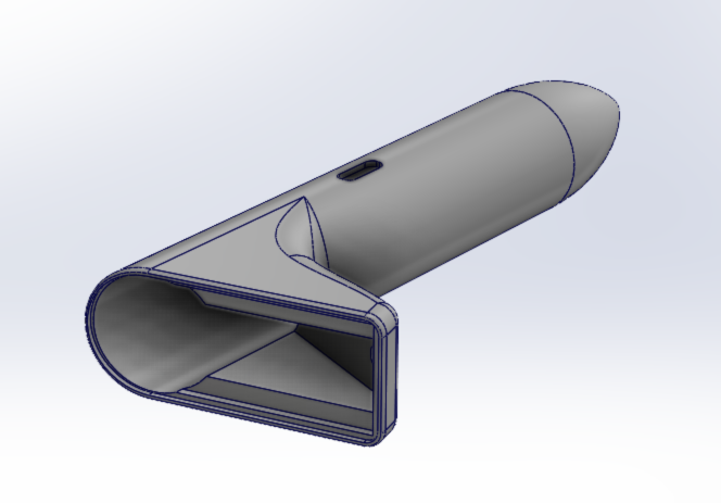
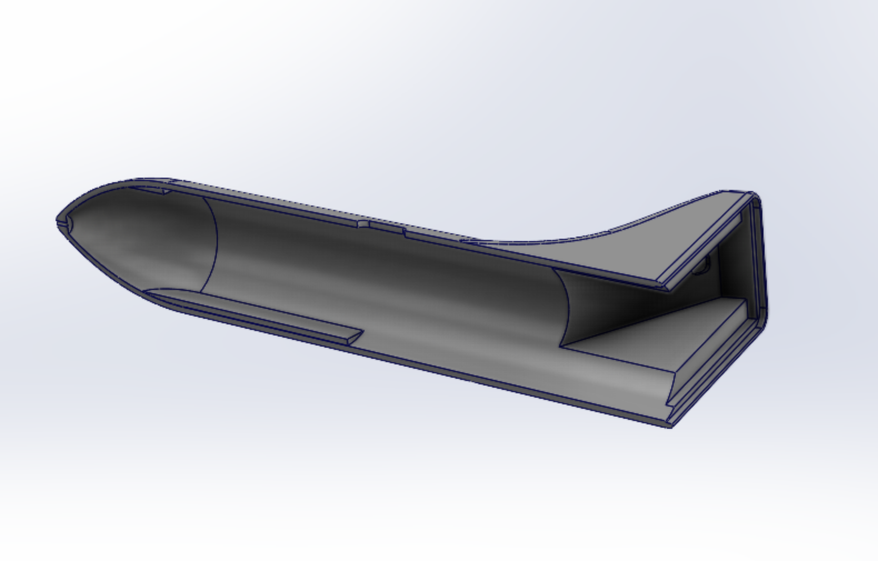
Today, I have written the basic software basis. I had to tinker with the body, but I was able to reduce the cost of the mold as much as possible. To understand the order of prices, the cost of the matrix is $ 5600, the resource is 300k of castings. The cost of 1 casting, including a cover for the display and illumination of the working area $ 1.53. Dimensions ~ 120x22mm. Solid ABS body with SoftTouch coating.
But even that is quite expensive for me. maybe I will try to turn to crowdfunding. If the topic is interesting, I am ready to post articles periodically.