An even lower level (avr-vusb)
USB on registers: STM32L1 / STM32F1
USB on registers: bulk endpoint using the example of Mass Storage
USB on registers: isochronous endpoint using the example of Audio device We
continue to deal with USB on STM32L151 controllers. As in the previous part, there will be nothing platform-dependent here, but it will be USB-dependent. More specifically, we will consider the third type of endpoint - interrupt. And we will do this using the example of a composite device "keyboard + tablet" ( link to the source ).
Just in case, I warn you: this article (like everyone else) is rather a synopsis of what I understood while understanding this topic. Many things have remained "magic" and I will be grateful if there is a specialist who can explain them.
First of all, let me remind you that the HID (Human Interface Device) protocol is not intended for exchanging large amounts of data. The entire exchange is based on two concepts: an event and a state . An event is a one-time message that occurs in response to an external or internal impact. For example, the user pressed a button or moved the mouse. Or on one keyboard I disabled NumLock, after which the host is forced and the second one to send the appropriate command to
Thus, the purpose of an interrupt point is the same as an interrupt in a controller - to quickly report a rare event. But USB is a host-centric thing, so the device has no right to start the transfer on its own. To get around this, the USB developers came up with a crutch: the host periodically sends requests to read all interrupt points. The frequency of the request is configured by the last parameter in the EndpointDescriptor (this is part of the ConfigurationDescriptor). We have already seen the bInterval field in the previous chapters, but its value was ignored. Now he has finally found a use. The value has a size of 1 byte and is set in milliseconds, so we will be polled at intervals from 1 ms to 2.55 seconds. For low speed devices, the minimum interval is 10ms. The presence of a crutch with interrupt points polling for us meansthat even in the absence of exchange, they will be wasting bus bandwidth.
The logical conclusion: interrupt points are only for IN transactions. In particular, they are used to transmit events from the keyboard or mouse, to notify about changes in the service lines of the COM port, to synchronize the audio stream and the like. But for all this, you will have to add other types of points. Therefore, in order not to complicate the example, we will restrict ourselves to the implementation of the HID device. In fact, we already made such a device in the first part, but there additional points were not used at all, and the structure of the HID protocol was not considered.
ConfigurationDescriptor
static const uint8_t USB_ConfigDescriptor[] = {
ARRLEN34(
ARRLEN1(
bLENGTH, // bLength: Configuration Descriptor size
USB_DESCR_CONFIG, //bDescriptorType: Configuration
wTOTALLENGTH, //wTotalLength
1, // bNumInterfaces
1, // bConfigurationValue: Configuration value
0, // iConfiguration: Index of string descriptor describing the configuration
0x80, // bmAttributes: bus powered
0x32, // MaxPower 100 mA
)
ARRLEN1(
bLENGTH, //bLength
USB_DESCR_INTERFACE, //bDescriptorType
0, //bInterfaceNumber
0, // bAlternateSetting
2, // bNumEndpoints
HIDCLASS_HID, // bInterfaceClass:
HIDSUBCLASS_BOOT, // bInterfaceSubClass:
HIDPROTOCOL_KEYBOARD, // bInterfaceProtocol:
0x00, // iInterface
)
ARRLEN1(
bLENGTH, //bLength
USB_DESCR_HID, //bDescriptorType
USB_U16(0x0110), //bcdHID
0, //bCountryCode
1, //bNumDescriptors
USB_DESCR_HID_REPORT, //bDescriptorType
USB_U16( sizeof(USB_HIDDescriptor) ), //wDescriptorLength
)
ARRLEN1(
bLENGTH, //bLength
USB_DESCR_ENDPOINT, //bDescriptorType
INTR_NUM, //bEdnpointAddress
USB_ENDP_INTR, //bmAttributes
USB_U16( INTR_SIZE ), //MaxPacketSize
10, //bInterval
)
ARRLEN1(
bLENGTH, //bLength
USB_DESCR_ENDPOINT, //bDescriptorType
INTR_NUM | 0x80, //bEdnpointAddress
USB_ENDP_INTR, //bmAttributes
USB_U16( INTR_SIZE ), //MaxPacketSize
10, //bInterval
)
)
};
The attentive reader may immediately notice the descriptions of the endpoints. With the second, everything is in order - IN point (since the addition with 0x80 has been made) of interrupt type, size and interval are specified. But the first one seems to be declared as OUT, but at the same time interrupt, which contradicts what was said earlier. And common sense too: the host does not need crutches to transfer anything to the device at any time. But in this way, other rakes are bypassed: the type of endpoint in STM32 is set not for one point, but only for the IN / OUT pair, so it will not work to set the 0x81st point to the interrupt type, but to the 0x01st control. However, this is not a problem for the host, it would probably send the same data in the bulk point too ... which, however, I will not check.
HID descriptor
The structure of the HID descriptor is most similar to the configuration file "name = value", but unlike it, "name" is a numeric constant from the USB-specific list, and "value" is either also a constant or a variable of size 0 up to 3 bytes.
Important:for some "names" the length of the "value" is specified in the 2 least significant bits of the "name" field. For example, let's take LOGICAL_MINIMUM (the minimum value that this variable can take in normal mode). The code for this constant is 0x14. Accordingly, if there is no "value" (it seems that this does not happen, but I will not argue - for some reason this case was entered), then the descriptor will contain a single number 0x14. If the "value" is 1 (one byte), then 0x15, 0x01 will be written. For a two-byte value 0x1234, 0x16, 0x34, 0x12 will be written - the value is written from low to high. Well, before the heap, the number 0x123456 will be 0x17, 0x56, 0x34, 0x12.
Naturally, I am too lazy to memorize all these numerical constants, so we will use macros. Unfortunately, I never found a way to get them to figure out the size of the passed value themselves and expand into 1, 2, 3, or 4 bytes. Therefore, I had to make a crutch: a macro without a suffix is responsible for the most common 8-bit values, with a suffix 16 for 16-bit values, and with 24 for 24-bit values. Macros have also been written for "composite" values like the range LOGICAL_MINMAX24 (min, max), which expand into 4, 6, or 8 bytes.
As with configuration files, there are “sections” called pages (usage_page) that group devices by purpose. For example, there is a page with basic peripherals such as keyboards, mice and just buttons, there are joysticks and gamepads (I sincerely recommend looking at which ones! There are also for tanks, and for spaceships, and for submarines and for anything else), there are even displays ... True, where to look for software that can work with all this, I have no idea.
Within each page, a specific device is selected. For example, for a mouse it is a pointer and buttons, and for a tablet - a stylus or a user's finger (what ?!). They also designate the component parts of the device. So, part of the pointer is its X and Y coordinates. Some characteristics can be grouped into a "collection", but why I do not really understand why this is done. In the documentation, fields are sometimes marked with a couple of letters about the purpose of the field and how to work with it:
| CA | Collection (application) | Service information, not corresponding to any variable |
| CL | Collection (logical) | - / - |
| CP | Collection (phisical) | - / - |
| Dv | Dynamic Value | input or output value (variable) |
| MC | Momentary control | status flag (1-flag cocked, 0-cleared) |
| OSC | One shot control | one-time event. Only transition 0-> 1 is processed |
There are others, of course, but they are not used in my example. If, for example, the X field is marked as DV, then it is considered a variable of non-zero length and will be included in the report structure. The MC or OSC fields are also included in the report, but are 1 bit in size.
One report (data packet sent or received by the device) contains the values of all the variables described in it. The description of the button speaks of only one occupied bit, but for relative coordinates (how much the mouse has moved, for example), at least a byte is required, and for absolute coordinates (like for a touchscreen), at least 2 bytes are needed. Plus, many controls have their own physical limitations. For example, an ADC of the same touchscreen can have a resolution of only 10 bits, that is, give values from 0 to 1023, which the host will have to scale to full screen resolution. Therefore, in addition to the purpose of each field, the descriptor also specifies the range of its permissible values (LOGICAL_MINMAX), plus sometimes the range of physical values (in millimatres there, or in degrees) and the presentation in the report is mandatory.The representation is set by two numbers: the size of one variable (in bits) and their number. For example, the coordinates of touching the touchscreen in the device we are creating are set as follows:
USAGE( USAGE_X ), // 0x09, 0x30,
USAGE( USAGE_Y ), // 0x09, 0x31,
LOGICAL_MINMAX16( 0, 10000 ), //0x16, 0x00, 0x00, 0x26, 0x10, 0x27,
REPORT_FMT( 16, 2 ), // 0x75, 0x10, 0x95, 0x02,
INPUT_HID( HID_VAR | HID_ABS | HID_DATA), // 0x91, 0x02,
Here you can see that two variables are declared, varying in the range from 0 to 10000 and occupying two sections of 16 bits in the report.
The last field says that the above variables will be read by the host (IN) and explains exactly how. I will not describe its flags in detail, I will dwell on only a few. The HID_ABS flag indicates that the value is absolute, that is, no history affects it. The alternative value HID_REL indicates that the value is an offset from the previous one. The HID_VAR flag says that each field is responsible for its own variable. The alternative value HID_ARR says that not the states of all buttons from the list will be transmitted, but only the numbers of the active ones. This flag applies only to single-bit fields. Instead of transmitting 101/102 states of all keyboard buttons, you can limit yourself to a few bytes with a list of pressed keys. Then the first parameter REPORT_FMT will be responsible for the size of the number, and the second for the number.
Since the size of all variables is set in bits, it is logical to ask: what about the buttons, because their number may not be a multiple of 8, and this will lead to alignment difficulties when reading and writing. It would be possible to allocate a byte to each button, but then the volume of the report would greatly increase, which is unpleasant for high-speed programs like interrupt. Instead, the buttons are tried to be placed closer to each other, and the remaining space is filled with bits with the HID_CONST flag.
Now we can, if not write a descriptor from scratch, then at least try to read it, that is, determine which bits this or that field corresponds to. It is enough to count the INPUT_HIDs and the corresponding REPORT_FMTs. Just keep in mind that I came up with such macros, no one else uses them. In other people's descriptors, you will have to look for input, report_size, report_count, or even numeric constants.
Now you can bring the entire descriptor:
static const uint8_t USB_HIDDescriptor[] = {
//keyboard
USAGE_PAGE( USAGEPAGE_GENERIC ),//0x05, 0x01,
USAGE( USAGE_KEYBOARD ), // 0x09, 0x06,
COLLECTION( COLL_APPLICATION, // 0xA1, 0x01,
REPORT_ID( 1 ), // 0x85, 0x01,
USAGE_PAGE( USAGEPAGE_KEYBOARD ), // 0x05, 0x07,
USAGE_MINMAX(224, 231), //0x19, 0xE0, 0x29, 0xE7,
LOGICAL_MINMAX(0, 1), //0x15, 0x00, 0x25, 0x01,
REPORT_FMT(1, 8), //0x75, 0x01, 0x95, 0x08
INPUT_HID( HID_DATA | HID_VAR | HID_ABS ), // 0x81, 0x02,
//reserved
REPORT_FMT(8, 1), // 0x75, 0x08, 0x95, 0x01,
INPUT_HID(HID_CONST), // 0x81, 0x01,
REPORT_FMT(1, 5), // 0x75, 0x01, 0x95, 0x05,
USAGE_PAGE( USAGEPAGE_LEDS ), // 0x05, 0x08,
USAGE_MINMAX(1, 5), //0x19, 0x01, 0x29, 0x05,
OUTPUT_HID( HID_DATA | HID_VAR | HID_ABS ), // 0x91, 0x02,
// 1
REPORT_FMT(3, 1), // 0x75, 0x03, 0x95, 0x01,
OUTPUT_HID( HID_CONST ), // 0x91, 0x01,
REPORT_FMT(8, 6), // 0x75, 0x08, 0x95, 0x06,
LOGICAL_MINMAX(0, 101), // 0x15, 0x00, 0x25, 0x65,
USAGE_PAGE( USAGEPAGE_KEYBOARD ), // 0x05, 0x07,
USAGE_MINMAX(0, 101), // 0x19, 0x00, 0x29, 0x65,
INPUT_HID( HID_DATA | HID_ARR ), // 0x81, 0x00,
)
//touchscreen
USAGE_PAGE( USAGEPAGE_DIGITIZER ), // 0x05, 0x0D,
USAGE( USAGE_PEN ), // 0x09, 0x02,
COLLECTION( COLL_APPLICATION, // 0xA1, 0x0x01,
REPORT_ID( 2 ), //0x85, 0x02,
USAGE( USAGE_FINGER ), // 0x09, 0x22,
COLLECTION( COLL_PHISICAL, // 0xA1, 0x00,
USAGE( USAGE_TOUCH ), // 0x09, 0x42,
USAGE( USAGE_IN_RANGE ), // 0x09, 0x32,
LOGICAL_MINMAX( 0, 1), // 0x15, 0x00, 0x25, 0x01,
REPORT_FMT( 1, 2 ), // 0x75, 0x01, 0x95, 0x02,
INPUT_HID( HID_VAR | HID_DATA | HID_ABS ), // 0x91, 0x02,
REPORT_FMT( 1, 6 ), // 0x75, 0x01, 0x95, 0x06,
INPUT_HID( HID_CONST ), // 0x81, 0x01,
USAGE_PAGE( USAGEPAGE_GENERIC ), //0x05, 0x01,
USAGE( USAGE_POINTER ), // 0x09, 0x01,
COLLECTION( COLL_PHISICAL, // 0xA1, 0x00,
USAGE( USAGE_X ), // 0x09, 0x30,
USAGE( USAGE_Y ), // 0x09, 0x31,
LOGICAL_MINMAX16( 0, 10000 ), //0x16, 0x00, 0x00, 0x26, 0x10, 0x27,
REPORT_FMT( 16, 2 ), // 0x75, 0x10, 0x95, 0x02,
INPUT_HID( HID_VAR | HID_ABS | HID_DATA), // 0x91, 0x02,
)
)
)
};
In addition to the previously discussed fields, there is also such an interesting field as REPORT_ID. Since, as is clear from the comments, our device is composite, the host needs to somehow determine whose data it receives. For this, this field is needed.
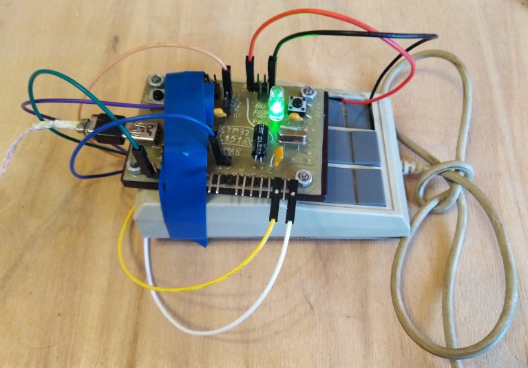
And one more field that I would like to draw your attention to is OUTPUT_HID. As the name implies, it is not responsible for receiving a report (IN), but for transmitting (OUT). It is located in the keyboard section and describes the CapsLock, NumLock, ScrollLock indicators as well as two exotic ones - Compose (a flag for entering some characters that do not have their own buttons like á, µ or) and Kana (entering hieroglyphs). Actually, for the sake of this field, we started the OUT point. In its handler, we will check if the CapsLock and NumLock indicators need to be lit: there are just two diodes on the board and are wired.
There is a third field related to data exchange - FEATURE_HID, we used it in the first example. If INPUT and OUTPUT are intended to transmit events, then FEATURE is a state that can be both read and written. True, this is done not through dedicated endpoints, but through the usual ep0 by means of appropriate requests.
If you look closely at the descriptor, you can restore the structure of the report. More precisely, two reports:
struct{
uint8_t report_id; //1
union{
uint8_t modifiers;
struct{
uint8_t lctrl:1; //left control
uint8_t lshift:1;//left shift
uint8_t lalt:1; //left alt
uint8_t lgui:1; //left gui. hyper, winkey
uint8_t rctrl:1; //right control
uint8_t rshift:1;//right shift
uint8_t ralt:1; //right alt
uint8_t rgui:1; //right gui
};
};
uint8_t reserved; //
uint8_t keys[6]; //
}__attribute__((packed)) report_kbd;
struct{
uint8_t report_id; //2
union{
uint8_t buttons;
struct{
uint8_t touch:1; //
uint8_t inrange:1; //
uint8_t reserved:6;// 1
};
};
uint16_t x;
uint16_t y;
}__attribute__((packed)) report_tablet;
We will send them by pressing the buttons on the board, moreover. since we are writing only an example of implementation, and not a finished device, we will do it in a barbaric way - by sending two reports, in the first of which "pressing" the keys, and in the second - "releasing". Moreover, with a huge "stupid" delay between the messages. If you do not send a report with the "released" keys, the system will consider that the key is still pressed and will repeat it. Naturally, there is no question of any efficiency, safety too, but it will do for the test. Oh yeah, where without another rake! The size of the structure must match what is described in the descriptor, otherwise Windows will pretend that it does not understand what they want from it. As usual, Linux ignores such errors and works as if nothing had happened.
During testing, I came across a funny side effect: in Windows7, when you click on the "touchscreen", the handwriting window pops up. I did not know about this feature.
If you have a finished device
... and I want to look at it from the inside. First of all, of course, we look, you can even from an ordinary user, ConfigurationDescriptor:
lsusb -v -d <VID:PID>
For the HID descriptor, I did not find (and did not look for) a better way than from root:
cat /sys/kernel/debug/hid/<address>/rdes
For the sake of completeness, it would be worth adding here how to look at similar things in other operating systems. But I have no relevant knowledge, maybe they will tell me in the comments. It is desirable, of course, without installing third-party software.
Conclusion
This is, in fact, all that I dug up on HID. The minimum plan - to learn how to read ready-made descriptors, emulate several devices at the same time and implement tablet input - is complete. Well, the philosophy of interrupt points was considered at the same time.
As in the bad time, I left a little documentation in the repository in case the USB-IF designers decide to ruin the site again.