In the early days, routers were ordinary computers with Network Interface Cards (NICs) attached to the bus.
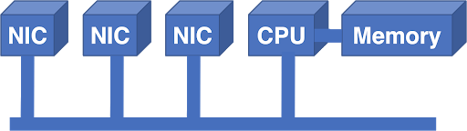
Figure 1 - Network interface cards connected to the bus.
Until a certain point, such a system worked. In this architecture, packets entered the NIC and were transferred from the NIC to memory by the CPU. The CPU made the forwarding decision and output the packet to the external NIC. CPU and memory are centralized resources with limited device support. The bus was also an additional limitation: the bus bandwidth had to support the bandwidth of all NICs at the same time.
If it is necessary to scale up the network, problems begin to arise very quickly. You can buy a faster processor, but how do you increase the bus power? If you double the bus speed, you need to double the bus interface speed on each NIC and CPU. This increases the cost of all boards, even if the capacity of a single NIC does not increase.
Lesson one: the cost of a router should grow linearly with its capabilities
Despite the lesson learned, a convenient solution for upscaling was to add another bus and processor:

Figure 2 - The solution to the problem of scaling the system was to add a new bus and processor.
The Arithmetic Logic Unit (ALU) was a Digital Signal Processing (DSP) chip chosen for its superior price-performance ratio. The additional bus increased the bandwidth, but the architecture did not grow in scale anyway. In other words, more ALUs and buses could not have been added to increase productivity.
Since ALUs were still a significant limitation, the next step was to add a Field Programmable Gate Array (FPGA) to the architecture to reduce the Longest Prefix Match (LPM) lookup load.

Figure 3 - The next step was to add the Field Programmable Gate Array.
Although this helped, it did not completely solve the problem. ALU was still overwhelmed. LPMs made up the bulk of the load, but the centralized architecture still didn't scale well, even if we got rid of some of the problem.
Lesson two: LPM can be implemented in silicon and are not a barrier to performance
Despite this lesson, the next step was taken in a different direction: towards replacing ALU and FPGA with a standard processor. The designers tried to scale up by adding more CPUs and more buses. It took a lot of effort for even a small increase in power, and the system still suffered from the bandwidth limitations of the centralized bus.
At this stage in the evolution of the Internet, more serious forces came into play. As the web became popular with the general public, the potential of the Internet began to become more evident. Telcos acquired regional NSFnet networks and began building commercial complexes. Application-Specific Integrated Circuits (ASICs) have become proven technologies, allowing more functionality to be implemented directly in silicon. The demand for routers has skyrocketed, and the need for significant scalability improvements has finally defeated engineering conservatism. To meet this demand, many startups have sprung up with a wide range of possible solutions.
The scheduled crossbar became one of the alternatives:

Figure 4 - Scheduled crossbar.
In this architecture, each NIC had an input and an output. The NIC processor made the forwarding decision, selected the output NIC, and sent a scheduling request to the switch (crossbar). The scheduler received all requests from the NICs, worked out the optimal solution, programmed the solution into the switch, and directed the inputs for transmission.
The problem with this scheme was that each output could "listen" to one input at a time, and the Internet traffic pulsed. If two packets needed to hit the same exit, one of them had to wait. Waiting for one packet caused other packets to wait on the same input, after which the system began to suffer from Head Of Line Blocking (HOLB), resulting in very poor router performance.
Lesson three: the internal structure of the router should not block signals even under load conditions
The migration to specialized chips also motivated designers to migrate to internal cell-based structures, since switching small, fixed-size cells is much easier than dealing with variable-length packets, sometimes large. However, the use of the switching cells also meant that the scheduler would have to run at a higher frequency, making scheduling much more difficult.
Another innovative approach was to build the NIC into a torus:

Figure 5 - Torus-shaped NIC.
In such a scheme, each NIC had connections to four neighbors, and the input NIC had to calculate a path through the structure to reach the output line card. This system had problems - the bandwidth was not the same. The transmission width in the north-south direction was higher than in the east-west direction. If the inbound traffic pattern was to move east-west, congestion would occur.
Lesson four: the internal structure of the router must have an even distribution of bandwidth, because we cannot predict the distribution of traffic.
A completely different approach was to create a complete NIC-NIC communications network and distribute cells across all NICs:
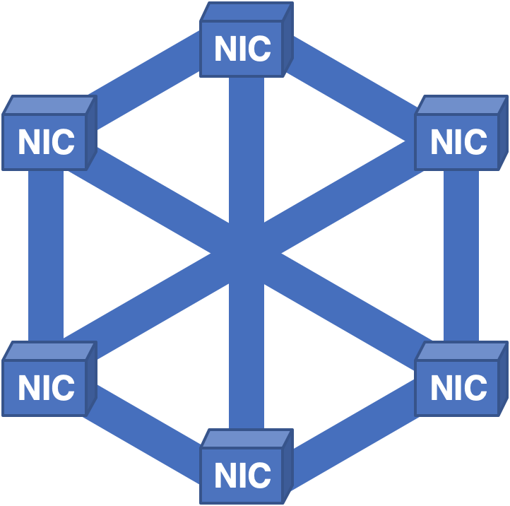
Figure 6 - Fully connected structure with distribution of cells to all NICs.
Despite learning the previous lessons, new problems were identified. In this architecture, everything worked well enough until it was necessary to remove the board for repair. Because each NIC contained cells for all of the packets in the system, when the card was removed, none of the packets could be recreated, resulting in short but painful downtime.
Lesson Five: Routers Don't Have a Single Point of Failure
We even took this architecture and turned it upside down:
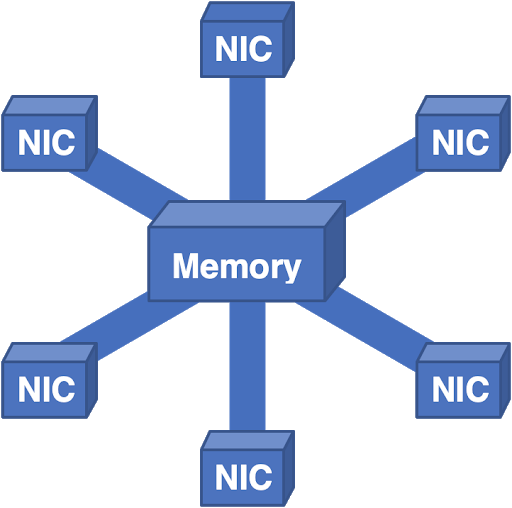
Figure 7 - Here all packets go to the central memory and then to the egress NIC.
This system worked pretty well, but memory scaling became a problem. You can just add a few controllers and memory banks, but at some point the overall bandwidth becomes too complex for physical design. Faced with practical physical constraints, we were forced to think in other directions.
The telephone network has become a source of inspiration for us. Long ago, Charles Close realized that scalable switches could be made by building networks of smaller switches. As it turned out, all the wonderful properties we need are present in the Clos network:

Figure 8 - Clos network.
Close network properties:
- Power grows with scale.
- Has no single point of failure.
- Maintains sufficient redundancy for fault tolerance.
- Copes with overloads by distributing the load throughout the structure.
We always implement inputs and outputs together, so we usually fold this image along the dotted line. This results in a folded Clos network, and this is what we use today in multi-case routers: some cases have a NIC and a layer of switches, in others - additional layers of switches.

Figure 9 - Collapsed Clos network.
Unfortunately, even this architecture has its own problems. The format of the cells used between switches is proprietary and owned by the chip manufacturer, which leads to dependency on chipsets. Dependence on a chip vendor is not much better than dependence on a single router vendor, the problems are the same: tying pricing and availability of devices to a single source. Hardware upgrades are challenging because the new cell switch must simultaneously support legacy connections and cell formats to maintain interoperability, as well as all link rates and cell formats of new equipment.
Each cell must be addressed to indicate the egress NIC to which it must transmit information. Such addressing is finite, which creates a scalability limit. Control and management in multi-case routers is still completely proprietary, causing another single vendor problem in the software stack.
Fortunately, we can solve these problems by changing our architecture philosophy. For the past fifty years, we have strived to scale routers. We have learned from the experience of building large clouds that the scale-out philosophy is often more successful.
The scale-out architecture uses a divide and conquer strategy rather than creating a huge, extremely fast single server. A rack of small servers can do the same job while being more reliable, flexible and cost effective.
This approach is also applicable to routers. Is it possible to take multiple small routers and line them up in a Clos topology to achieve similar architectural benefits while avoiding mesh-related issues? As it turned out, this is not particularly difficult:

Figure 10 - Replacing cell switches with packet switches, preserving the Clos topology for easier scaling.
By replacing the cell switches with packet switches and maintaining the Clos topology, we provide ease of scalability.
Scaling is possible in two dimensions: either adding new ingress routers and packet switches in parallel with existing layers, or adding additional switch layers. Since individual routers are fairly standardized today, we avoid dependence on a single vendor. All links use standard Ethernet, so there are no compatibility issues.
Upgrades are straightforward and straightforward: if the switch needs more channels, you can simply replace it with a larger switch. If you need to upgrade a separate channel and both ends of the channel have this capability, then you just need to upgrade the optics. Differing transmission rates of dissimilar links within a fabric are not a problem because each router acts as a rate mapper.
This architecture is already popular in the world of data centers and, depending on the number of switch layers, is called leaf-spine or super-spine architecture. It has proven to be highly reliable, stable and flexible.
From a transmission plane point of view, it is clear that this is a viable alternative to architecture. Problems remain with the control plane and the control plane. Scaling out the control plane requires an order of magnitude improvement in the scale of our control protocols. We are trying to implement it by improving the abstraction mechanisms by creating a proxy representation of the architecture that describes the entire topology as a single node.
Likewise, we are working to develop control plane abstractions that will allow us to control the entire Clos structure as a single router. This work is done as an open standard, so none of the technologies involved are proprietary.
Over the course of fifty years, router architectures have evolved leaps and bounds, and many mistakes have been made in the process of finding trade-offs between different technologies. Obviously, our evolution is not yet complete. In each iteration, we tackled the problems of the previous generation and discovered new challenges.
Hopefully, by carefully studying our past and current experience, we can move forward towards a more flexible and reliable architecture and create future improvements without completely replacing hardware.