
The second part is completely devoted to the description of the software used on the robot.
Since the developed robot (pi-tank) is largely designed for novice robot builders, everything will be simplified as much as possible, and at the end of the article an image for the raspberry pi will be attached for further independent study.
A small disclaimer. On the proposed image for raspberry pi, designed for an 8 GB sd card, everything is configured and installed. No further steps are required. This is done in order to simplify and facilitate the software part, since, based on practice, not every robotics technician makes it to the finish line when a multicomponent project is being implemented.
Therefore, the article is rather devoted to customizing the software "for yourself", but it will also shed light on how to assemble and configure everything from scratch.
The foundation
RPi-Cam-Web-Interface was taken as a starting point for development . Quite ancient, but nevertheless, has not lost its relevance "framework".
How to install it is described in detail on the project page and the complexities of calling:
shouldn't
git clone https://github.com/silvanmelchior/RPi_Cam_Web_Interface.git
cd RPi_Cam_Web_Interface
./install.sh
There are nuances for the buster distribution (it is written about them on the project website), but for Raspbian Stretch, which is used on the robot, everything is standard.
After installation, a web server is available, which displays the "default" picture at the address raspberry-ip : 8080 / html /:

This picture differs from what can be observed on the robot:

As it is not difficult to see, the robot page has arrows to control the camera gimbal (pan-tilt), based on the sg-90 servo, as well as custom buttons for controlling the robot ("headlights", "headlights off", etc.).
The purpose of the interface buttons is intuitive.
Also on the web page there are tabs for more detailed configuration of camera parameters, as well as work with the system:
How to get on raspberry
When loaded, raspberry becomes available via VNC with login credentials - pi, password - raspberry.
the wi-fi network to which it is connected by default - login - boss, password - 1234554321.
You can also access via ssh, the login-password pair is the same.
How everything works and where to change for yourself
All the filling is located in the / var / www / html / directory, and the RPi-Cam-Web-Interface itself starts from / home / pi / RPi-Cam_Web_Interface.
The camera gimbal is controlled by the blue arrows on the web page. The framework itself does not know how to manage servers out of the box. Therefore, an additional package is used
servoblaster
github.com/richardghirst/PiBits/tree/master/ServoBlaster
And there is a small nuance here. By default servoblaster uses gpio4 and gpio17 - raspberry pins to control gimbals (servo signal wires). By a lucky coincidence, the same pins are used by the raspberry pi "cap" - witty pi 3 mini, which is responsible for power supply, power-on schedules, etc. Therefore, so that the hardware does not interfere with each other, the pins for the serv were transferred for the purposes of the servoblaster.
This is done in /etc/rc.local with the command:
sudo /home/pi/PiBits/ServoBlaster/user/servod --p1pins=13,15,0,0,0,0,0,0 &
At the same time, 13.15 are physical pins, not gpio! The rest of the zeros are the ability to connect more servos and control them. That is, 6 more servos can be connected by designating pins instead of zeros.
* What pins are currently used by the servoblaster, you can look in the file - / dev / servoblaster-cfg
Also in /etc/rc.local raspberry pins are set to control the motors:
the code
gpio -g mode 5 out


     gpio -g mode 6 out


     gpio -g mode 9 out


     gpio -g mode 10 out


     gpio -g mode 11 out


     gpio -g mode 22 out


     gpio -g mode 27 out
* In this case, gpio22 and gpio27 are pins 13,15 that the servoblaster uses.
How to set up pan-tilt from scratch is described on the project page here .
How buttons are added is also described on the site in the "User buttons" section. To add or change buttons ("lights", etc.), you need to refer to the file / var / www / html /
userbuttons
,light.sh
-,lightoff.sh
,forward.sh
,reverse.sh
,left.sh
,right.sh
,stop.sh
,left-m.sh
,right-m.sh
,forward-m.sh
,reverse-m.sh
-,lightoff.sh
,forward.sh
,reverse.sh
,left.sh
,right.sh
,stop.sh
,left-m.sh
,right-m.sh
,forward-m.sh
,reverse-m.sh
Here, the lines mean the names of the buttons, as well as the corresponding control script.
The control scripts themselves are located in / var / www / html / macros. And, quite possibly, these scripts will have to be edited, tk. when connecting the wires to the l298n motor driver, the polarity may be different and the robot will go in the wrong direction, according to the pressed button.
To fix this, you need to open a script, for example /var/www/html/macros/left.sh And try combinations of replacing 1 and 0 with gpio. But as a rule, you can just change left.sh to forward.sh or to right.sh, etc. depending on the situation. The interface buttons with the "m" prefix are responsible for the so-called "low speed":
#!/bin/bash


     gpio -g write 9 0


     gpio -g write 11 1


     gpio -g write 6 0


     gpio -g write 5 1

This is implemented in scripts left-m.sh, etc. Previously used pwm for management. However, it became clear that with wi-fi delays and other circumstances, the distance that is realized when you press the button with pwm differs. The robot then goes too far until the moment when the "stop" is pressed, then practically does not react, especially when the batteries are discharging.
Therefore, a simple approach was implemented in the script - giving a signal and then, after a pause, suppressing it:
left-m.sh
#!/bin/bash


     gpio -g write 9 0


     gpio -g write 11 1


     gpio -g write 6 0


     gpio -g write 5 1


     sleep 0.3


     gpio -g write 9 0


     gpio -g write 11 0


     gpio -g write 6 0


     gpio -g write 5 0
Witty pi 3 mini and power management
The Witty pi 3 mini was purchased to minimize power loss when operating from the powerbank and to increase the overall operating time of the robot.
Previously, when the robot was turned off, which was implemented on the web page

, it was impossible to turn on the robot again without assistance. There were options using an external arduino, but all this was not easy and not aesthetically pleasing.
The Witty pi 3 mini is not the only solution of its kind, and not even the first in its line. But it is more or less affordable and works out of the box.
The software is installed extremely
simply
wget
www.uugear.com/repo/WittyPi3/install.sh
sudo sh install.sh
sudo sh install.sh
After installation, a clarifying setting may be required in /home/pi/uwi/uwi.conf
current settings
host='192.168.1.105';


     port=8000;


     web_socket_url='ws://'+host+':'+port+'/';


     response_timeout=5000;


     reconnect_timeout=1000;


     debug=0;


     wittypi3='/home/pi/wittypi';


     zero2go='/home/pi/zero2go';
Further, at each boot on the raspberry: 8000 (127.0.0.1:8000) web page, the
web interface with the settings will be available :

The first tab is just another way to control the gpio raspberry pi - the

second tab is directly the witty pi settings -
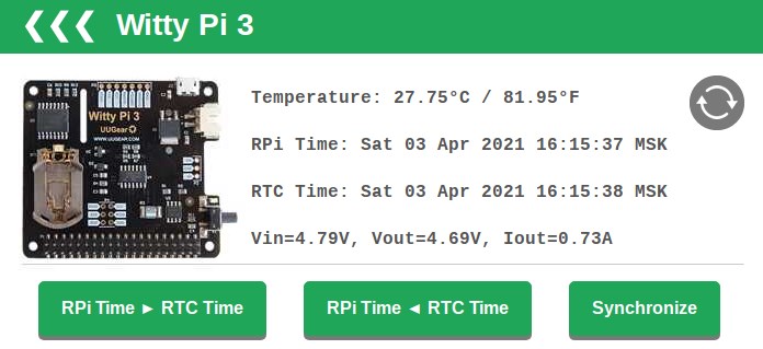
To the temperature sensor you can ignore it, because its accuracy is questionable.
You can configure it directly from the web page, but you can also use the script:
/home/pi/wittypi/wittyPi.sh. When the script is run, it outputs the same as available on the web page: Here you need:
>>> Current temperature: 28.75°C / 83.75°F


     >>> Your system time is: Sat 03 Apr 2021 16:20:47 MSK


     >>> Your RTC time is: Sat 03 Apr 2021 16:20:48 MSK


     >>> Vin=4.73V, Vout=4.68V, Iout=1.13A


     Now you can:


     1. Write system time to RTC


     2. Write RTC time to system


     3. Synchronize time


     4. Schedule next shutdown


     5. Schedule next startup


     6. Choose schedule script


     7. Set low voltage threshold


     8. Set recovery voltage threshold


     9. View/change other settings...


     10. Reset data...


     11. Exit
- synchronize the time on witty pi with the raspberry system clock (3. Synchronize time)
- write this time to rtc (1.Write system time to RTC)
- , -
-
6. Choose schedule script[1] 7:00_on_7:30_off_21:00_on_21:30_off.wpi
[2] on_10m_every_2h.wpi
[3] on_1h_every_2d.wpi
[4] on_30m_everyday_but_weekend.wpi
[5] on_5m_every_20m.wpi
[6] turn_on_every_hour.wpi
[5], 5 20 .
After selecting the script, the corresponding sleep intervals will be immediately indicated:

- be sure to look into other settings (9. View / change other settings ...)
Here you need to configure [5] Dummy load duration [0] - these are parasitic impulses for the powerbank that do not give it fall asleep. Since most powerbanks remove power at a minimized load. The range of values is 0-255.
All other settings can be left untouched.
Witty pi also assumes the ability to monitor the supply voltage and correct shutdown in case of a fall, as well as turn on under changed conditions.
More flexible adjustment is also available in terms of creating your own on and off schedules - script generator:
This is described in detail in the instructions .
Sleep pi-tanka
youtu.be/ZMiYcjzt534
That's all for now. If something is forgotten or incomprehensible - write.
Image for raspberry pi - download .