An even lower level (avr-vusb)
USB on registers: bulk endpoint using the example of Mass Storage
USB on registers: interrupt endpoint using the example of HID
USB on registers: isochronous endpoint using the example of Audio device
We have already met software USB using the example of AVR, it's time take on heavier stones - stm32. Our experimental subjects will be the classic STM32F103C8T6 as well as a representative of the low-power STM32L151RCT6 series. As before, we will not use purchased debug boards and HAL, preferring a bicycle.
Since there are two controllers in the title, it's worth talking about the main differences. First of all, this is a pull-up resistor telling the usb host that something has been stuck into it. In L151 it is built-in and controlled by the SYSCFG_PMC_USB_PU bit, but in F103 it is not, you will have to solder it to the board from the outside and connect it either to VCC or to the controller leg. In my case, the PA10 leg came under the arm. On which UART1 hangs ... And the other pin of UART1 conflicts with the button ... I threw a wonderful board, don't you think? The second difference is the amount of flash memory: in the F103 its 64 kB, and in the L151 as much as 256 kB, which we will use someday when studying Bulk endpoints. They also have slightly different clocking settings, and they can hang on different legs with light bulbs with buttons, but these are already quite trifles. Example for F103is available in the repository, so it will not be difficult to adapt the rest of the experiments with the L151 for it. Source codes are available here: github.com/COKPOWEHEU/usb
General principle of working with USB
Operation with USB in this controller is assumed using a hardware module. That is, we tell him what to do, he does and at the end pulls the “I'm ready!” Interrupt. Accordingly, we do not need to call almost anything from the main main (although I have provided the usb_class_poll function just in case). The normal cycle of work is limited to a single event - the exchange of data. The rest - reset, sleep and others - are exceptional, one-time events.
This time I will not go into the low-level details of the exchange. Anyone interested can read about vusb. But let me remind you that the exchange of ordinary data is not by one byte, but by packet, and the direction of transmission is set by the host. And he also dictates the names of these directions: IN transmission means that the host receives data (and the device transmits), and OUT means that the host transmits data (and we receive). Moreover, each packet has its own address - the number of the endpoint with which the host wants to communicate. For now, we will have a single endpoint 0, responsible for the device as a whole (for brevity, I will also call it ep0). What the rest are for, I will tell you in other articles. According to the standard, the size of ep0 is strictly 8 bytes for low-speed devices (to which the same vusb belongs) and a choice of 8, 16, 32,64 bytes for full speed ones like ours.
What if the data is too small and does not fill the buffer completely? Everything is simple here: in addition to the data in the packet, their size is also transmitted (this can be the wLength field or a low-level combination of SE0 signals, indicating the end of the transmission), so even if we need to transfer three bytes through ep0 of 64 bytes, then exactly three bytes will be transferred ... As a result, we will not waste bandwidth by driving unnecessary zeros. So do not be too small: if we can afford to spend 64 bytes, we spend without hesitation. Among other things, this will somewhat reduce the bus load, because it is easier to transfer a piece of 64 bytes (plus all headers and tails) at a time than 8 times 8 bytes each (to each of which, again, headers and tails).
And if there is too much data on the contrary? It's more complicated here. The data has to be split by the size of the endpoint and transferred in chunks. Let's say the size of ep0 is 8 bytes, and the host is trying to transmit 20 bytes. At the first interrupt, bytes 0-7 will come to us, in the second 8-15, in the third 16-20. That is, to collect the whole package, you need to receive as many as three interrupts. For this, in the same HAL, a tricky buffer was invented, with which I tried to figure it out, but after the fourth level of transferring the same thing between functions, I spat. As a result, in my implementation, buffering falls on the shoulders of the programmer.
But the host at least always says how much data it is trying to transfer. When we transfer data, we must somehow trick the low-level states of the legs to make it clear that the data is over. More precisely, to make it clear to the usb module that the data is over and that you need to pull the legs. This is done in an obvious way - by writing only part of the buffer. For example, if we have 8 bytes in the buffer, and we have written 4, then obviously we have only 4 bytes of data, after which the module will send the magic combination SE0 and everyone will be happy. And if we wrote 8 bytes, does it mean that we have only 8 bytes, or that this is only a part of the data that fit into the buffer? The usb module thinks that the. Therefore, if we want to stop the transfer, then after writing the 8-byte buffer, we must write the next 0-byte one. This is called ZLP, Zero Length Packet. How it looks in the code,I'll tell you a little later.
Organization of memory
According to the standard, the size of endpoint 0 can be up to 64 bytes. Any other size - as much as 1024 bytes. The number of points can also differ from device to device. The same STM32L1 support up to 7 points at the input and 7 at the output (not counting ep0), that is, up to 14 kB of buffers alone. Which in such a volume most likely will never be needed by anyone. Unacceptable consumption of memory! Instead, the usb module chews off a chunk of shared kernel memory and uses it. This area is called PMA (packet memory area) and starts with USB_PMAADDR. And to indicate where the buffers of each endpoint are located inside it, an array of 8 elements each with the following structure is allocated at the beginning, and only then the actual area for data:
typedef struct{
volatile uint32_t usb_tx_addr;
volatile uint32_t usb_tx_count;
volatile uint32_t usb_rx_addr;
volatile union{
uint32_t usb_rx_count;
struct{
uint32_t rx_count:10;
uint32_t rx_num_blocks:5;
uint32_t rx_blocksize:1;
};
};
}usb_epdata_t;
Here you set the beginning of the transmit buffer, its size, then the beginning of the receive buffer and its size. Note firstly that usb_tx_count does not set the actual buffer size, but the amount of data to transfer. That is, our code must write data to the address usb_tx_addr, then write their size to usb_tx_count and only then pull the usb module register that the data is written, transfer it. Pay even more attention to the strange format of the receive buffer size: it is a structure in which 10 rx_count bits are responsible for the real amount of data read, while the rest are really for the buffer size. It is necessary to know the piece of iron to where you can write, and where other people's data begins. The format of this setting is also quite interesting: the rx_block_size flag tells in what units the size is set. If it is reset to 0,then in 2-byte words, then the buffer size is 2 * rx_num_blocks, that is, from 0 to 62. And if set to 1, then in 32-byte blocks, respectively, the buffer size then turns out to be 32 * rx_num_blocks and lies in the range from 32 to 512 (yes, not up to 1024, such is the limitation of the controller).
To place buffers in this area, we will use a semi-dynamic approach. That is, allocate memory on demand, but not free it (malloc / free was not enough to invent yet!). The beginning of the unallocated space will be pointed to by the variable lastaddr, which initially points to the beginning of the PMA minus the table of structures discussed above. Well, each time the function to configure the next endpoint usb_ep_init () is called, it will be shifted by the buffer size specified there. And the desired value will be entered into the corresponding cell of the table, of course. The value of this variable is reset upon a reset event, followed by a call to usb_class_init (), in which the points are reconfigured in accordance with the user's task.
Working with transmit-receive registers
As it was just said, at reception we read how much data was actually received (the usb_rx_count field), then we read the data itself, then we pull the usb module so that the buffer is free, you can receive the next packet. For transmission, the other way around: we write the data to the buffer, then we set how much has been written to usb_tx_count and finally pull the module that the buffer is full, we can transfer it.
The first rakebegin when working with the buffer itself: it is not organized in 32 bits, like the rest of the controller, and not in 8 bits, as you might expect. And 16 bits each! As a result, it is written and read in 2 bytes, aligned with 4 bytes. Thank you ST for doing such a perversion! How boring life would be without it! Now ordinary memcpy is indispensable, you have to fence special functions. By the way, if anyone loves DMA, then it seems to be able to do such a transformation on its own, although I have not tested it.
And then the second rakewith writing to the registers of the module. The fact is that for the configuration of each endpoint - for its type (control, bulk, etc.) and state - one register USB_EPnR is responsible, that is, you just can't change a bit in it, you need to watch out so as not to spoil the rest. And secondly, there are already four types of bits in this register! Some are available only for reading (this is great), others for reading and writing (also normal), others ignore record 0, but when writing 1, they change the state to the opposite (fun begins), and the fourth, on the contrary, ignore record 1, but record 0 resets them to 0. Tell me, what addict thought of making bits in one register that ignore 0 and ignore 1 ?! No, I'm ready to assume that this was done for the sake of preserving the integrity of the register, when it is accessed from both code and hardware. But what do you want,Was it too lazy to put the inverter so that the bits were reset by writing 1? Or else an inverter so that other bits are inverted by writing 0? As a result, setting two register bits looks like this (thanks again to ST for such a perversion):
#define ENDP_STAT_RX(num, stat) do{USB_EPx(num) = ((USB_EPx(num) & ~(USB_EP_DTOG_RX | USB_EP_DTOG_TX | USB_EPTX_STAT)) | USB_EP_CTR_RX | USB_EP_CTR_TX) ^ stat; }while(0)
Oh yes, I almost forgot: they don't have access to the register by number either. That is, macros USB_EP0R, USB_EP1R, etc. they have, but if the number came in a variable, then alas. I had to invent my own USB_EPx () - and what to do.
Well, to comply with the formalities, I will point out that the readiness flag (that is, that we have already read the previous data) is set by the USB_EP_RX_VALID bit mask, and for recording (that is, we have written the data in full and can be transferred) - by the USB_EP_TX_VALID mask.
Processing IN and OUT requests
The occurrence of a USB interrupt can signal different things, but for now we will focus on communication requests. The flag for such an event will be the USB_ISTR_CTR bit. If we saw it, we can figure out which point the host wants to communicate with. The point number is hidden under the USB_ISTR_EP_ID bit mask, and the IN or OUT direction is hidden under the USB_EP_CTR_TX and USB_EP_CTR_RX bits, respectively.
Since we can have many points, and each with its own processing algorithm, we will create callback functions for all of them, which would be called upon the corresponding events. For example, the host sent data to endpoint3, we read USB-> ISTR, pulled from there that the request is OUT and that the point number is 3. So we call epfunc_out [3] (3). The point number in brackets is transmitted if suddenly the user code wants to hang one handler on several points. Oh yes, even in the USB standard, it is customary to mark IN input points with a cocked 7th bit. That is, endpoint3 at the output will have the number 0x03, and at the input - 0x83. Moreover, these are different points, they can be used simultaneously, they do not interfere with each other. Well, almost: in stm32 they have a setting of the type (bulk, interrupt, ...) for both reception and transmission. So the same 0x83th IN point will match callback 'at epfunc_in [3] (3 | 0x80).
The same principle applies for ep0. The only difference is that its processing takes place inside the library, and not inside the user code. But what if you need to process specific requests like some HID - don't bother picking the library code? For this, there are special callbacks usb_class_ep0_out and usb_class_ep0_in, which are called in special places and have a special format, which I will talk about closer to the end.
It is worth mentioning another not very obvious point related to the occurrence of packet processing interruptions. With OUT requests, everything is simple: the data came, here they are. But the IN interrupt is generated not when the host has sent an IN request, but when the transmit buffer is empty. That is, in principle, this interrupt is similar to the UART buffer underrun interrupt. Therefore, when we want to transfer something to the host, we simply write the data into the transfer buffer, wait for the IN interrupt and add what does not fit (do not forget about the ZLP). And okay, even with the "usual" endpoints, they are controlled by the programmer, you can ignore them for now. But through ep0, the exchange is always going on. Therefore, work with it should be built into the library.
As a consequence, the beginning of the transfer is carried out by the ep0_send function, which writes the address of the beginning of the buffer and the amount of data to be transferred to the global variable, after which, note, it itself pulls the IN event handler for the first time. In the future, this handler will be called on hardware events, but you still need to give a push.
Well, the handler itself is quite simple: it writes the next piece of data to the transfer buffer, shifts the address of the beginning of the buffer and reduces the number of bytes remaining for transfer. A separate crutch is associated with the same ZLP and the need to respond to some requests with an empty packet. In this case, the end of the transfer is indicated by the fact that the data address has become NULL. And an empty packet - that it is equal to the ZLPP constant. Both occur when the size is equal to zero, so no actual recording occurs.
A similar algorithm will have to be implemented when working with other endpoints. But this is the user's concern. And the logic of their work is often different from working with ep0, so in some cases this option will be more convenient than buffering at the library level.
USB communication logic
The host determines the very fact of connection by the presence of a pull-up resistor between any data line and the power supply. He resets the device, assigns it an address on the bus and tries to determine what exactly was stuck into it. To do this, it reads device and configuration descriptors (and, if necessary, specific ones). He can also read the string descriptors to understand what the device calls itself (although if the pair VID: PID is familiar to him, he would prefer to pull the lines from his database). After that, the host can load the appropriate driver and work with the device in a language it understands. The language it understands includes specific requests and calls to specific interfaces and endpoints. We'll get to that too, but first we need the device to be at least displayed in the system.
Processing SETUP requests: DeviceDescriptor
A person who has tinkered at USB at least a little should have been wary for a long time: COKPOWEHEU, you are talking about IN and OUT requests, but SETUP is also spelled out in the standard. Yes, it is, but it is rather a kind of OUT request, specially structured and intended exclusively for endpoint 0. Let's talk about its structure and features of work.
The structure itself looks like this:
typedef struct{
uint8_t bmRequestType;
uint8_t bRequest;
uint16_t wValue;
uint16_t wIndex;
uint16_t wLength;
}config_pack_t;
The fields of this structure are considered in many sources, but I will still remind you.
bmRequestType is a bit mask, the bits in which mean the following:
7: direction of transmission. 0 - from host to device, 1 - from device to host. In fact, it is the type of the next transmission, OUT or IN.
6-5: request class
0x00 (USB_REQ_STANDARD) - standard (we will only process them for now)
0x20 (USB_REQ_CLASS) - class-specific (we'll get to them in the next articles)
0x40 (USB_REQ_VENDOR) - manufacturer-specific (I hope we won't have to touch them )
4-0: interlocutor
0x00 (USB_REQ_DEVICE) - device as a whole
0x01 (USB_REQ_INTERFACE) - separate interface
0x02 (USB_REQ_ENDPOINT) -
bRequest endpoint -
wValue request itself - small 16-bit data field. In case of simple requests, so as not to drive full-fledged transfers.
wIndex is the recipient's number. For example, the interface with which the host wants to communicate.
wLength - the size of the extra data if 16 bits of wValue is not enough.
First of all, when connecting a device, the host tries to find out what exactly was stuck into it. To do this, it sends a request with the following data:
bmRequestType = 0x80 (read request) + USB_REQ_STANDARD (standard) + USB_REQ_DEVICE (to the device as a whole)
bRequest = 0x06 (GET_DESCRIPTOR) - descriptor request
wValue = 0x0100 (DEVICE_DESCRIPTOR) - device descriptor as a whole
wIndex = 0 - not used
wLength = 0 - no additional data
Then it sends an IN request, where the device should put the answer. As we remember, the IN request from the host and the controller interrupt are loosely coupled, so we will write the response immediately to the ep0 transmitter buffer. Theoretically, the data from this, and all others, descriptors are tied to a specific device, so it makes no sense to put them in the core of the library. The corresponding requests are passed to the usb_class_get_std_descr function, which returns to the kernel a pointer to the beginning of the data and its size. The point is that some descriptors can be of variable size. But DEVICE_DESCRIPTOR is not one of them. Its size and structure are standardized and looks like this:
uint8_t bLength; //
uint8_t bDescriptorType; // . USB_DESCR_DEVICE (0x01)
uint16_t bcdUSB; // 0x0110 usb-1.1, 0x0200 2.0.
uint8_t bDeviceClass; //
uint8_t bDeviceSubClass; //
uint8_t bDeviceProtocol; //
uint8_t bMaxPacketSize0; // ep0
uint16_t idVendor; // VID
uint16_t idProduct; // PID
uint16_t bcdDevice_Ver; // BCD-
uint8_t iManufacturer; //
uint8_t iProduct; //
uint8_t iSerialNumber; //
uint8_t bNumConfigurations; // ( 1)
First of all, pay attention to the first two fields - the size of the descriptor and its type. They are typical for almost all USB descriptors (except for HID, perhaps). Moreover, if bDescriptorType is a constant, then bLength has to be almost counted manually for each descriptor. At some point, I got tired of this and a macro was written
#define ARRLEN1(ign, x...) (1+sizeof((uint8_t[]){x})), x
It calculates the size of the arguments passed to it and substitutes it instead of the first. The fact is that sometimes descriptors are nested, so that one, say, requires a size in the first byte, another in 3 and 4 (16-bit number), and the third in 6 and 7 (again a 16-bit number). Macros do not care about the exact values of the arguments, but at least the number should be the same. Actually, macros for substitution in 1, in 3 and 4, as well as in 6 and 7 bytes are also there, but I will show their application with a more typical example.
For now, let's look at 16-bit fields like VID and PID. It is clear that mixing 8-bit and 16-bit constants in one array will not work, plus endiannes ... in general, macros come to the rescue again: USB_U16 (x).
In terms of VID selection: PID is a tricky question. If you plan to produce mass-produced products, it is still worth buying a personal pair. For personal use, you can pick up someone else's from a similar device. Let's say I have pairs from AVR LUFA and STM in my examples. Anyway, the host determines specific implementation bugs rather than assignment from this pair. Because the purpose of the device is described in detail in a special descriptor.
Attention, rake!As it turned out, Windows binds drivers to this pair, that is, for example, you assembled the HID device, showed the system and installed the drivers. And then we re-flashed the device under MSD (flash drive) without changing VID: PID, then the drivers will remain old and, naturally, the device will not work. We'll have to go into "hardware management", remove drivers and force the system to find new ones. I think it will come as no surprise to anyone that Linux does not have this problem: the devices just plug in and work.
StringDescriptor
Another interesting feature of USB descriptors is the love of strings. In the descriptor template, they are indicated by the i prefix, such as iSerialNumber
Attention, rake! No matter how great the temptation is to stick just a string into iSerialNumber, even a string with an honest version like u``1.2.3 '' - don't do it! Some operating systems believe that there should be only hexadecimal digits, that is, '0' - '9', 'A' - 'Z' and that's it. You can't even dots. Probably, they somehow count the hash from this "number" in order to identify it when reconnecting, I don't know. But I noticed such a problem when testing on a virtual machine with Windows 7, she considered the device defective. Interestingly, Windows XP and 10 did not notice the problem.
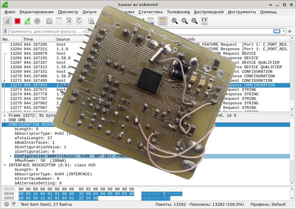
ConfigurationDescriptor
From the point of view of the host, the device represents a set of separate interfaces, each of which is designed to solve some problem. An interface descriptor describes its device and associated endpoints. Yes, endpoints are not described by themselves, but only as part of the interface. Typically, interfaces with a complex architecture are controlled by SETUP requests (that is, through ep0), in which the wIndex field corresponds to the interface number. The maximum is allowed to pocket the endpoint for interrupts. And from the data interfaces, the host only needs descriptions of the endpoints and the exchange will go through them.
There can be many interfaces in one device, and very different ones. Therefore, in order not to get confused where one interface ends and another begins, the descriptor specifies not only the size of the "header", but also separately (usually 3-4 bytes) the full size of the interface. Thus, the interface folds like a nesting doll: inside a common container (which stores the size of the "title", bDescriptorType and the full size of the content, including the title) there can be a couple of smaller containers, but they are arranged in the same way. And inside more and more. Here's an example of a descriptor for a primitive HID device:
static const uint8_t USB_ConfigDescriptor[] = {
ARRLEN34(
ARRLEN1(
bLENGTH, // bLength: Configuration Descriptor size
USB_DESCR_CONFIG, //bDescriptorType: Configuration
wTOTALLENGTH, //wTotalLength
1, // bNumInterfaces
1, // bConfigurationValue: Configuration value
0, // iConfiguration: Index of string descriptor describing the configuration
0x80, // bmAttributes: bus powered
0x32, // MaxPower 100 mA
)
ARRLEN1(
bLENGTH, //bLength
USB_DESCR_INTERFACE, //bDescriptorType
0, //bInterfaceNumber
0, // bAlternateSetting
0, // bNumEndpoints
HIDCLASS_HID, // bInterfaceClass:
HIDSUBCLASS_NONE, // bInterfaceSubClass:
HIDPROTOCOL_NONE, // bInterfaceProtocol:
0x00, // iInterface
)
ARRLEN1(
bLENGTH, //bLength
USB_DESCR_HID, //bDescriptorType
USB_U16(0x0101), //bcdHID
0, //bCountryCode
1, //bNumDescriptors
USB_DESCR_HID_REPORT, //bDescriptorType
USB_U16( sizeof(USB_HIDDescriptor) ), //wDescriptorLength
)
)
};
Here the nesting level is small, plus not a single endpoint is described - well, so I tried to choose a simpler device. Some confusion here can be caused by the bLENGTH and wTOTALLENGTH constants equal to eight- and sixteen-bit zeros. Since in this case macros are used to calculate the size, it would be strange to duplicate their work and count bytes by hand. How strange it is to write zeros. And constants are a noticeable thing, contributing to the clarity of the code.
As you can see, this descriptor consists of the USB_DESCR_CONFIG "header" (storing the full size of the content including itself!), The USB_DESCR_INTERFACE interface (describing the details of the device) and USB_DESCR_HID, which in general terms says what kind of HID we are rendering. And exactly what in general terms: a specific HID structure is described in a special descriptor HID_REPORT_DESCRIPTOR, which I will not consider here, simply because I know it too badly. So we will restrict ourselves to copy-paste from some example .
Let's go back to the interfaces. Considering that they have numbers, it is logical to assume that there can be many interfaces in one device. Moreover, they can be responsible both for one common task (say, the USB-CDC control interface and the data interface), and for fundamentally unrelated ones. Say, nothing prevents us (except for the lack of knowledge so far) on one controller to implement two USB-CDC adapters plus a USB flash drive plus, say, a keyboard. Obviously, the interface of the flash drive does not know about the COM port. However, there are pitfalls here, which, I hope, someday we will consider. It is also worth noting that one interface can have several alternative configurations (bAlternateSetting) that differ, say, in the number of endpoints or the frequency of their polling. Actually, that's why it was done: if the host thinks that it is better to save the bandwidth,he can switch the interface to whatever alternative mode he likes best.
Communication with HID
Generally speaking, HID devices simulate real world objects, which have not so much data as a set of certain parameters that can be measured or set (SET_REPORT / GET_REPORT requests) and which can notify the host about a sudden external event (INTERRUPT). Thus, in fact, these devices are not intended for data exchange ... but who stopped it when!
We will not touch on interrupts for now, since they need a special endpoint. But we will consider reading and setting parameters. In this case, there is only one parameter, which is a structure of two bytes, which, by design, are responsible for two LEDs, or for a button and a counter.
Let's start with a simpler one - reading on request HIDREQ_GET_REPORT. In fact, this is the same request as any DEVICE_DESCRIPTOR, only specific to the HID. Plus, this request is not addressed to the device as a whole, but to the interface. That is, if we have implemented several independent HID devices in one device, they can be distinguished by the wIndex field of the request. True, this is not the best approach specifically for HID: it is easier to make the descriptor itself composite. In any case, we are far from such perversions, so we will not even analyze what and where the host tried to send: for any request to the interface and with the bRequest field equal to HIDREQ_GET_REPORT, we will return the actual data. In theory, this approach is intended to return descriptors (with all bLength and bDescriptorType), but in the case of HID, the developers decided to simplify everything and exchange only data.So we return a pointer to our structure and its size. Well, a little additional logic like processing buttons and a request counter.
A more complex case is a write request. This is the first time we encounter additional data in a SETUP request. That is, the core of our library must first read the request itself, and only then the data. And transfer them to the user function. And I remind you that we have no buffer. As a result of some low-level magic, the following algorithm was developed. Callback will always be called, but we will tell it from which byte the data is now in the endpoint receive buffer (offset) and the size of this data (size). That is, when the request itself is received, the offset and size values are zero (there is no data). When the first packet is received, offset is still zero and size is the size of the received data. For the second, offset will be equal to the size of ep0 (because if the data had to be split, they do it according to the size of the end point), and size will be equal to the size of the received data.Etc. Important! If the data is accepted, it must be read. This can be done either by the handler by calling usb_ep_read () and returning 1 (they say “I thought there myself, don’t bother”), or simply returning 0 (“I don’t need this data”) without reading - then the library core will deal with cleaning. The function is built on this principle: it checks whether the data is available and, if so, reads them and lights the LEDs.
Data exchange software
Here I did not reinvent the wheel, but took a ready-made program from the previous article .
Conclusion
That, in fact, is all. I told the basics of working with USB using a hardware module in STM32, I also touched some rake. Considering the much smaller amount of code than the horror that STMCube generates, it will be easier to figure it out. As a matter of fact, I still haven't figured it out in Cube noodles, there are too many calls of the same thing in different combinations. Much better for understanding the option from EddyEm , from which I started. Of course, there is not without jambs, but at least it is suitable for understanding. I also boast that the size of my version is almost 5 times smaller than ST's (~ 2.7 kB versus 14) - despite the fact that I have not been involved in optimization and, for sure, you can still shrink it.
I would also like to note the difference in the behavior of various operating systems when connecting questionable equipment. Linux just works even if there are errors in the descriptors. Windows XP, 7, 10, at the slightest error, they swear that "the device is broken, I refuse to work with it." And XP sometimes even in BSOD fell out of indignation. Oh, yes, they also constantly display "the device can work faster", I don't know what to do about it. In general, no matter how good Linux is for development, it forgives too much, it is necessary to test on less user-friendly systems.
Further plans: consider other types of endpoints (so far there was an example only with Control); consider other controllers (say, I still have at90usb162 (AVR) and gd32vf103 (RISC_V) lying around), but these are very distant plans. It would also be nice to take a closer look at individual USB devices like the same HIDs, but also not a priority task.