The post contains instructions on how to connect a TFT-LCD display on the popular ILI9341 controller to a single-board computer based on Armbian OS using a Device Tree overlays without dancing with a tambourine. There is a lot of material on the Internet on how to connect various LCD screens to the Raspberry Pi. But what if you don't have a Raspberry Pi and want to connect an inexpensive LCD screen to the SPI interface? All you need is any Armbian-enabled board. The Armbian OS supported boards catalog includes boards: Asus, Pine64, Hardkernel, Orange Pi, Banana Pi, etc. At the moment, there are more than 114 models of boards in the catalog, support for various equipment out of the box is announced. Available for connection: 4G / LTE modems, USB Wi-Fi, USB Bluetooth, USB Ethernet, scanners DVB-tuners, etc. All these boards can be easily connected to SPI LCD display ILI9341,I ask how to implement this under cat.
Many single board computers have an HDMI output, but connecting a full display with HDMI input is expensive enough for a small project. In particular, if it is necessary to implement the minimum functionality of interaction with the user, a terminal for printing documents, displaying the current status of a running application. For such tasks, you can use LCD HD44780 character displays on the I2C interface, they are quite cheap and convenient. But at the same time, they are very limited in functionality, it is impossible to display the Linux console and the native UI of the application on these screens, in addition, the LCD screen area cannot be used as an information input panel. LCD screens on the SPI interface are perfect for solving these problems, a 3.5-inch display with a resistive layer can be purchased for $ 9.57 (including shipping).The LCD screen can display the Linux console and X11 subsystem. Thus, the use of SPI LCD is the best option in terms of functionality to cost.
Display ILI9341 2.2 inch 2.2 "SPI TFT
The ILI9341 controller is designed to control the TFT panel. The ILI9341 controller is supplied with panels with a diagonal of 2.2 to 3.2 inches, a resolution of 240x320, a resistive layer is added to some LCDs.
We will connect a 2.4-inch SPI LCD ILI9341 module without a resistive layer to a Banana Pi BPI-M64 single-board computer.
Consider the characteristics and pinout of SPI LCD ILI9341 2.4 inch
- 2.4-inch color screen, support 65K colors
- Resolution 320X240
- SPI connection interface
- SD card slot available
- module power supply 3.3V ~ 5V
- Logic control voltage 3.3V (TTL)
LCD connection pins
| Number | Pin label | Description |
| one | VCC | 5V / 3.3V power input |
| 2 | GND | Ground |
| 3 | CS | LCD chip select signal, low level enable |
| four | RESET | LCD reset signal, low level reset |
| five | DC / RS | LCD register / data selection signal,high level: register, low level: data |
| 6 | SDI(MOSI) | SPI bus write data signal |
| 7 | SCK | SPI bus clock signal |
| 8 | LED | Backlight control, high level lighting,if not controlled, connect 3.3V always bright |
| 9 | SDO(MISO) | SPI bus read data signal, if you do not need to the read function, you can not connect it |
To control the backlight, contact number 8 - LED is used . The maximum voltage of 3.3V corresponds to the maximum brightness from the total VCC supply. If it is necessary to set the screen brightness to 50%, then the voltage of 1.65V must be applied to the LED. To programmatically control the brightness of the backlight, the LED pin must be connected to the GPIO analog output on the single-board computer. If only digital outputs are available, only the option to turn on or completely turn off the screen backlight is available.
Based on the characteristics of the LCD screen, the following requirements are imposed on a single board computer:
- availability of SPI interface
- logic voltage on pins 3.3V (most boards)
- you will need two more (RESET, DC / RS) free GPIO pins
What kind of Armbian beast are you and what single board computer you need
The armbian.com/download page contains a wide variety of single board computers. From the point of view of ease of connection, it is better to choose a board with a 40-pin GPIO connector compatible with Raspberry Pi 3. For example, if you connect the SPI LCD ILI9341 2.4 inch to the Banana Pi BPI-M64 board and Orange Pi PC, then the numbers of the physically connected GPIO pins will be the same (not to be confused with the names of the processor contacts, they will be different, further required for configuration). If the single-board computer is not built on the Allwinner processor, then you may need to change more parameters in the file: sun50i-a64-spi-ili9341-led-always-on.dts (will be further in the text).
ArmbianIs the most popular Linux distribution for single board computers based on ARM processor, the list of supported boards is huge: Orange Pi, Banana Pi, Odroid, Olimex, Cubieboard, Roseapple Pi, Pine64, NanoPi, etc. Armbain distribution is based on Debian and Ubuntu.
After the appearance of the Raspberry Pi to the world, Chinese manufacturers decided to also join the Open Hardware Source movement, and made a lot of different boards. But the software support was extremely weak, the Armbian project was born to solve this problem. At the moment, Armbian is already 7 years old, 114 models of boards are supported, support for various equipment out of the box has been announced. Available for connection: 4G / LTE modems, USB Wi-Fi, USB Bluetooth, USB Ethernet, scanners DVB-tuners, etc.
To run Armbian on a single-board computer, you need to download an image from the site, then copy it to a microSD card, from which you will later need to boot. If the board has sufficient eMMC memory, then through the armbian-config utility, the operating system can be easily transferred from the microSD card to the eMMC memory along with the bootloader.
Creating an IoT project using Armbian, in contrast to the Raspberry Pi, allows you to choose boards that differ in performance and a set of peripherals. For example, all versions of the Raspberry Pi only have one Ethernet port. But if you need to make a router with several Ethernet ports, then from the list of supported Armbian boards, models are suitable: Helios64, Espressobin, Bananapi R2, etc.
Supported SoC
- Allwinner A10, A20, A31, H2 +, H3, H5, H6, A64
- Amlogic S805 and S905 (Odroid boards), S802 / S812, S805, S905, S905X and S912 (fork by @ balbes150)
- Actionsemi S500
- Freescale / NXP iMx6
- Marvell Armada A380
- Rockchip RK3288 / RK3328 / RK3399
- Samsung Exynos 5422
Wiring diagram SPI LCD ILI9341 2.4 inch to Banana Pi BPI-M64 (Raspberry Pi 3 GPIO port)
The SPI interface of the LCD screen is connected to SPI1 on the Banana Pi BPI-M64. CS, RESET, DC / RS contacts can be connected to any digital pins.
Connection pin table:
| LCD number | LCD label | Pin number on Banana Pi BPI-M64 (Raspberry Pi 3 GPIO port) |
| one | VCC | 1 or 2 (if you need maximum brightness, then contact No. 2 at 5V) |
| 2 | GND | 39, or any other Ground |
| 3 | CS | 24 |
| four | RESET | eighteen |
| five | DC / RS | 22 |
| 6 | SDI (MOSI) | 19 |
| 7 | SCK | 23 |
| 8 | LED | 1 or any free GPIO at 3.3V |
| 9 | SDO (MISO) | 21 |
If the LED contact is connected to the GPIO digital output, then to manually turn on the backlight, you will need to supply a logical "1" - to turn on or "0" - to turn off the screen.
Wiring diagram for SPI LCD ILI9341:

Banana Pi BPI-M64 Single Board Computer
Banana Pi BPI-M64 is a 64-bit quad-core mini single board computer supplied as an open source solution. The core of the system is an Allwinner A64 processor with 4 Cortex-A53 cores with a frequency of 1.2 GHz. The board houses 2GB DDR3 SDRAM 733MHz RAM and 8GB eMMC.
The most important thing for a successful SPI LCD connection is to know the name of the pins for the SPI interface, their number and name depends on the processor model. Allwinner A64 Datasheet is required for this task. The Banana Pi BPI-M64 Wiki page shows the pinout of the 40-pin GPIO connector, from which we learn the name of the pins: PD2, PD3, etc.
| 40 PIN GPIO of Banana pi BPI-M64 | |||
| GPIO Pin Name | Default Function | Function2 : GPIO | Function3 |
| CON2-P18 | PD4 | PD4 | |
| CON2-P19 | SPI1-MOSI | PD2 | UART4-TX |
| CON2-P21 | SPI1-MISO | PD3 | UART4-RX |
| CON2-P22 | PC0 | PC0 | |
| CON2-P23 | SPI1-CLK | PD1 | UART3-RX |
| CON2-P24 | SPI1-CS | PD0 | UART3-TX |
In addition to the name of the contact, it is necessary to find out the serial number of this contact on the processor leg, it is easily calculated by the formula: (position of the letter in the alphabet - 1) * 32 + output position. Let's calculate the leg number for the PD2 pin. The first letter is not counted because P - PORT, the position of the letter D in the alphabet = 4, we get (4-1) * 32 + 2 = 98. The contact with the PD2 label corresponds to the 98th foot on the processor, then it will be required to configure the device tree.
Device Tree (DT) in Linux
A Device Tree (DT) is a Linux data structure consisting of named nodes and properties that describe hardware that cannot be discovered by polling the hardware. The tree should include the name of the core processor, its memory configuration, and any peripherals (internal and external). DT is not used to describe software, although listing hardware modules causes driver modules to be loaded.
The heart of any development board or single board computer is the SoC. The SoC has many pins (legs) for connecting power lines and various devices.
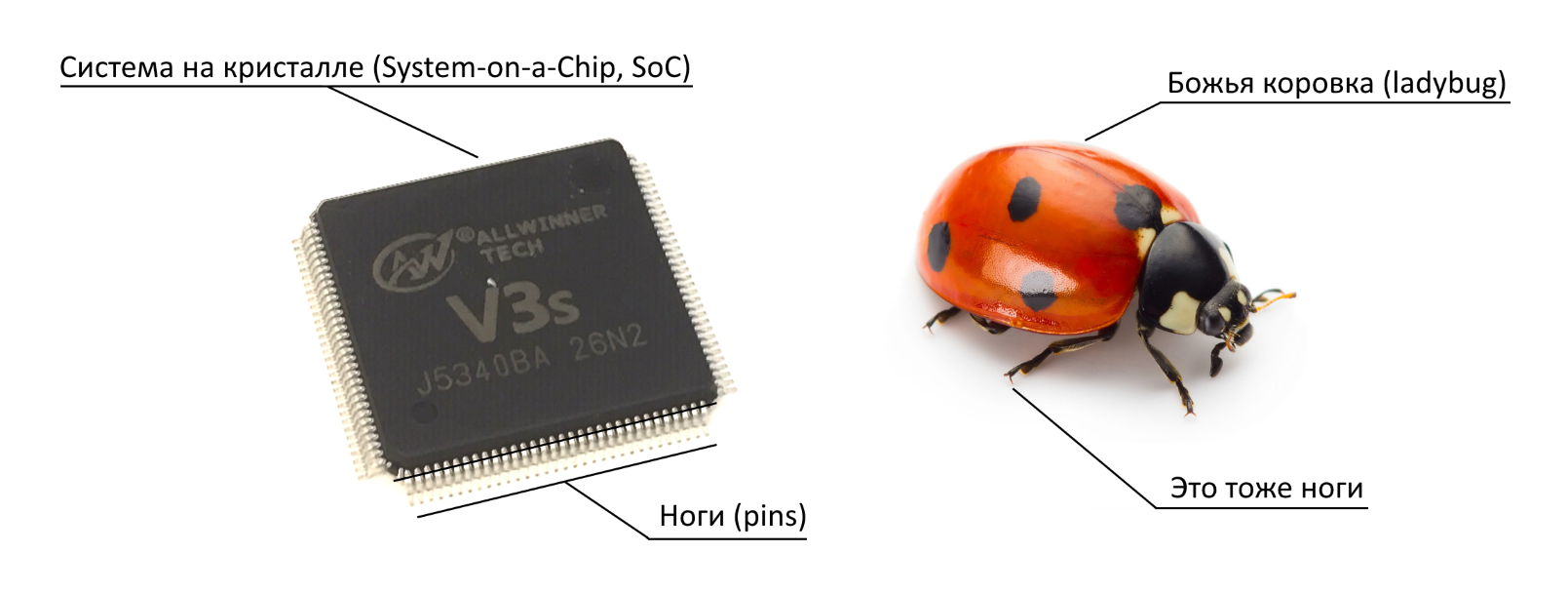
The pins can be linked together to form an interface such as MIPI DSI (MIPI Display Serial Interface). The MIPI DSI interface is designed to connect LCD panels, it is actively used in smartphones and tablets. But if you do not plan to connect a display to the device via MIPI DSI, then these lines can be used for other purposes by changing the DT. Unlike the x86 architecture, SoC-based systems do not have the ability to fully identify all devices in Plug and Play mode. Therefore, it is necessary to explicitly declare which pins are used for interfaces and which devices are connected to these interfaces.
Before the advent of DT, device information in Linux was an integral part of the kernel, and in the event of a change in the composition of peripheral devices, it was necessary to rebuild the system image. This was extremely inconvenient, and therefore the description of peripheral devices was moved to configuration files that are collected at the logical level in a tree. Where branch is a device with an indication of the driver required for the operation of this device.
After using DT, there was no need to create an individual image for each set of peripheral devices. Now it is enough to create one image, include a set of drivers for various devices, and create its own DT for each device.
Device tree overlays
Device Tree overlays - Add the principle of overlapping device layers to the DT. If the configuration describes the UART interface to which Bluetooth was connected, and it is necessary to replace Bluetooth with a GPS module, then you can not delete the existing Bluetooth settings, but add an additional layer for the GPS module that will override the previous settings.
The following terms are used to work with DT:
| DT | Device tree |
| DTB (* .dtb) | Device tree binary file |
| DTBO (* .dtbo) | Device tree binary for overlay |
| DTC | Device tree compiler |
| DTO | Device tree overlays |
| DTS (* .dts) | Source file for device tree |
| FDT | Flattened Device Tree, binary format contained in a .dtb file |
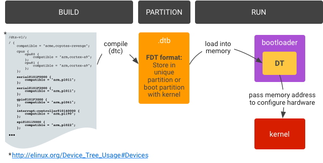
The hardware configuration is described in DT source files (.dts) then they are compiled into DT binaries (.dtb) for final use on the system. You can also perform the reverse procedure for decompiling *. dtb to *. dts, a compiler / decompiler is present on the system. DTO implementation includes device tree splitting, building, partitioning, and execution.
DT sharing
DT is divided into two parts:
- Main DT (main device tree) . Provided by the SoC developer and is the default setting. In this case, Allwinner is provided by the developer of the Allwinner A64 processor.
- Overlay DT (Overlay device tree) . The specific configuration of the board manufacturer includes the peripherals that are located on the board. The Banana Pi BPI-M64 board is provided by SinoVoip Co.,
The topic of Device Tree overlays in Linux is large enough not to turn the post into a multivolume work by Lenin, you can read in more detail in the publication Working with GPIO using the example of Banana Pi BPI-M64. Part 2. Device Tree overlays.
DTS shaping for SPI LCD ILI9341 2.4 inch
Testing was performed on the Armbian_20.08.2_Bananapim64_bionic_current_5.8.6_minimal.img.xz image , based on Ubuntu 18.04.5 LTS (Bionic Beaver), Linux kernel 5.8.6. uname: Linux bananapim64 5.8.6-sunxi64 # 20.08.2 SMP Fri Sep 4 08:52:31 CEST 2020 aarch64 aarch64 aarch64 GNU / Linux.
Armbian already has a driver for ILI9341, so all that is required is to create a DTS device description file, compile it to DTBO format, and reboot the SBC. As the saying goes Easy!
To generate a DTS file, you need to find out the link to the gpiochip in which the SPI interface is located, to do this, open the Armbian terminal and execute the command cat / sys / kernel / debug / gpio:
root@bananapim64:~# cat /sys/kernel/debug/gpio
gpiochip1: GPIOs 0-255, parent: platform/1c20800.pinctrl, 1c20800.pinctrl:
 gpio-120 (                    |bananapi-m64:red:pwr) out hi
 gpio-142 (                    |bananapi-m64:green:u) out lo
 gpio-143 (                    |bananapi-m64:blue:us) out lo
 gpio-166 (                    |cd                  ) in  lo ACTIVE LOW
 gpio-233 (                    |usb0_id_det         ) in  hi IRQ

gpiochip0: GPIOs 352-383, parent: platform/1f02c00.pinctrl, 1f02c00.pinctrl:
 gpio-354 (                    |reset               ) out hi ACTIVE LOW
 gpio-356 (                    |shutdown            ) out hi
 gpio-357 (                    |host-wakeup         ) in  lo
 gpio-358 (                    |device-wakeup       ) out hi

gpiochip2: GPIOs 510-511, parent: platform/axp20x-gpio, axp20x-gpio, can sleep:
This command will list all available gpiochip devices and the affected pin numbers in the operating system. In the previous section, for the SPI1-MOSI pin, the name of the PD2 pin, the processor leg number was determined - 98. Based on the result obtained, the number 98 falls on the GPIOs range 0-255, which corresponds to the gpiochip1 chip : GPIOs 0-255, parent: platform / 1c20800. pinctrl, 1c20800.pinctrl . Further, to generate a DTS file, you need to find out the link to 1c20800.pinctrl .
Let's create a DTS file with the name: sun50i-a64-spi-ili9341-led-always-on.dts (based on the dts file for the Orange Pi PC board):
/dts-v1/;
/plugin/;

/ {
	compatible = "allwinner,sun8i-h3";

  fragment@0 {
    target = <&pio>;
    __overlay__ {
      ili9341_pins: ili9341_pins {
        pins = "PD4", "PC0"; /*RESET, DC_RS*/
        function = "gpio_out", "gpio_out" ;
      };
    };
  };

  fragment@1 {
    target = <&spi1>;
    __overlay__ {
      status = "okay";
      cs-gpios = <&pio 3 0 0>; /* PD0 */

      ili9341: ili9341@0 {
        compatible = "ilitek,ili9341";
        reg = <0>;
        pinctrl-names = "default";
        pinctrl-0 = <&ili9341_pins>;
        spi-max-frequency = <16000000>;
        rotate = <90>;
        bgr;
        fps = <25>;
        buswidth = <8>;
        reset-gpios = <&pio 3 4 1>; /*RESET=PD4*/
        dc-gpios = <&pio 2 0 0>; /*DC_RS=PC0*/
        /*led-gpios = <&pio 2 4 0>; LED=PC4*/
        debug = <0>;
      };
    };
  };
};
Consider the content:
- fragment@0 — /soc/pinctrl@1c20800, &pio. GPIO PD4", «PC0 gpio_out .
- &pio — GPIO /soc/pinctrl@1c20800, . Armbian : /boot/dtb-5.8.6-sunxi64/allwinner/sun50i-a64-bananapi-m64.dtb. DTS, : $ dtc -I dtb -O dts sun50i-a64-bananapi-m64.dtb -o sun50i-a64-bananapi-m64.dts
- fragment@1 — /soc/spi@1c69000, &spi1.
- status = „okay“ — SPI1
- cs-gpios = <&pio 3 0 0>; /* PD0 */ — CS SPI1.
- <&pio 3 0 0> — , &pio gpioiochip1 , P , PORT, D — 3 (: — 1), 0 3 , 0 PD0, 0 — , 0 ( 0 — , 0; 1 — , 1).
- compatible = „ilitek,ili9341“ —
- pinctrl-0 = <&ili9341_pins> — fragment@0
- spi-max-frequency = <16000000> - SPI interface frequency
- rotate = <90> - image orientation, rotation by 90 degrees, depending on how you want to position the display.
- fps = <25> - frames per second
- reset-gpios = <& pio 3 4 1> - RESET pin = PD4
- dc-gpios = <& pio 2 0 0> - DC_RS pin = PC0
Let's place the file on the path / boot / dtb / allwinner / overlay. Then compiles the .dts file to .dtbo:
$ dtc -O dtb -o sun50i-a64-spi-ili9341-led-always-on.dtbo sun50i-a64-spi-ili9341-led-always-on.dts
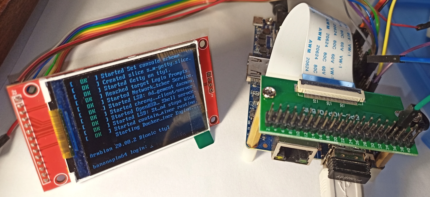
Let's start the board configuration utility: $ armbian-config. Go to the menu: System> Hardware, and turn on the layer (overlay): spi-ili9341-led-always-on . After rebooting the board, the Linux console will be on the SPI LCD screen:
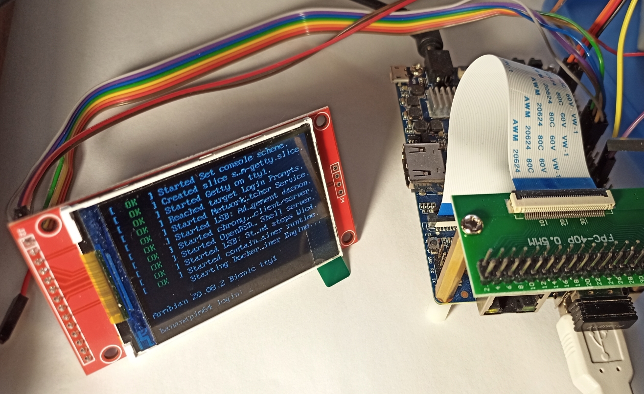
Midnight Commander and Htop on SPI LCD
Midnight Commander
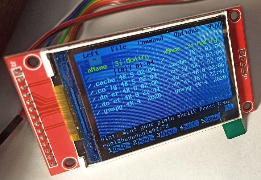
Htop

Htop
Contact name
For all Allwinner processors, the contact recording format corresponds to the form cs-gpios = <& pio 3 0 0> , for other processors the contact recording format will be different.
Solution of problems
If the image does not appear on the LCD, run the command to check: $ dmesg | grep -E 'ili9341'.
The console should contain the following information:
root@bananapim64:/boot/dtb-5.8.6-sunxi64/allwinner# dmesg | grep -E 'ili9341'
[    5.733989] fb_ili9341: module is from the staging directory, the quality is unknown, you have been warned.
[    5.734718] fb_ili9341 spi0.0: fbtft_property_value: buswidth = 8
[    5.734731] fb_ili9341 spi0.0: fbtft_property_value: debug = 0
[    5.734737] fb_ili9341 spi0.0: fbtft_property_value: rotate = 90
[    5.734744] fb_ili9341 spi0.0: fbtft_property_value: fps = 25
[    6.119287] graphics fb0: fb_ili9341 frame buffer, 320x240, 150 KiB video memory, 16 KiB buffer memory, fps=25, spi0.0 at 16 MHz
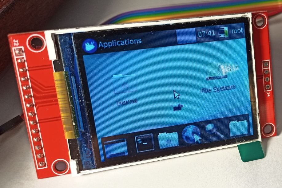
Configuring SPI LCD for Xfce GUI and X11 Subsystem
For Linux console output it is enough to add DTS file and that's it, but for graphics output it is not enough.
1) Install XORG and XFCE:
$ sudo apt-get update
$ sudo apt-get install xorg
$ sudo apt-get install xfce4
2) For the Allwinner processor, you must additionally install the GPU driver - fbdev:
$ sudo apt-get install xserver-xorg-video-fbdev
3) Delete all configuration files along the path /etc/X11/xorg.conf.d (if there are no files, then great)
4) Create a configuration file along the path /usr/share/X11/xorg.conf.d/99-fbdev. conf and place the following snippet in it:
Section "Device"
  Identifier "myfb"
  Driver "fbdev"
  Option "fbdev" "/dev/fb0"
EndSection
Where / dev / fb0 is the SPI LCD device. If an HDMI panel is connected to the board, then there may be two devices / dev / fb0 and / dev / fb1.
We start the graphical interface with the command: startx or startxfe4:
If you need to go directly to the graphical interface, then you must additionally install the packages:
$ sudo apt-get remove tasksel
$ sudo apt-get remove xubuntu-desktop
To return the console only startup, you must disable the autostart of the display-manager.service service
$ sudo systemctl disable display-manager.service
Solution of problems
If the graphical interface does not start, then in order to solve the problems, you need to look at the X11 event log using the command:
$ cat /var/log/Xorg.0.log
Outcome
Installing and configuring SPI LCD does not require any compilation of modules from source, which greatly simplifies installation. The main thing is to carefully expose the contacts and everything will work out of the box. The set goals have been successfully achieved.
RoadMap
- Connecting a larger 3.5 '' display on the ILI9488 controller.
- Configuring the Touch interface for Xfe.
- Displaying only one graphical application on SPI LCD using X11 subsystem from Docker container (solution for public terminals, kiosks, POS terminals).
File sun50i-a64-spi-ili9341- led-always-on.dts and other wood overlay files are available in the catalog GitHub Banana-Pi-BPI-M64 / dt-overlays /