In our home workshop we have a Jet GBH-1340A metal lathe with a digital readout device (DRO). We have been discussing the possibility of adding CNC to it for a long time, because without computer control, some types of parts are extremely difficult to produce with high precision. The article tells about the experience gained in this process, including mistakes made and recommendations for avoiding them, and also reveals in detail the entire process from the initial assembly to the finished result.
Training
Nevertheless, we approached the project with some degree of procrastination. From the beginning, we selected a spindle VFD controller, NEMA 34 stepper motors and machine axis drivers based on what we found in our Tormach 770 milling machine. We also found a parallel port interface board for CNC control on the internet. One of the main criteria for choosing all spare parts was their cheapness, although in the end they had to overpay. As the saying goes, the miser pays twice.
The details arrived and were set aside for about a year due to the large number of other active projects. We only used this occasionally to take some measurements and think about the exact placement of the stepper motors. The sudden failure of the spindle motor of our Jet made us fully switch back to the implementation of our plans. It was then that we got out all the prepared parts and started reworking in earnest.
General project summary
Time Spent: Many Weekends
Difficulty: Advanced
Cost: $ 2,500- $ 2,800
Materials
- Metalworking machine with digital display device (DRO);
- Marathon 3-phase asynchronous motor # 145THFR5329 / $ 500, replaced the burnt out spindle motor;
- - Emerson Commander SK / $450;
- LPT-, C11G CNC4PC.com / $68;
- NEMA 34 (2 .) X- Z-, Model 34HS38-3008S / $110 ;
- (2 .) GeckoDrive G213V / $150 ;
- Linux ( linuxcnc.org). Pentium 4;
- ( ) Roxburgh ;
- - 40″ / $225;
- (4 .);
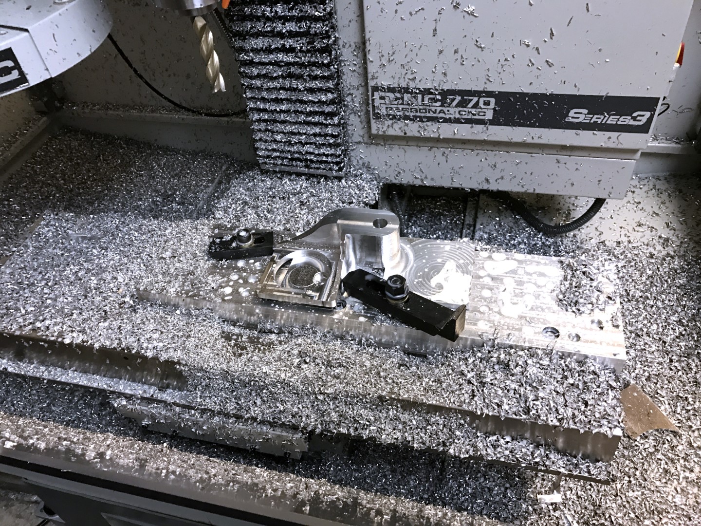
- (2 .), Tormach 770 ;
- (2 .), , Amazon $5 $50 ;
- , , 24″×16″×10″;
- Switches for power supply, protective shutdown, etc .;
- Wires: 12ga, 14ga and 22ga;
- Relays, switches, etc. from disassembled parts of the machine;
Tools
- CNC milling machine, end mills, boring bars, turning tools for machining motor mounts.
- Drill, screwdrivers, wrenches, wire strippers, crimpers, etc.
- Soldering iron and tin.
The entire reconstruction process was divided into three stages:
- Modification of the mechanism itself.
- Assembling the control unit.
- Installation and configuration of the control PC.
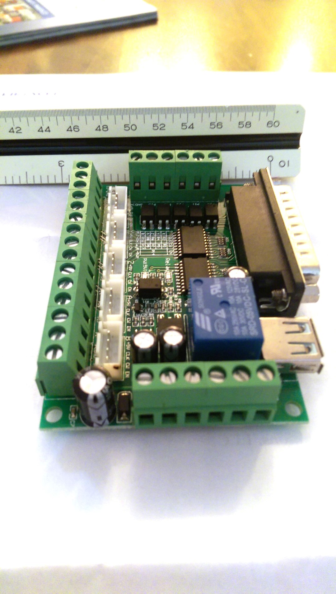
LPT Port Management Board / Interface Board
Machine modification. Part 1
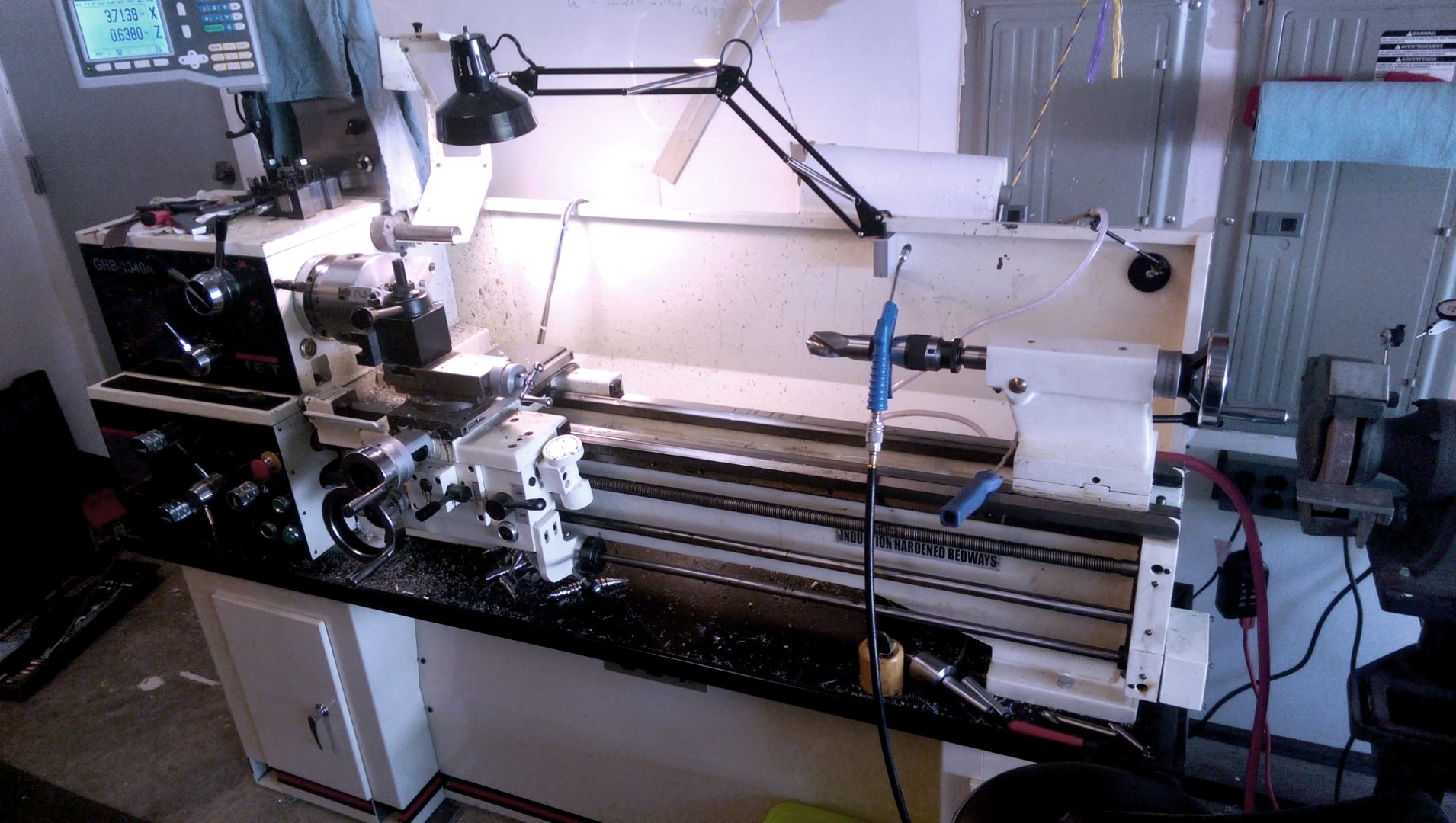
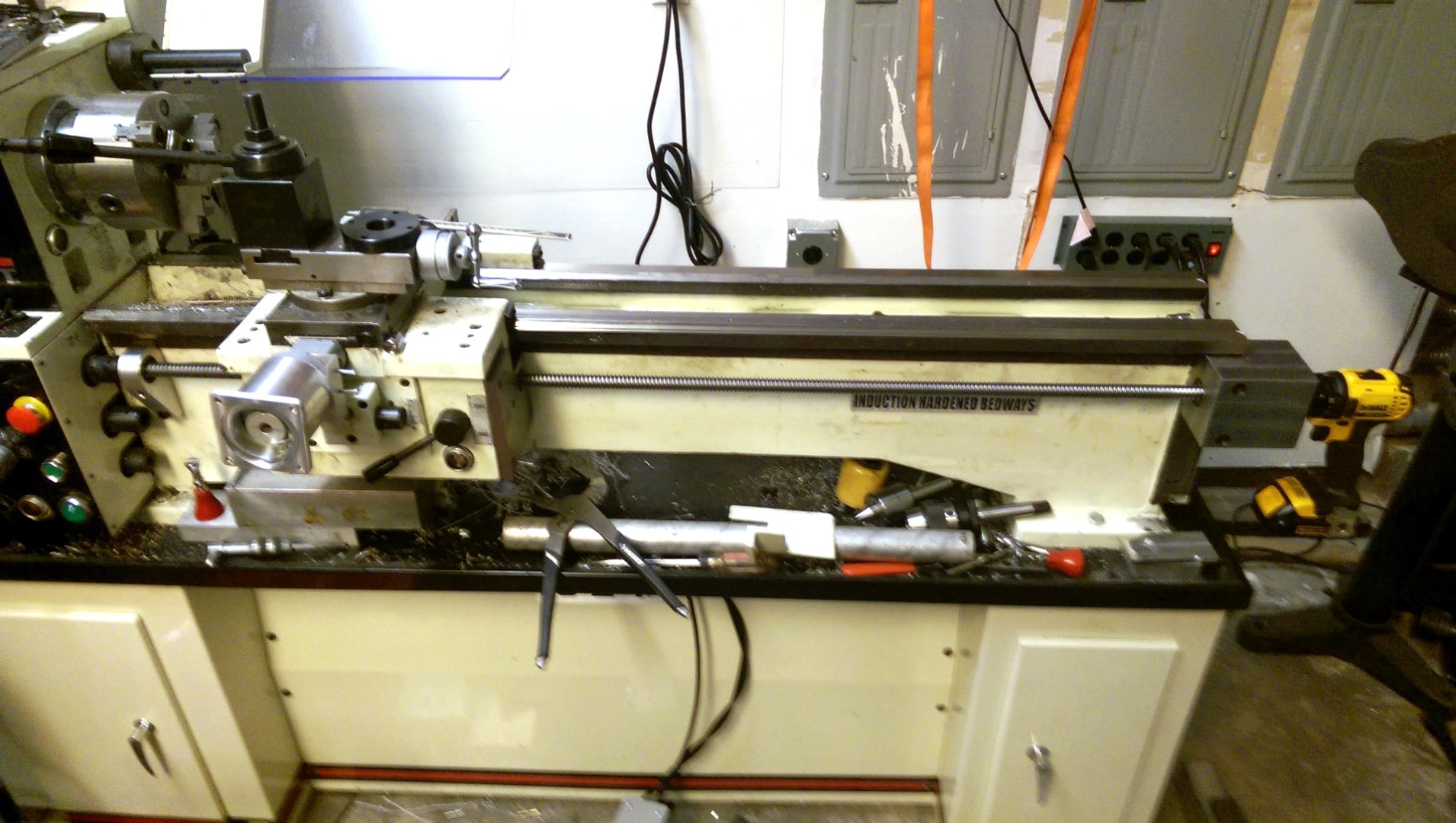
Our 40 "machine for metal before upgrade
This machine has the following characteristics: a distance between centers of 40" and a maximum possible workpiece diameter of 13 ". By default, the spindle speed is controlled through a gearbox located behind the spindle and driven by a 230V single phase motor. The gearbox did not need to be changed; we just chose the optimal transmission settings, and then, when using the CNC, the speed control will already be carried out by the controller of the frequency converter. The failure of the original single-phase motor, in fact, only played into our hands, since replacing it with a three-phase analogue gave aa greater degree of control and made it possible to double the maximum possible rotation speed, which for a dead motor was 1,750 rpm. The best part is that the frequency converter was able to convert 220V from one to three phases. The original control box was removed from the back of the machine and some of its control relays, along with other parts, migrated to the new one.
Milling the first Z-axis motor support
The carriage holding the cutting tools assumed two options for controlling its movement along the Z axis. (On a lathe, the Z axis goes from left to right, and the X axis is the cross feed axis). There is a main lead screw for general cutting and a second lead screw that rotates in sync with the threading spindle. Both screws are driven by a single gearbox and are used to move the carriage using the control levers on the carriage itself. We decided to remove the tapping screw and the shank driving the primary lead screw. This allowed us to drive the main lead screw using a stepper motor (SM) located at the opposite end and secured by pulleys with a belt. The main screw only needed a little over 50 rotations to move the carriage 1 ", and we figuredthat it will give some degree of control over the accuracy.
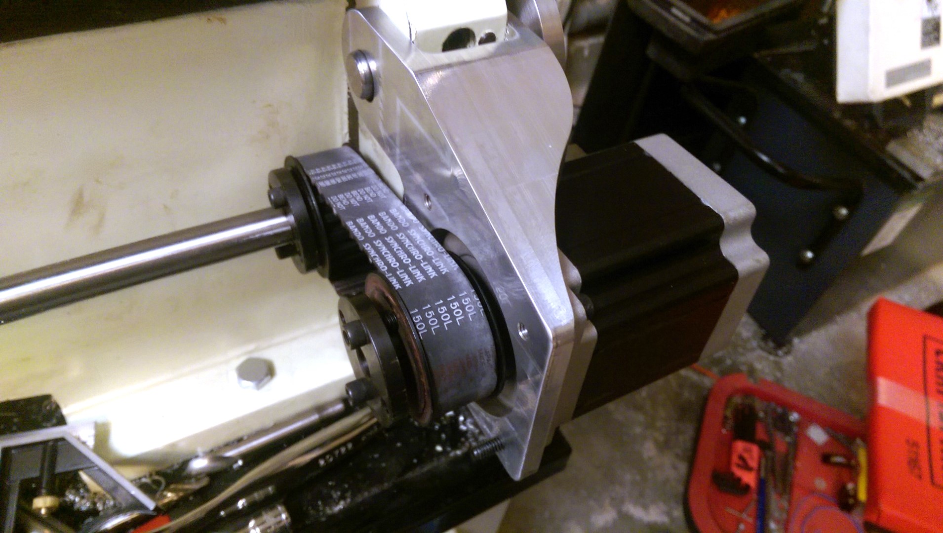
The first variant of the Z-axis motor drive
Using a CNC milling machine, we made a motor support, which is bolted to a lathe on a swivel, much like a generator in a car is installed to tension a belt.
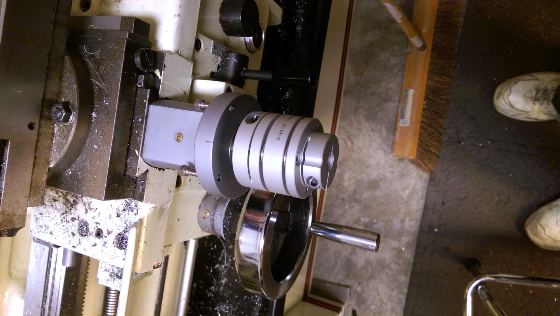
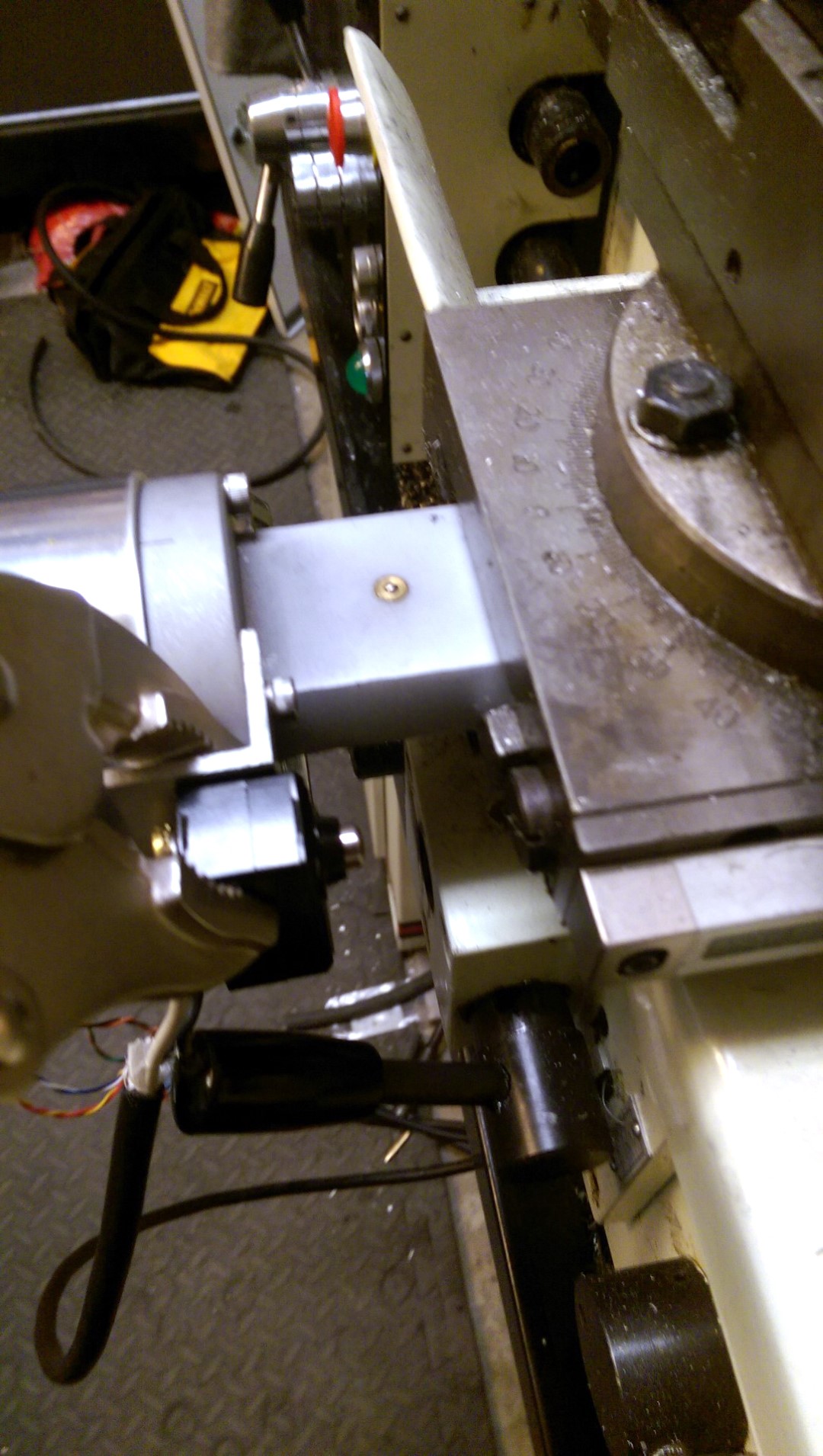
Replacing the cross feed: the X-axis main handle
For the X-axis, in other words, cross feed, direct drive from a stepper motor was the obvious choice. We removed the handles from the machine and milled another aluminum support. To soften the rigidity, the lead screw was connected to the stepper motor through a coupler.
Cross Feed Motor Assembly: New X-Axis Stepper Motor
We did not make any modifications in the tailstock of the lathe. It will remain under manual control while the computer does all the hard work in the X and Z axes.
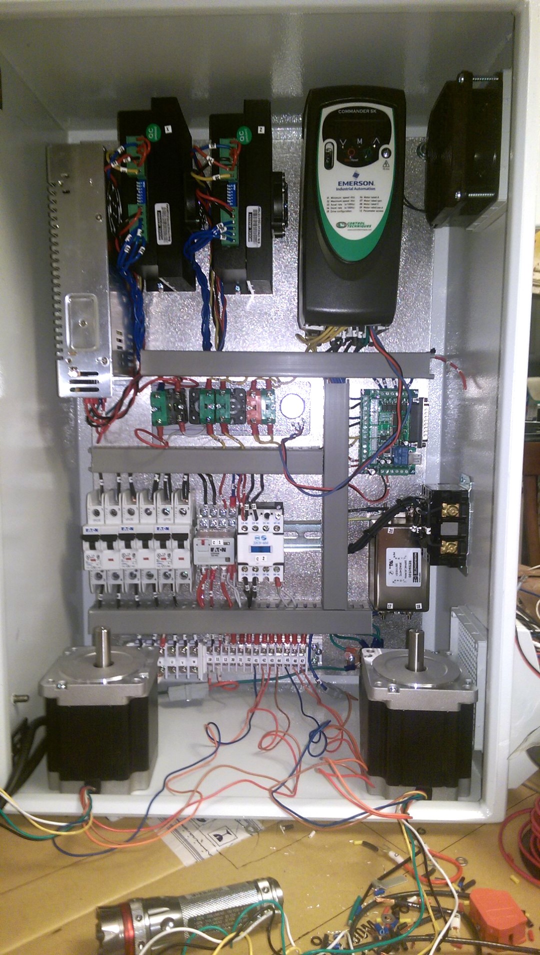
Assembling the control unit
The original unit was too small to hold all the components needed to operate the machine. Therefore, we ordered a 24 ″ × 16 ″ × 10 ″ case that would fit everything exactly. The 10 ”depth was perhaps overkill, but it did provide ample space for mounting cooling fans and switches on the side wall. At the same time, the body was rigid enough to hold the monitor on the back of the machine without falling over.
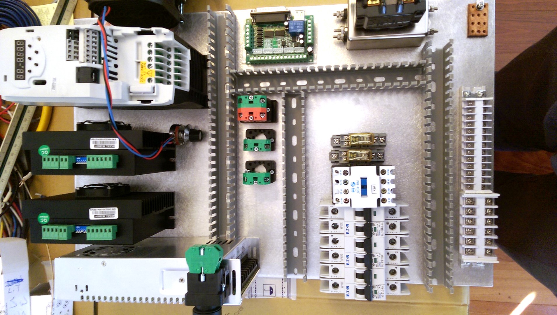
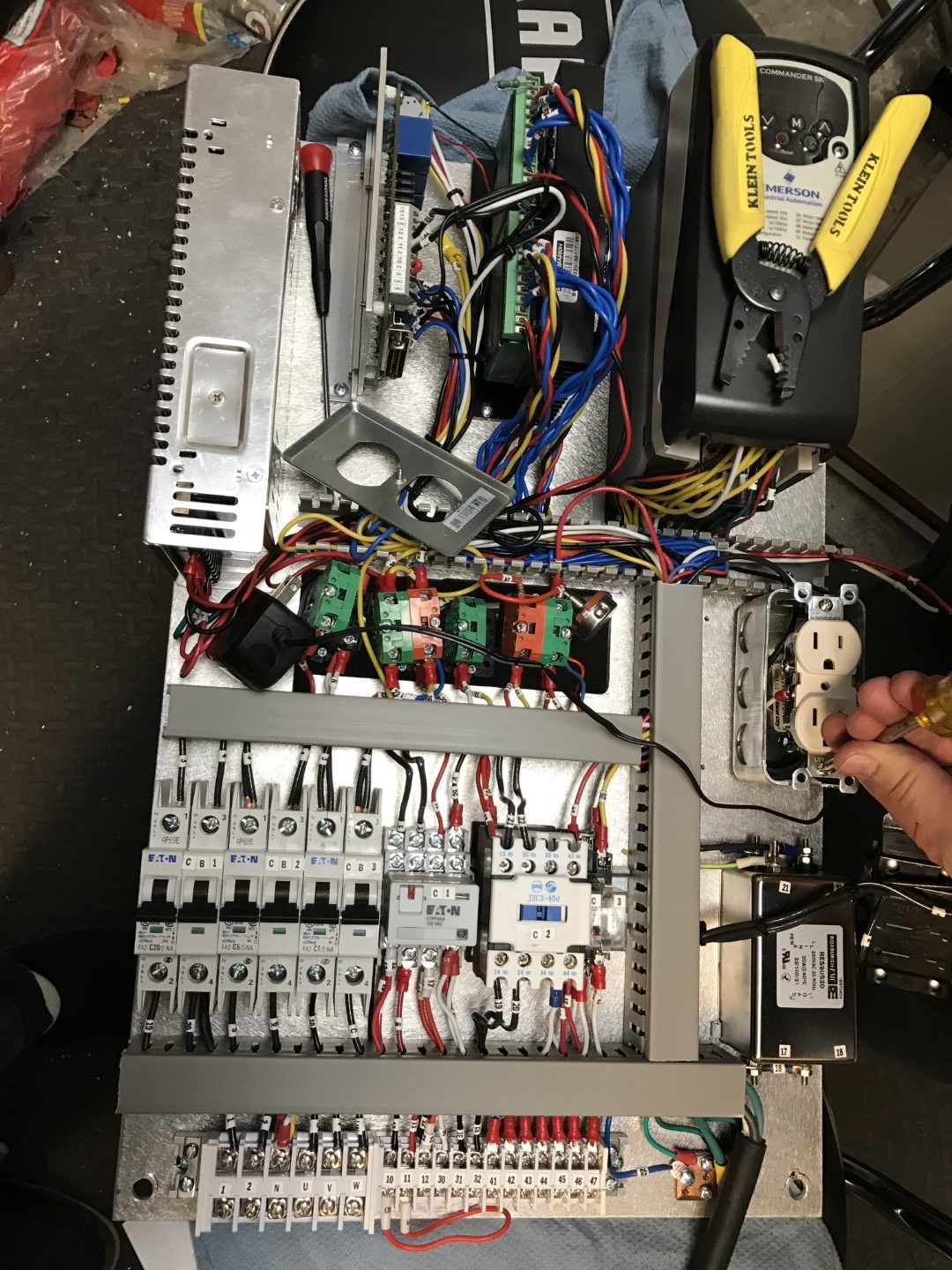
Location of controls
We secured all components to a 1/8 ”sheet of aluminum that could be removed from the case for easy access. In doing so, he also acted as a heat sink. For the elements of manual control of the spindle, we cut out the corresponding holes in the sheet and the body.
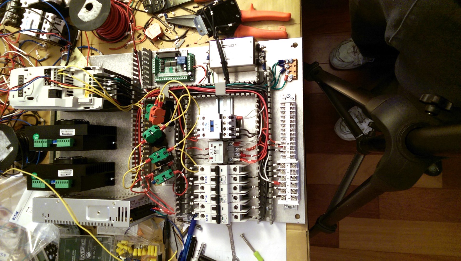
Wire routing
To avoid cable tangling, we have added cable ducts with open slots.
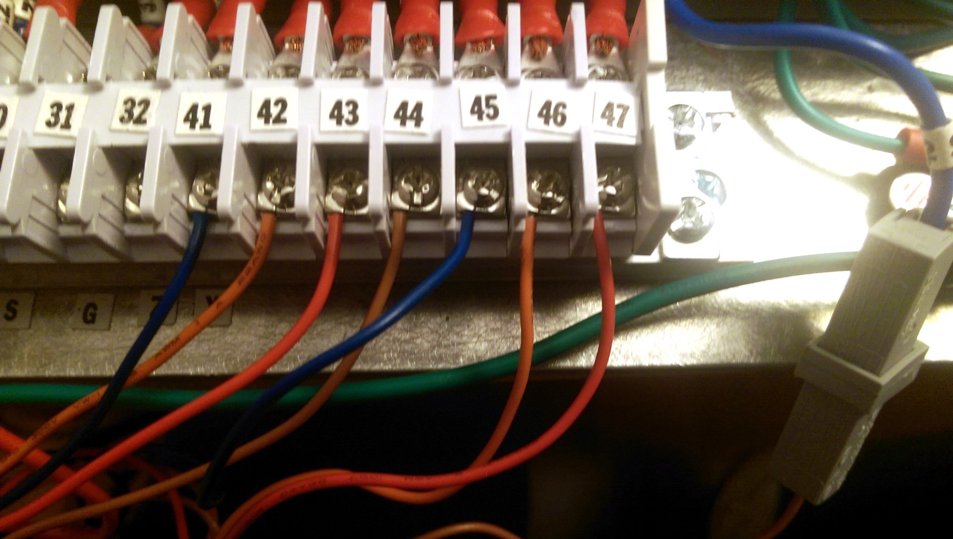
Carefully Marked Connection
Throughout the entire process, the diagram was processed in Visio, where all connections were carefully numbered and the wires were marked at both ends to match.
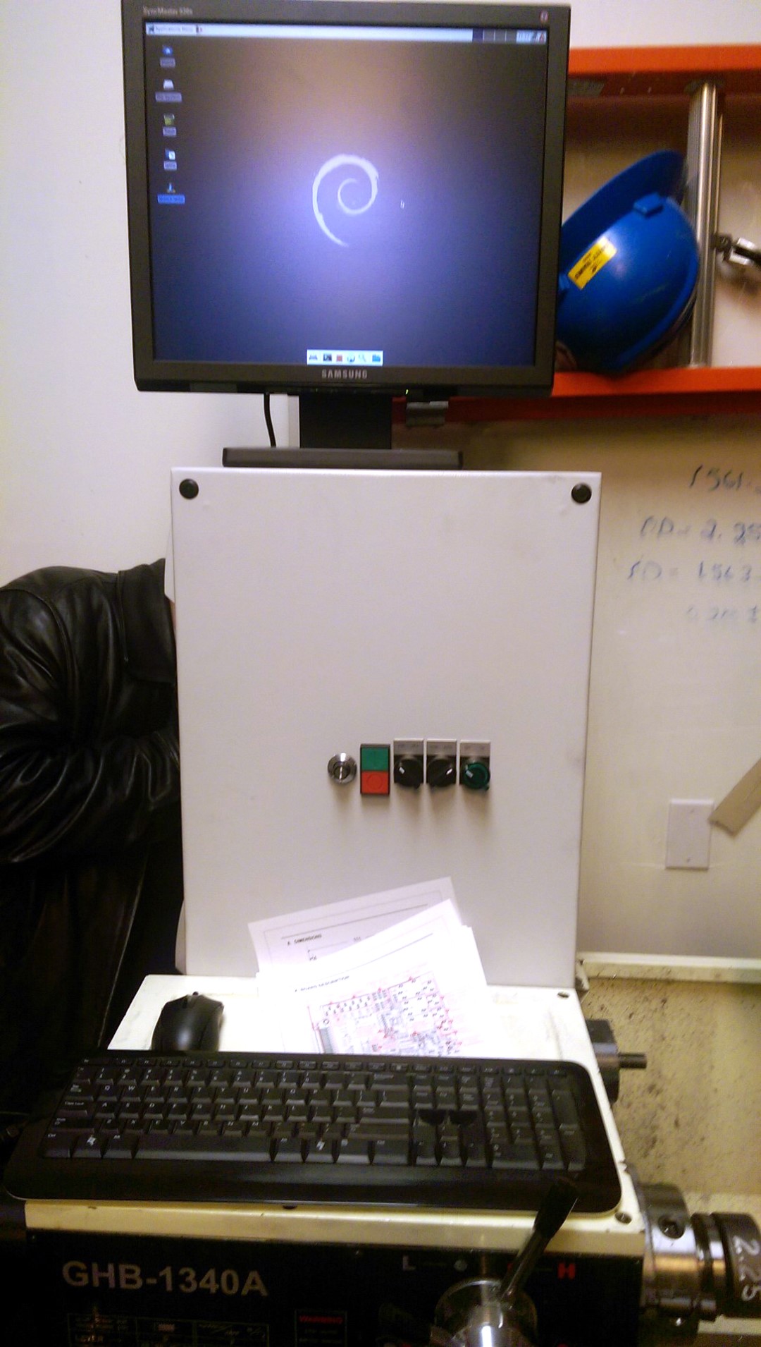
Assembled control box (with Stan's head inside)
Control box assembled. First testing
The whole process of assembling the control unit took about 60 hours.
Setting up the control PC
Although many CNC projects use a parallel port to control the device, they often do not use the latest high-performance hardware. Firstly, many modern PCs are not equipped with parallel ports, in addition, many of the modern processors are optimized in such a way that they work well with software, but are ineffective in direct implementation of I / O ports using bit-banging technology for time-sensitive hardware control. ... This is not a problem for the PC controlling the printer, because USB reduces the load, but in our case with a CNC router, an incorrect hardware / software configuration can lead to the fact that the cut will be made in tens of thousandths from the place where the G-code pointed ... (For example, due to missing steps, translator's note).
Fortunately, there are test lists for basic CNC software capabilities, so it was much easier to find. We chose an old Dell Optiplex with a Pentium 4 processor and LinuxCNC OS. We successfully purchased two of these PCs (one for spare parts) at a local used computer store for $ 30 each.
LinuxCNCoffers a very wide range of control options and is well supported by the PC enthusiast community. Following the instructions from the website, it turned out to be quite easy to install LinuxCNC, and this OS ran perfectly on our ancient PC. With the help of StepConf, we were able to configure the individual pins of the parallel port in any way we wanted. However, as it turned out, it was better to configure LinuxCNC before purchasing any control devices, since this OS offered pre-installed configurations for several types of equipment, some of which we simply did not know about during the initial purchases.
All this did not take long, and our board for the LPT port was already glowing like a Christmas tree when the keys were pressed, except that the magic smoke did not appear. And everything seemed to be clear, but ... nothing worked.
Miser pays twice
Still, it's not fair to say that nothing worked. There were hints of almost correct functioning of some of the components. One of the SD responded to the command to turn with a single dull sound. The driver of this engine even had a green LED up to this point, after which it switched to red. The driver of another stepper motor was defiantly burning red immediately when power was applied and continued to stare at us, like Sauron's eye.
We looked at all the wiring. We compared our version of its gasket with the version in Tormach. There were no problems here. And only later, after checking the output of the CNC control board using a borrowed oscilloscope, we found the first problem: the output signal voltage rose only to half of the level required by the stepper motor drivers. The board we bought for $ 20 turned out to be just rubbish. We decided not to skimp this time and found on another site another board worth $ 99. Upon her arrival, it turned out that she was marked by another site: CNC4PC.com. However, it also lagged behind the latest proposed version by 6 revisions. This board provided sufficient voltage, and we hoped that the motors would work better. But they were silent ...
I have already mentioned that much of what we bought for our own control unit was selected from samples from an existing milling machine. These stepper motor drivers were of the same MA860H model as in it. So, while imagining the invoices for the repair of this router, we began to replace the suspected parts by installing them in it. The stepper motors were the first, and to our relief, both worked great. The next to go to check were their drivers, and now none of them functioned. Sauron's eye continued to taunt us. Suspecting that it was our joint, we ordered a couple more drivers of the same model. Both were incapacitated immediately upon arrival. One refused to work at all in the milling machine, and the second provided rotation, but only in one direction. Obviously, these drivers were not a reliable solution.
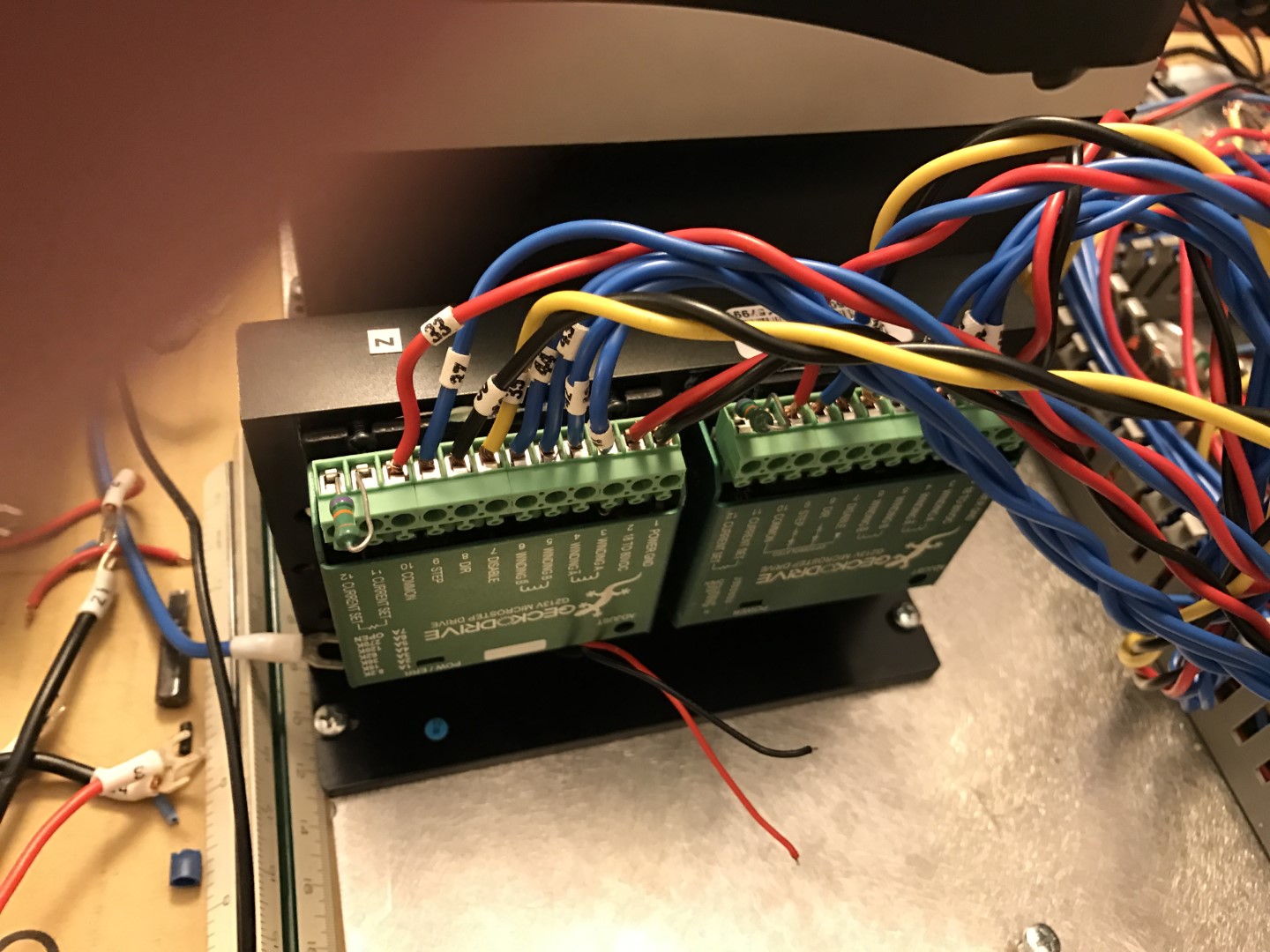
Frankenstein engine driver: new GeckoDrives installed in the framework of a non-working driver After a closer look at the
information on the Internet, we came up with GeckoDrive models that fully met our expectations. These boards worked great right out of the box, and both fit perfectly into the same footprint where there was one cheap driver previously. When properly energized, these boards required heat dissipation, which they were not equipped with by default. The remaining non-working analogs were just equipped with heat sinks and fans, which turned out to be their only working part. In the end, we just built the GeckoDrive boards into the empty frame of the dead driver, thus solving two problems at once.
Control parts assembled, but not yet housing
The new interface board was much larger than the original, and we could now replace one of the original stepper motor drivers.
A quick note on drivers: they come in analog and digital. You can find videos on YouTube comparing them at work. The video demonstrates, and we confirm this, that digital copies provide a much smoother and quieter engine operation. So their increased cost justifies itself.
Putting it all together
Everything was in its place. We could control the stepper motor using the UI buttons or G-code instructions, and with the simple attachment of the motors to the lead screws, it was possible to move the carriage along both axes.
We did not know the exact ratio of leadscrew speed to lateral displacement, so the correct settings for StepConf were sought by trial and error. This program asks for several values: motor steps per revolution, driver microstep, pulley tooth ratio and lead screw pitch. If you are not sure about these values, keep in mind that they are multiplied by one value, which means “steps per inch”. If all of these values except one (no matter which one) are set to 1, then in the end the remaining value will be a large number that can be adjusted with excellent accuracy.
To do this, we followed the following algorithm:
- Moving from left to right, move the carriage to the approximate known position. In the CNC UI, reset the offsets by setting the position value to 0.
- .
- G-code 1” , Z1.
- .
- « » , « ». , 20 000, 1.015”, 20 000/1.015 19 704 .
- , 1” 1”.
It is very important to take measurements after moving the carriage in only one direction because the lead screw will most likely have some play. If the measurement is carried out after moving in the opposite direction, the result will deviate up to the amount of backlash.
The digital indicator was still attached to the lathe, making it much easier to compare the instructions entered on the PC with the actual carriage movement. By following the algorithm we developed, we had to get a value of steps per inch that would give consistent results regardless of the axis on which the measurements were taken. This approach worked great for the X-axis, but when measuring the Z-axis, the results ranged up to 0.012 ”depending on where the measurements were taken. There was a serious mistake in something.
Machine modification. Part 2
The lead screws can be inaccurate, but the screw must be very bad so that the deflection increases and then decreases again along all 40 ”. The problem was that, in addition to the lead screw, other gears and worm gears were also involved in the movement along the Z axis. We needed to account for the imprecision in this whole related mechanism. The Z axis backlash was just as awful. LinuxCNC has ways to compensate for this, but this would require calculating the error at each point along all 40 ”axes. It was almost impossible to achieve the desired accuracy. The transmission had to be changed.
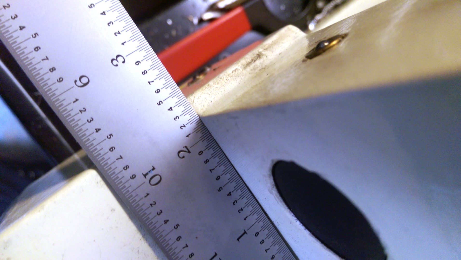
Measurements of the location for the location of the Z axis
A precision ball screw (ball screw) can almost completely eliminate backlash, the only question is the price. One company was offering ball screws for as much as $ 3,500. We ended up buying a ball screw and a nut for $ 225 from Roton Products in Missouri. In addition, it was required to adjust it to the bearings purchased earlier, which cost another $ 336 at a local grinding workshop. The backlash of this ball screw was already only 0.007 ”, but at least it did not change along the propeller length, which made it easy to compensate for this in LinuxCNC.
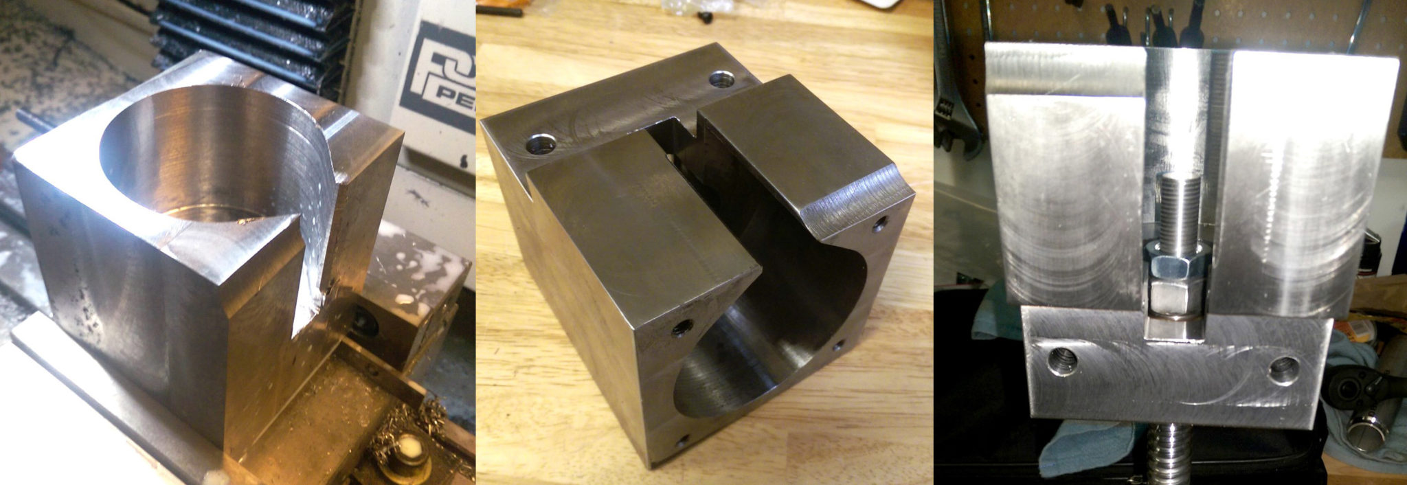
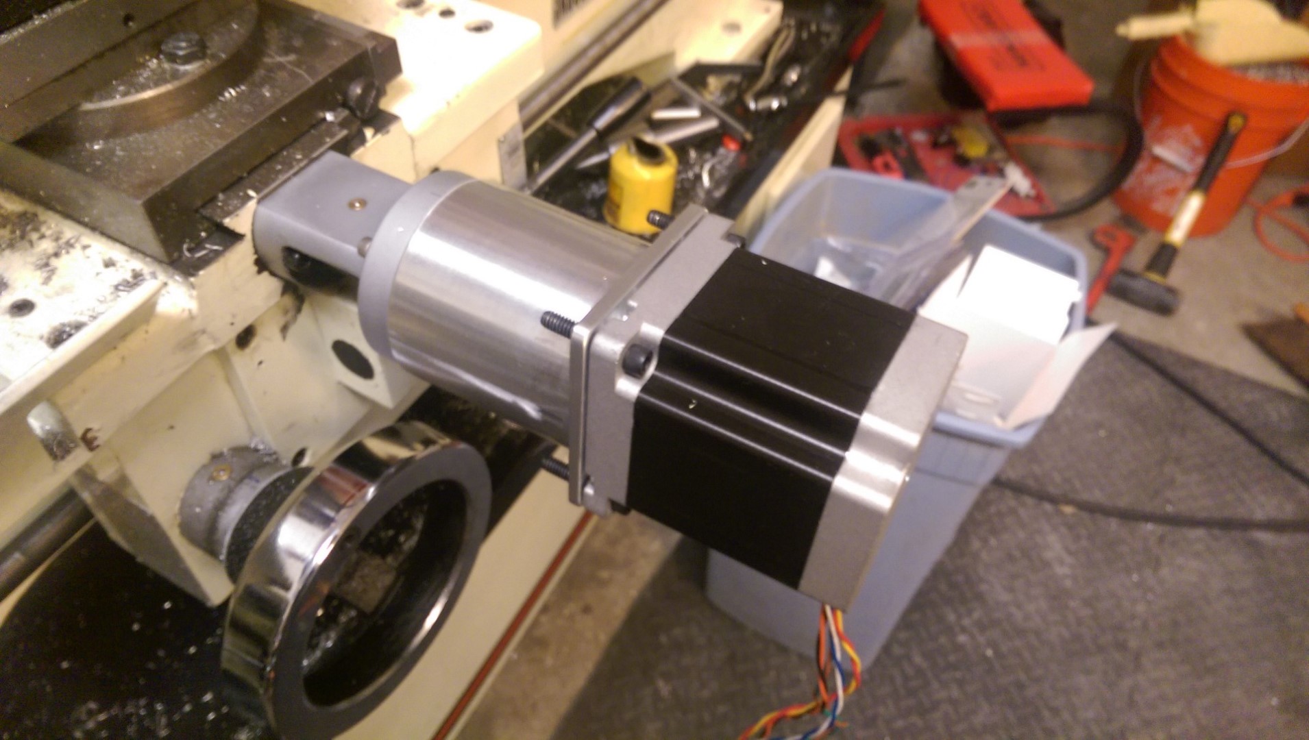
The second motor support of the Z axis: the middle is cut with a cutter, machined and mounted together with the ball screw
We also decided to remove the belt with the pulley and make a new fastening for the ball screw, so that the direct drive from the speed motor can be realized.
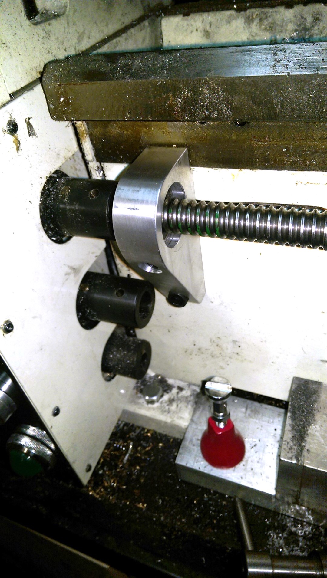
Z-axis ball screw head
Each end of the shaft is supported by a pair of thrust bearings fixed one-to-one to block movement while maintaining rotation. The shaft itself is secured between these two bearing supports under some interference.
Modified lathe with new supports prepared for the stepper motor
Any CNC requires limit switches so that the machine can find the home position on each axis.
Mounting the Limit Switch
Fortunately, when we disassembled the manual control box, we found two momentary switches ideal for this purpose, placed in a convenient position for each drive screw.
Wire routing is usually done through cable ducts, but for the X-axis we didn't do that, just letting the wires from the control box at the back to the X-axis powered from the front hang freely under the machine.
Finishing touches
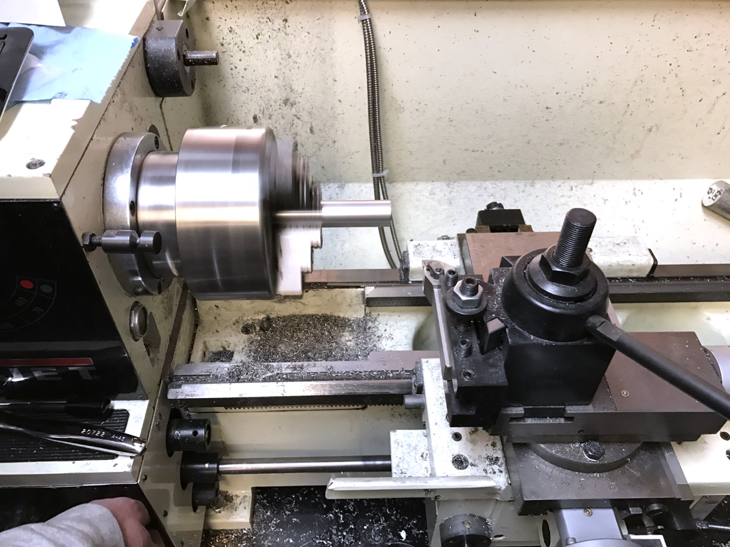
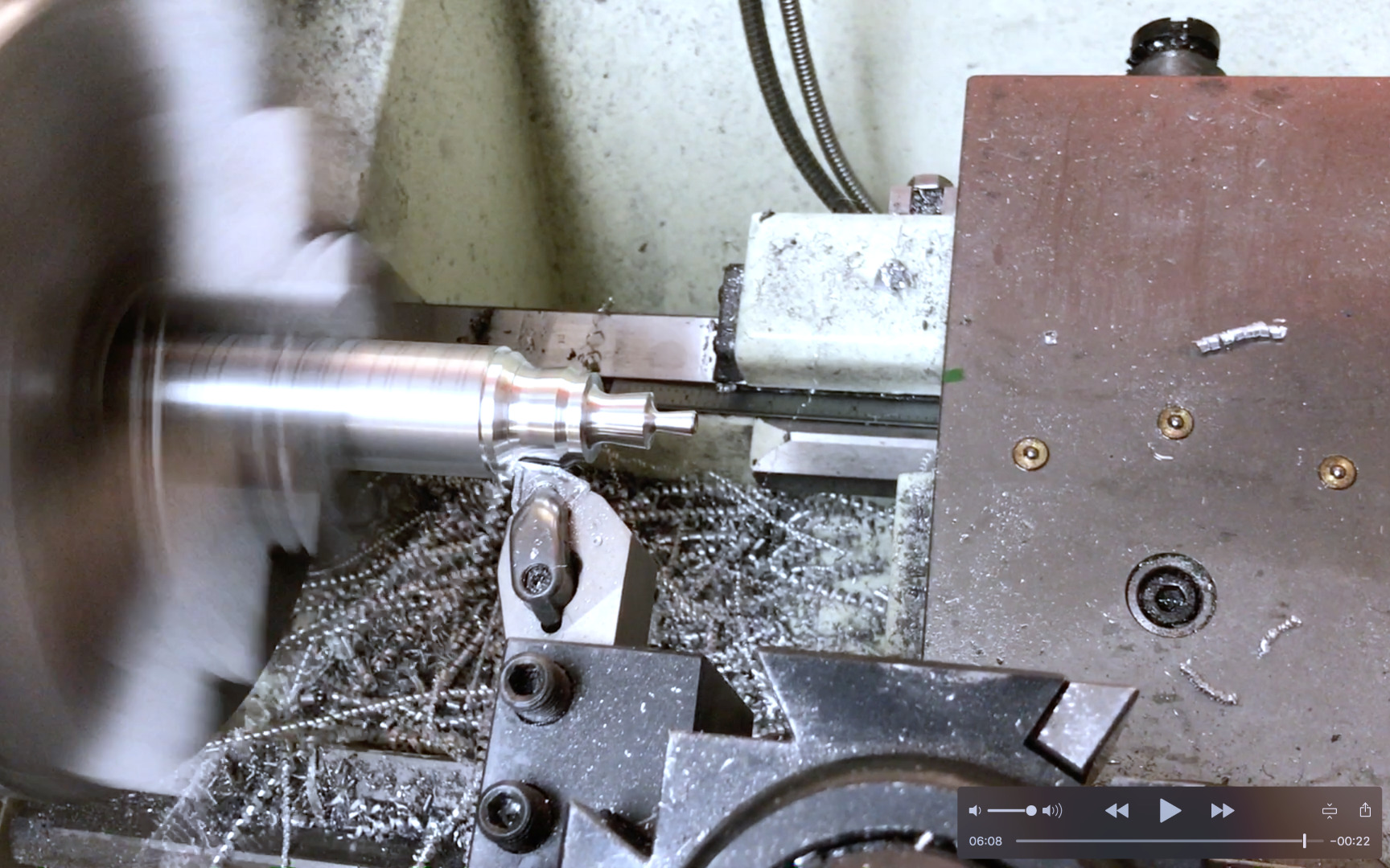
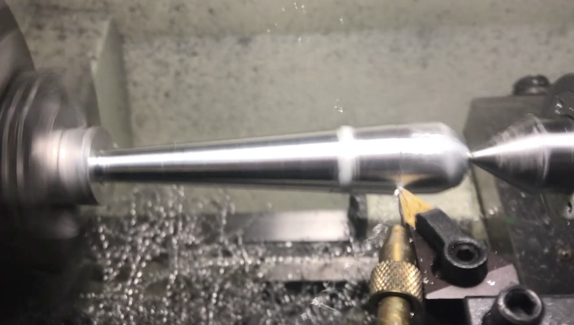
CNC lathe in action. Test run
We now had a fully functioning CNC lathe. LinuxCNC worked fine, even though its UI resembled an old Windows 98
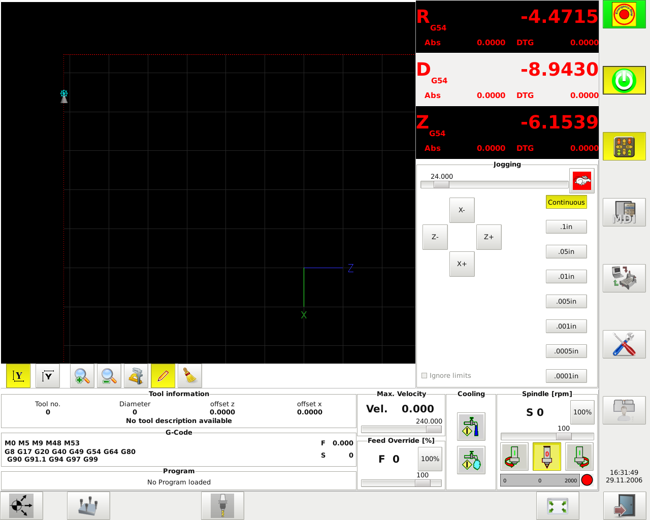
app. LinuxCNC screenshot (No program loaded until I figured out how to make it ignore the fact that it wasn’t connected to the machine)
Luckily, we did a little surfing the forums. two alternative UIs that looked and performed an order of magnitude better.
And as is usually the case with Linux, get ready to read tons of forums and documentation, and edit text files to get the configuration you want.
Knife sharpener. Handles are made on a CNC lathe!
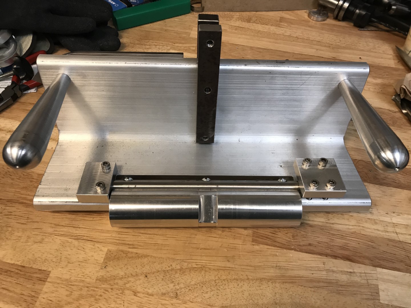
Finished tool for sharpening
In the future, we are planning some improvements:
- As a result of this project, the machine lost the ability to cut threads. However, LinuxCNC supports this feature if it is possible to implement feedback from the optical spindle speed sensor.
- It will be very useful to add liquid cooling with coolant (cutting fluid), even for an open machine running at low speeds.
- You can limit the backlash by ordering new ball nuts that have a different size of every fourth or fifth ball to reduce the tolerance between the ball screw and nut.
- The ball screws must be protected. To do this, you need to make suitable covers or at least brushes to clean it.
