Good day. In this post, I will explain how I managed to get the STM32F407VET6 to measure analog signals at specified times using DMA.
My main reason to measure signals at the exact time was the need to measure the currents flowing in the shunts of the three-phase BLDC motor controller.
To simplify and limit the problem, let us agree that
we know the exact moments in time when it is necessary to measure the signal;
from the previous point it is also clear how many measurements should be made;
the time difference between two successive measurements can be any;
we only need one channel to measure at precise intervals.
We also take into account the following features of STM32:
STM32 has a DMA (DMA1) controller that can save the MCU from transferring data from the ADC register to RAM memory at the end of the conversion;
ADC conversion can be triggered by some events including: TIMx_UP, TIMx_CCRy.
Thus, each subsequent conversion can be triggered when a timer that can trigger an ADC fires a Capture / Compare or Update event. After the end of the conversion, DMA1 comes into operation and transfers the measured value to the MCU memory.
, Capture/Compare CCR. ( ) . , . , , , .
CCR
Capture/Compare Register. Update , , . CCR , .
TIMx->CCRy DMA(DMA2), , CCRy ADC CCRy DMA2. ( DMA2, ADC DMA1) CCR, DMA2 TIMx->CCRy. .
, :
ADC CCRy, CCR ;
DMA1 ADC MCU;
DMA2 CCR ADC. DMA2 TIMx->CCRy .
CCR MCU, DMA.
:

, , . , STM32CubeIDE.
1. ADC Scan Conversion Mode, (IN1), DMA1, .

2. . AutoReload Register , .. . , , . TIM3 DMA, - , Increment Address Memory. TIM3 , , CCR DMA. Output Compare CH1 Output Compare No Output CCR CNT MCU.
Toogle on match TIM3 Output Compare Channel 1 CCR ADC. ADC : Trigger detection on both the rising and failling edges ADC .

3. , DAC, , DAC ADC IN1 , .
, .
DAC . , DAC (4095).
HAL_DAC_SetValue(&hdac, DAC_CHANNEL_1, DAC_ALIGN_12B_R, 0u);
__HAL_DAC_ENABLE(&hdac, DAC_CHANNEL_1);
CCR , , ARR, . , , .
CCR
uint16_t ccValues[MEASUREMENT_COUNT];
ccValues[0] = 115;
ccValues[1] = 252;
ccValues[2] = 388;
ccValues[3] = 475;
ccValues[4] = 582;
ccValues[5] = 646;
ccValues[6] = 727;
ccValues[7] = 871;
ccValues[8] = 993;
ccValues[9] = 1062;
ccValues[10] = 1211;
ccValues[11] = 1339;
ccValues[12] = 1425;
ccValues[13] = 1466;
ccValues[14] = 1541;
ccValues[15] = 1669;
ccValues[16] = 1818;
ccValues[17] = 1872;
ccValues[18] = 1963;
ccValues[19] = 2000;
CCR1, . CC1 .
htim3.Instance->CCR1 = ccValues[0];
HAL_TIM_Base_Stop(&htim3);
htim3.Instance->CNT = 0;
__HAL_TIM_ENABLE_IT(&htim3, TIM_IT_CC1);
__HAL_DBGMCU_FREEZE_TIM3();
ADC DMA. ADC .
HAL_ADC_Start_DMA(&hadc3, measuredAdcValues, MEASUREMENT_COUNT);
DMA2, , .. CCR1.
HAL_TIM_OC_Start_DMA(&htim3, TIM_CHANNEL_1, &ccValues[1], MEASUREMENT_COUNT - 1u);
.
MCU ( DAC/ADC IN1, TIM3_CH1) :

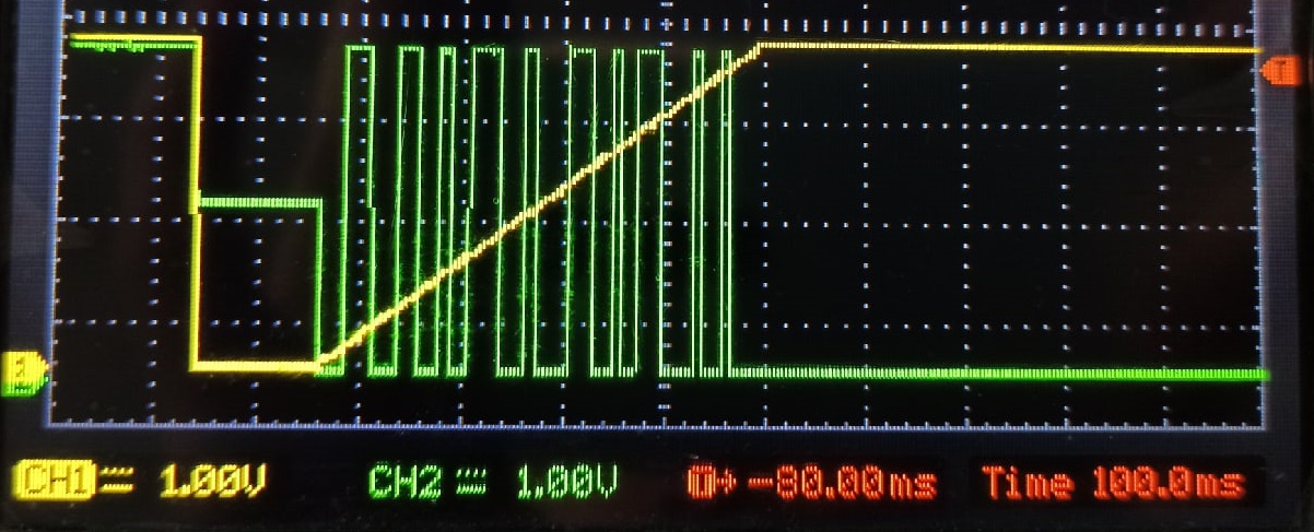
. , .
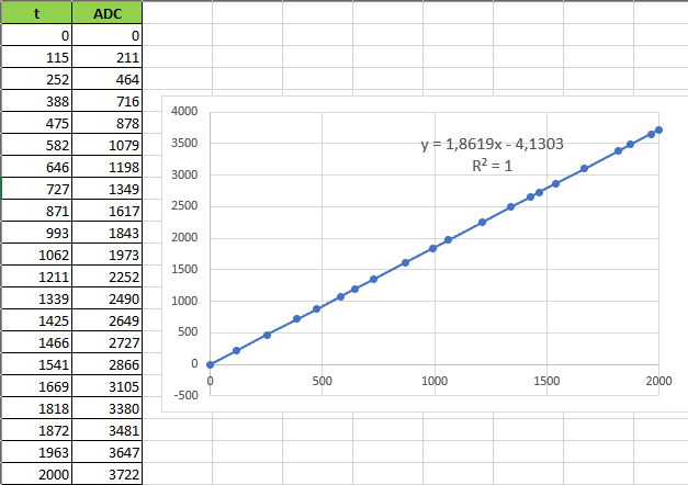
ADC , :

, , , , .
STM32F103C8T6, . CCR, MCU , . - , .
, DMA1, , DMA2 , . , , , .
Update 1:
Link to test case on github.