For over 5 years we have been using numerical simulation as a method for solving various engineering problems:
- determination of the parameters of technological processes that cannot be measured during field tests;
- evaluation of the efficiency of equipment and technologies planned for use;
- promoting new and unique products to customers;
- determination of requirements for mechanical characteristics of promising materials in future technologies
I, Oleg Kopaev , am in charge of numerical modeling at Severstal, and today I present to your attention a selection of the most interesting projects we have completed over the past year.
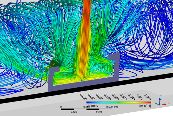
Simulation - the ability to study liquid steel flows in a tundish in a continuous casting plant
Testing various hypotheses- one of the most demanded areas of our work. There are always a lot of “breakthrough” ideas around: “our competitors have achieved…”, “the technology of the future is presented at the conference…”, “a new technological startup…”, some of them look very attractive economically. There are various ways to check which of these ideas can be applied in our company and will give the target profit, and which will not. You can take a chance, spend money and test the idea in the framework of pilot production. You can organize R&D with an external partner and hope for luck in choosing a contractor. However, practical experience shows that the most effective independent study of such initiatives by the forces of the company's specialized departments. And this is where numerical modeling becomes an integral part of the decision-making process,which allows you to test the performance of an idea with relatively little time and money.
This approach was used by us in a project to assess the possibility of winding steel pipes on a reel. Steel pipes in reels are widely used in the construction and repair of gas and oil wells. They allow you to save on assembly / disassembly of the drill string. These pipes are produced in relatively small diameters, up to 100 mm. We were asked the following questions:
- Is it possible to produce and supply pipes to customers in coils of larger diameter, for example, for the construction of local pipelines, help to save on welding?
- What are the maximum diameters and wall thicknesses that can be provided, from which steel grades?
- How much effort is required to wind and unwind such a pipe?
- We were able to answer all these questions by creating a finite element model that simulates the coiling process and allows us to vary the control parameters of the process.

On the left - incorrect process parameters, local collapse and destruction of the pipe. On the right - a pipe with a diameter of 219 mm and a wall thickness of 6.5 mm is wound onto a drum with a diameter of 4 meters.
Most of all, we love projects about explosions and destruction , so we were happy to start creating a model for polygon testing of large-diameter pipes. Companies operating main gas pipelines are interested in the fact that in the event of an emergency (you can google pictures and videos for the request "explosion on a gas pipeline") a section of a pipe with a minimum length that can be quickly repaired is destroyed.
Now, large-scale field tests are being carried out to assess the crack resistance of pipes. The meaning is simple - a section of the pipeline is assembled at the landfill, a high pressure is created in it, a shaped charge is detonated in the central part of the test section of the pipeline, the length of the formed crack in each direction is determined.

General layout of the test area
Unfortunately, the test results have always been poorly predictable, since now there is no unambiguous relationship between the laboratory properties of the pipe metal and the success of field tests. In order to find out whether the selected steel grade is suitable, we need to smelt (at least 350 tons of steel), roll sheets, make pipes from them, deliver them to the landfill, and only then we can find out the result.
The task for modeling is to create a tool that, based on laboratory tests of a steel sheet, will make it possible to accurately determine the result of field tests.
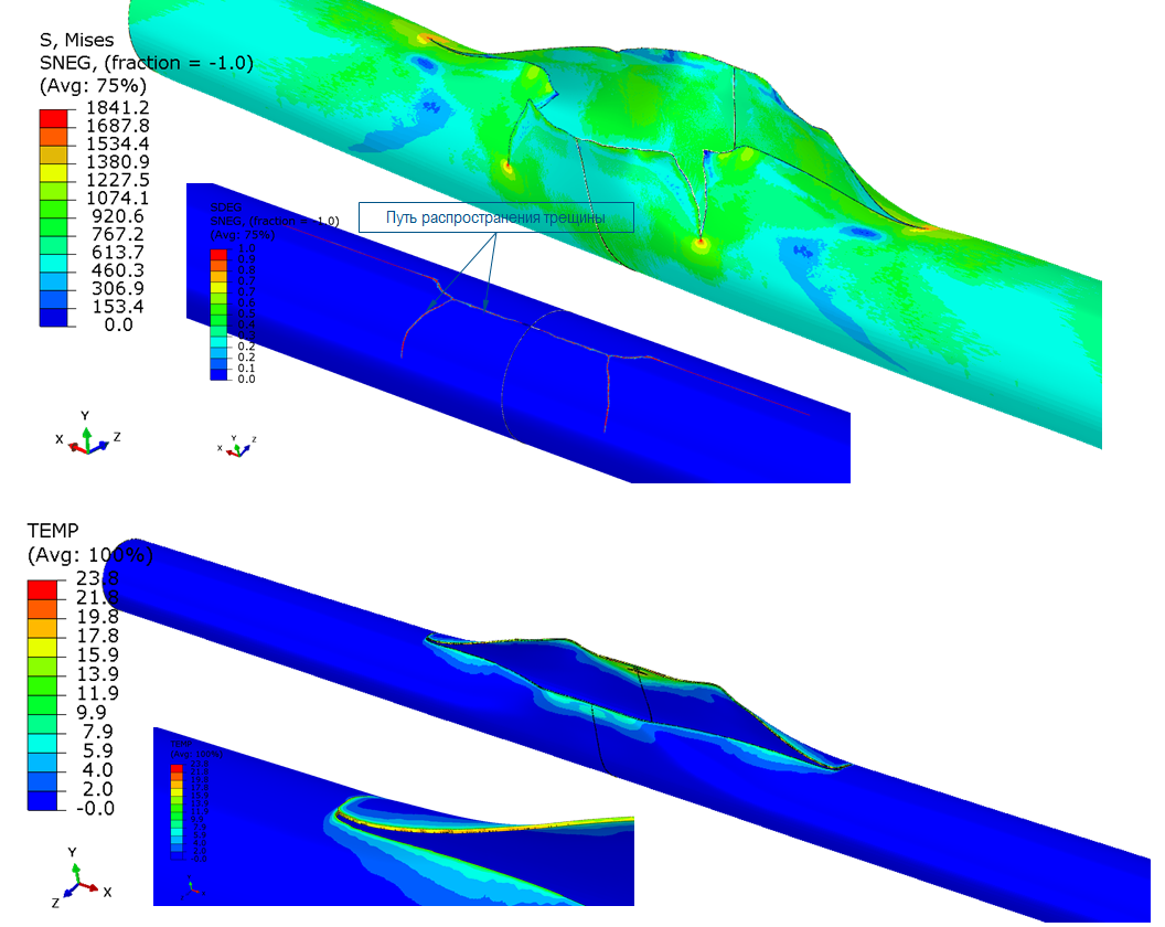
Results of virtual tests. Depending on the mechanical properties of the pipe, the crack can propagate linearly or loop back
We managed to create such a tool, and we are conducting virtual tests of our strongest X100 steel pipes for main gas pipelines, these pipes are not yet used in Russia. In addition, we plan to develop a method for calculating the resistance of pipes to crack propagation based on laboratory tests and offer it to our partners and customers.
Among our tasks are calculations of metal forming processes, which are more common for ferrous metallurgy. ... Calculations of such processes are done, probably, by every student studying in a profile specialty, many books and dissertations have been written. But for various reasons, these calculations often use significant simplifications and assumptions, for example: “cylindrical rolls”, “absolutely rigid rolls”, “stand frame is absolutely rigid”, “roll geometry is constant”.
Such simplifications would not allow us to carry out another project - to determine the optimal roll profiling of the hot-rolling mill stand, which would allow us to minimize stress in the roll and the probability of its failure. Therefore, in our model:
- the geometry and operation of the stand correspond to reality;
- the bed is deformable;
- rolls are profiled;
- the rolls are deformable, an anti-bending force is applied to the work rolls;
- the wear of the roll surface during the rolling campaign is taken into account.
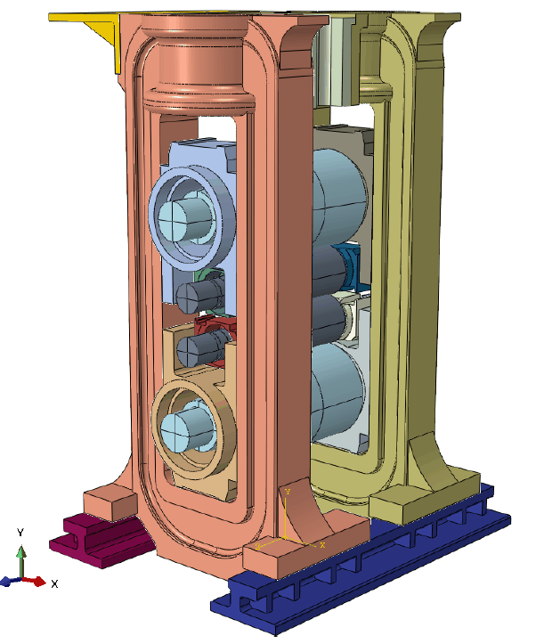
Model of the stand of a hot rolling mill
The created tool made it possible to study in detail the processes of loading and wear of the work rolls of a hot rolling mill, and to develop more efficient profiling.
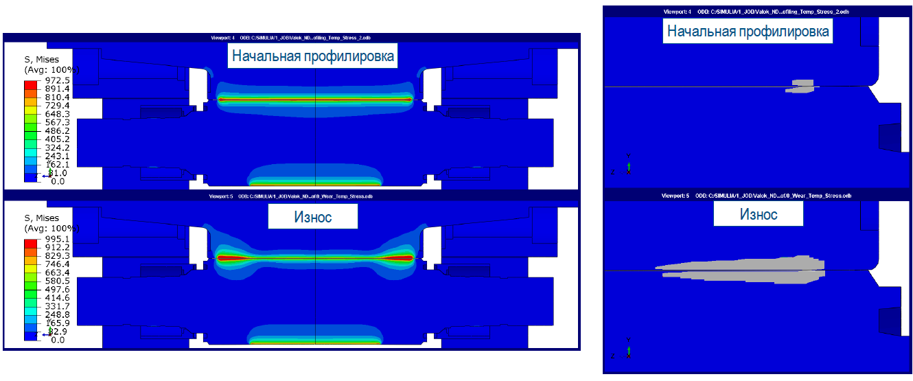
Stress distribution in the work rolls (left) and plastic deformation areas (right) at the beginning and end of the rolling campaign
In recent years, the repair departments of the company and our customers have developed a demand for analyzing the processes of equipment wear by bulk media . We carried out a pilot work on this topic together with our partner, KADFEM CIS, in a new software product called Rocky.
In the extraction of minerals, mining dump trucks of high carrying capacity are widely used, each of them daily performs dozens of trips, including loading ore or waste rock, transportation and unloading. The transported bulk media are highly abrasive, therefore, the dump truck body is lined from the inside with special wear-resistant steels, but even they require regular replacement.
Mining companies are interested in reducing lining wear and increasing its service life. There are two main courses of action:
- use of materials that are more resistant to wear;
- optimization of the geometry of the lining and / or the use of various schemes that change the nature of the movement of the bulk medium over the surface.
To assess the effectiveness of the use of various steels and geometric solutions, we have created and are developing a model of the body operation process. In parallel, a dump truck with experimental lining elements transports iron ore day after day and is approaching the moment of comparing the calculation and experiment results.

The process of unloading rock from the body of a mining dump truck
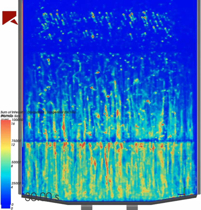
Distribution of energy spent on wear of the body lining
For those who like technical information, I would like to inform you that we are using SIMULIA Abaqus, Ansys CFD, Autoform software, Dell and Lenovo settlement stations, the newest of which have 64 cores and 256 GB of RAM. The optical 3D scanner came in handy. To determine the physical and mechanical properties of materials, we use our own laboratories and the laboratories of our partners, we actively share material data with our customers. One project can take from an hour to several months.
We still have many different projects in the works and in plans. Your feedback and comments will help us write more often and offer interesting information with illustrations.