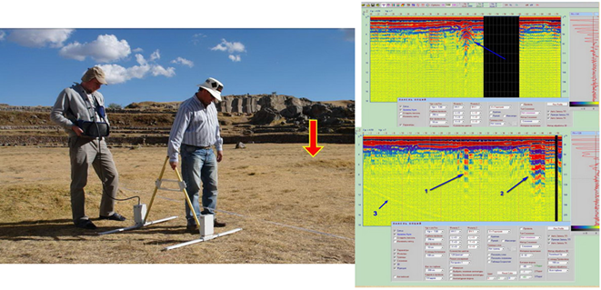
About 10 years ago, I came across a number of studies where a device was used that was able to see what was underground - georadar. For a week I could not tear myself away, I watched a huge amount of video materials, I remember the name of the device used by the researchers - the LOZA GPR. Below is an example of a study of Sacsayhuamana (Peru), where underground crypts, pits, a slab lying at a depth were found, and it can also be assumed that a bowl-shaped bottom was once filled up.
My first thought was, “Wow, that's cool! So you can find a lot of interesting things underground. And there is no other way! " This was the beginning of my interest in this device. It quickly became clear that it cost a couple of million rubles, that is, not everyone can afford it. I began to think how I could make such a device myself.
From the information on the Internet, I got an idea of how the device works. There is a Transmitter and a Receiver. The transmitter sends a very powerful, under several tens of kilovolts, nanosecond electromagnetic pulse deep into the earth.
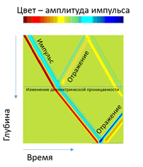
In those places where the dielectric constant of the medium changes, that is, the type of soil changes, its moisture content, or there is a foreign inclusion, an air cavity, part of this signal is reflected back. Another part of the signal goes further, deeper and is reflected from some next layer or object.
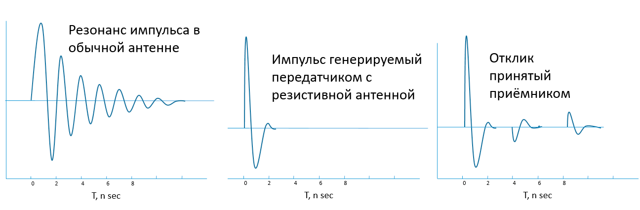
 Various sources have emphasized that so-called resistive (resist) antennas are used in GPR. These are special antennas that have no "ringing" - they do not resonate. A conventional antenna (Fig. 1) resonates (begins to be forced to vibrate) at its own operating frequency. Her own oscillations do not allow her to qualitatively perceive the useful signals that come at this time. The pulses sent by a resistive antenna differ from the classical radio pulse by the absence of a carrier frequency - asymmetric short pulses are obtained (Fig. 2). If a pulse is reflected from a medium with a higher dielectric constant, then it is inverted (Fig. 3). I began to figure out how to make such antennas.
The device itself also promised investments: “This device is so expensive, because there are probably expensive ultra-high-speed ADCs that allow very fast and high accuracy to measure the signal amplitude - this is already several thousand dollars; not to mention a powerful processor, ”I thought.
Imagine that powerful 10-kilovolt pulses of 1 nanosecond duration follow one another, bouncing repeatedly. The main task is to quickly digitize all information coming to the Receiver (convert from an analog signal to "understandable" to electronics, symbols possible for further processing - zeros and ones), analyze and record. And these are gigabytes of zeros and ones per second in a continuous stream.
“I am implementing this device on comparators for a start. Sheer pennies and multiple reductions in price ”- I decided. A comparator is a very basic electronic circuit whose sole purpose is to compare two incoming analog signals. It outputs 0 or 1 at the output, depending on which of the two incoming voltages is greater. That is, a comparator is a 1-bit analog-to-digital converter (ADC) that can record a binary waveform. However, to reconstruct the full amplitude of a single ground return pulse, hundreds of such comparisons with different comparator thresholds are needed. My super-budget solution could not boast of speed and efficiency.
In general, I slowly pondered the approaches to the implementation of the device until I met Vladimir Zubov and started seriously reverse engineering the DNA sequencer, about which I later published an article on habr.com . All this time, I continued to follow the GPR research with interest, but there was not enough time for everything. Imagine my surprise when a chain of random events led me to the same point from a completely different side.
 Three or four years ago I moved to live near Troitsk. Just then I published
an article about the sequencer, I was sitting there sorting out the incoming messages. Jonathan Rothberg himself
offered me a start-up, but something went wrong, there were many other time-consuming incoming messages - in general, I was completely immersed in the consequences of the publication. Not far from our house on the field there were huge antennas on masts (well, very healthy ones), we often went there with a quadrocopter. I became interested in them, began to google "big antennas, Troitsk", came across the site
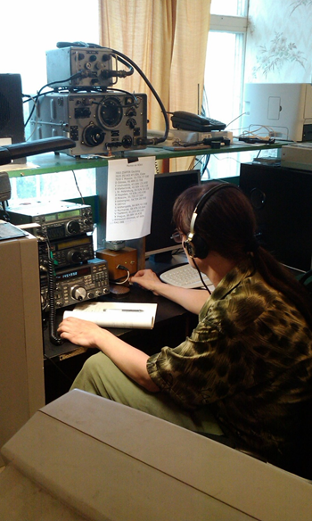
rk3b.ru with the intriguing name "School Space Communication Center", called there and asked to visit - the radio amateur himself.
Three or four years ago I moved to live near Troitsk. Just then I published
an article about the sequencer, I was sitting there sorting out the incoming messages. Jonathan Rothberg himself
offered me a start-up, but something went wrong, there were many other time-consuming incoming messages - in general, I was completely immersed in the consequences of the publication. Not far from our house on the field there were huge antennas on masts (well, very healthy ones), we often went there with a quadrocopter. I became interested in them, began to google "big antennas, Troitsk", came across the site
rk3b.ru with the intriguing name "School Space Communication Center", called there and asked to visit - the radio amateur himself.
 That is how I met Alexander Nikolaevich Zaitsev, the most honored person who headed this Center. It turned out that he had been studying the Earth's magnetosphere at IZMIRAN for many years and at the same time knew the entire scientific beau monde of Troitsk. We talked, I mentioned, among other things, about my interest in GPR. Alexander Nikolaevich, in turn, told me about the antennas on the field. They turned out to be purely amateur: the famous radio amateur V.N.Komarov, being at the same time a successful entrepreneur, gathered a team of HF communication enthusiasts, created a supercenter and such antennas with his own money that they became the best on the air. This is confirmed by the first places in the competitions for the HF World Championship.
And after a while A. Zaitsev introduced me to people from VNIISMI Company LLC, who (surprise! :) were engaged in the LOZA GPR. I met with P. Morozov and A. Berkut, who headed it. They gladly accepted me, and we got along in many ways. Imagine my amazement when they said that their device, the LOZA GPR, sold at a price of $ 25,000 in the basic configuration, works on comparators. And they just dreamed for a very long time to make a device on an analog-to-digital converter (ADC), which would allow the device to work quickly. And that the attempts were different, but they were not crowned with success. In general, they expressed their full interest in the development.
Subsequently, I received complete information on how the LOZA georadar works. There really was nothing but comparators and a few microcircuits, the best of which, however, was the most advanced in the FPGA family 20 years ago. The main complaint of VNIISMI about its device became clear: I was tired of pressing the button with my finger. After all, what is work on comparators: for one measurement (measurement at one point), 128 pulses must be sequentially sent to the ground, which takes from seconds to 2 minutes, depending on the transmitter. That is, the device works according to the principle: pressed the button, stood and waited, moved the device further along the tape measure by 10 cm (the tape measure is really spread on the ground to move in 10 cm increments), and so on. Can you imagine the speed of such work? By the way, the control unit or the computer is connected to the Transmitter with a wire,therefore, a minimum of 2 people are required for filming: the one who moves the georadar, and the operator following him on a wire.
 I also had the opportunity to study several different ground penetrating radars - serial devices and prototypes from different manufacturers and developers.
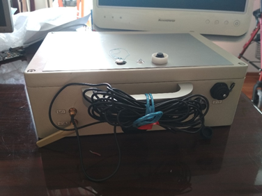
For example, this big heavy box weighs 5 kilograms or so; inside there is an ADC for 1800 Megasamples per second, each board in a separate case and with a separate screen - as a result, a lot of excess weight and large dimensions, which made the prototype impossible to use in principle; he did not work.
Another prototype was more successful, but the problem was that it took a very long time to set up; sometimes it did not turn on, it crashed. In general, one of the problems of a GPR is the need to operate in a very large dynamic range. The impulse that is sent underground, as it passes through it, very quickly decays. To see both the first response of this pulse and the response that came deep from the ground, you need amplifiers and ADCs that can receive and distinguish both very strong signals and very, very weak ones. This amplitude is called dynamic range. In this prototype, a two-channel amplifier was used for this - one amplifier channel worked with strong signals, and the other with weak ones. That is, there were 2 channels of digitization, which, by the way, could not be brought together in any way. By adjusting the gain,the device could be tuned to some depth and in it he saw something. But not higher, not lower than the specified level, he did not see until you reconfigure it to other parameters. In addition, the prototype had a very high sensitivity to interference.

So, I started to design my own high-speed, powerful device. The work was enormous, but there was good news: part of the work had already been done - as a basis I took the electronics that (ta-dam! .. :) I developed for the DNA sequencer.
The work on the GPR and the software package took about a year. I achieved not only full automation, high speeds, the ability to control the GPR from any device, I managed to create, in fact, a universal core for any high-tech project: system on a module (Zturn) → system on Zynq crystal → FPGA + CPU + Linux + Django + WebSockets + Javascript ... I'll leave the intrigue, though. In order not to tire the reader, I am putting out the technical part in a separate article.
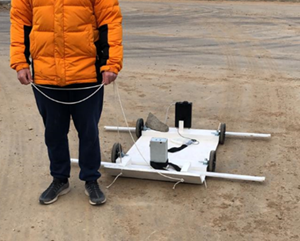
 The device I have developed consists of 2 devices - a Transmitter and a Receiver, each with its own antenna. Now the dimensions of the devices are 22.2 x 14.6 x 5.5 cm, in the next batch it is planned to further reduce the dimensions. For research at shallow depths, standard meter antennas are used. Depending on the length and power of the antennas, the sounding depth on favorable soils can reach several hundred meters. To move the GPR, a hand carrier, a platform on wheels, foldable / flexible deep-sensing antennas with seats for the Receiver and Transmitter can be used; for special tasks can be created by other means of movement (for example, inflatable - for the study of underwater objects).
A platform with a georadar can be attached to a vehicle, the georadar is capable of automatic surveying at speeds up to 40 km / h (what we tested is probably more). The movement of the device is recorded using a wheel sensor and GPS. All processes are automated, the device is easy to operate, does not require an additional operator, and one person can handle the shooting. Priorities: power, compactness, lightness, passive cooling, the possibility of completing with different means of movement and antennas of different power. These two small boxes can become the heart of a GPR complex of any power. Further boring, specification:
• Frequency range (MHz) 1-300
• 1000 ( 36 / 1 )
• : ,
• 5
• 1
• : 1GSPS (1)
• 16
•
• 120
• ( ) 16000
•
• 64
• : , ( ), GPS,
• wifi . web , PC
• 4 , (+12 )
•
• 222 146 55 mm ( 2)
• 100Mhz (1,5), 200MHz (1). 10MHz (10), 25Mhz (6), 50Mhz (3) ( , ). – . , / . , , 500 .

The georadar is ready to work immediately - after pressing the "ON" button, the georadar will begin to survey and record everything into the internal memory. It can work completely autonomously, without connecting an operator to it.
The device distributes wi-fi, you can connect to it from any computer, tablet, phone via a web browser. You are taken to a program that allows you to control the device, change settings, see the current track. The top line of the interface contains various statuses that make it possible to understand what is happening at the moment: battery voltage, temperature on the processor, time, operating time, GPS data. Below are tabs and buttons for setting triggers, offsets, logarithmic scale, zoom, operating modes.
The device can make one measurement by pressing a button, or by time, for example, every 0.3 seconds, or the measurements can be synchronized with the operation of the wheel, for example, every quarter of a wheel revolution is triggered, that is, the Transmitter sends a pulse, and the Receiver receives it and writes down. The latter mode is very convenient, as it allows you to bind the platform with the GPR to the machine, for example, and make uniform measurements regardless of the speed of movement.
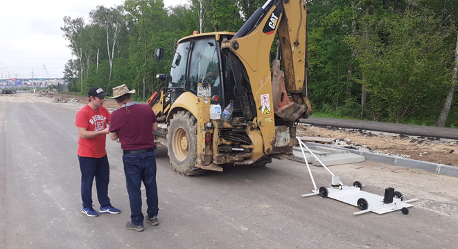
 The first launch was carried out together with representatives of VNIISMI on an asphalt road under construction in the south-west of Moscow. This is how the installation of my device looked like: 2 antennas on the platform as close to the ground as possible, the white box is the Transmitter, the black one is the Receiver.
 A place was chosen in advance where communications lay at different points underground. The plan was to determine such points first with the Loza device, and then look at the same place with my device. While VNIISMI was adjusting my device, I wound up half a turn and rode, and I saw everything. Here is the first picture from my device. We approached the workers who were building a road there at that time and checked the results of our surveys with the communication maps they had - everything coincided, there really were plastic pipes of 200 diameter at a depth of 2 m. It was a success.
The picture below shows a piece of the same footage of a road under construction. On the right, you see a wriggling bar - this is a pulse waveform. The small peak at the top is the pulse generated by the Transmitter, and everything below is what comes to the Receiver from all directions, but mostly from underground. The large color picture next to the pulse oscillogram is a set of such columns, that is, each pixel column is 1 pulse, only here the amplitude is converted to color. The red bar at the top of the color image is ground level. Further, the impulse goes into the ground, and below we see everything that is reflected and flew to the Receiver. The small blue-red bumps just below the second red stripe are the intersections of the antenna patterns with the pipe point objects. That is, in those places where, in the direction of movement of the device, we cross pipes,pipes give such a radio image, and in some places you can see two pipes if you zoom in.
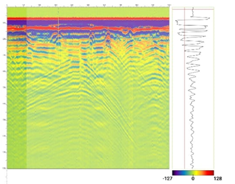 You can also see large blurry parabolas that go down to the end of the picture - this is a reflection along the air channel from various objects, in this case, power lines that stood nearby. In my opinion, this is a big problem that has not yet found a solution in the developments known to me. Information about reflections outside the investigated environment is clearly superfluous, it distracts attention and interferes with the interpretation of the useful signal, since it is constantly necessary to analyze the environment and decide whether this reflection came from underground or through the air. Therefore, it is planned to use software and hardware to minimize reflections in the air.
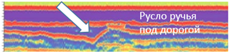 Here in this picture - a stream, buried during the construction of the road; the channel can be seen at a depth of about 2 meters. Below in this section there were also large parabolas - reflections from the lighting poles along the road.
Near my house there is a river Neznayka with a very interesting geology, where everything is like in a textbook: there is an old river bed, Quaternary deposits, alluvium, river terraces. There, too, we went with the guys from VNIISMI, tested, compared the work of different georadars. Here, at the end, you can see the old river bed, and the large green parabolas are the reflection of the fence of the neighboring village on metal posts.
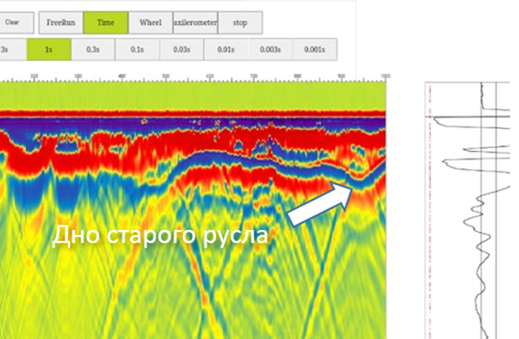 As you can see, only a person who is already familiar with the principles of interpreting such pictures will immediately determine that this is a river bed, and this is a reflection from a fence. Thus, the very form of data output significantly limits the circle of people who can easily start working with GPR. And here, in my opinion, there is a very interesting task - to translate this data into a picture that any user can understand. This task can be accomplished using artificial intelligence (neural networks), which can be trained to mark, designate the real contours of objects and assume their purpose and properties. Volumetric constructions will also help to solve the problem of unreadable data, but more on that later.
The picture below shows a very interesting relief (filmed on July 22, 2020 in the Ivanovo region, Kalinkino village): some kind of oblong structure is visible - most likely it is a layer of sand or some other less dense than the loam and soil prevailing in our area. I have an idea to fully automate the identification of layers. As we defined above, the wave is reflected from those places where there is a change in the dielectric constant of the medium. We can measure the speed of the pulse on one or another layer of this picture and assume the composition of the environment and / or the degree of its humidity.

At the end of the summer, I managed to go on an archaeological expedition near Ryazan near the village of Terekhovo, Shilovsky district, to the site of a fifth century camp / settlement. There, at the convergence of two rivers, there is a hill overgrown with trees - there are numerous evidences that in the fifth century there was a Settlement. We began to walk there with a georadar - in the first picture, our GPS track. Trees grew very densely in the center, we were able to walk along the perimeter, there were fewer trees further, and we all walked quite densely. I had the opportunity to use a program that was announced as a program that allows you to build a 3D model from linear penetrations. Archeologists expected such a result from me - “we will build and see clearly what is buried where”. It is best to make such constructions from well (densely) groomed areas.I loaded the area with the densest passes into the program and entered 3D mode - the program built a field of color bars that could be "pulled" up and down, changing the settings, I did not see any more possibilities - after consulting, I found out that the program builds only pseudo 3D.
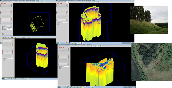
Let's imagine that we have some columns that we know, where the ground penetrating radar has traveled from above, and we know that it is vertically down at this point. The next task is to complete the missing columns by approximation, which is what the program did. But she did it corny with a grid along 2 axes. As a result of this construction, various artifacts arise - cruciform, from horizontal and vertical lines. If we take a slice of a 3D plane, we have a color image from a slice of columns, which the program simply pulls up or down, depending on the signal amplitude.

Real 3D construction is somewhat more complicated - from points physically filmed at different depths, we need to identify certain planes, transition planes from one to another and then, using the user interface, be able to select individual planes that we need to display.
Building a volumetric model is generally a separate very interesting task. Now I am thinking about the idea of using one antenna with a Transmitter and 2 antennas with Receivers that are spaced apart from each other, that is, 2 Receivers. It turns out a kind of phased array antenna. By the time the signal travels, more precisely by the difference in the time it was received by the first and second Receivers, you can determine the exact place where this signal was reflected. Thus, in one measurement, measuring a single pulse, we can immediately build a picture in a 2D plane. Conventional radar uses carrier frequencies, Fourier transforms, sine and cosine plotting. In this case, some excellent math is used:Based on the data on the reflection of a single nanosecond pulse, we make a convolution and then calculate where this pulse came from with what probability. This idea is now in the stage of writing software, which will allow immediately during the passage to simulate a 3D picture, as well as measure the speed of passage of a pulse in layers, which will allow us to immediately assume the composition and quality of the media.
Where can GPR be used?
The uppermost layers under the surface of the earth are called the "cultural layer" - this is archeology, individual objects, foundations of buildings are perfectly visible, even dug and once pits are visible. So, there is a very interesting problem associated, for example, with the Sahara Desert. The Sahara is expanding, and many archaeologists agree that cities and buildings are buried under its sands. In the days of Egypt, there was a savannah, rivers flowed, animals lived. GPR can scan everything to the ground and find buildings and settlements there. This is actually the only device that is able to do this.
By the way, the scanning depth depends on the density and type of soil, its mineralization and moisture content. Sand is the soil in which the GPR sees the deepest. The second such medium, which is very permeable to GPR, is ice. So, GPR can be used for subsurface sounding of water bodies. In salt water the depth of sounding will be shallower, in fresh water it will be deeper, and the deepest sounding can be done in ice.
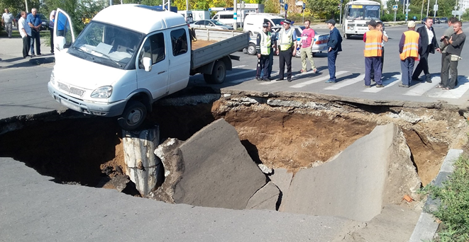
Another application of GPR is searching for underground utilities, pipes, passages, tunnels. The quality of road construction can be very effectively controlled - how thick the sand substrate was laid, whether the asphalt was evenly laid. You can also check the condition of the foundations and walls of buildings. It is possible to monitor the condition of the roadway during operation in order to take timely measures in case of road undermining, the formation of karst cavities, while this has not yet led to a failure. Erosion occurs under the foundations of buildings and structures. So, the reason for the oil spill in Norilsk was that the foundation of the oil storage was undermined. Regular checks of such objects would help to successfully prevent such disasters.
Geology. During georadar surveys, the boundaries of rivers, limestone outcrops, where which layers of rocks are located, are clearly visible, kimberlite pipes, moraines. By indirect indicators, groundwater can be determined. So, water seeps down until it meets some layer through which it cannot seep, and accumulates at the border of the layers in the lowland. It is also possible to predict and prevent mudflows, landslides. GPR can be useful in mineral exploration, including drilling.
In December 2020, the basic version of the device was successfully tested and certified. The ground penetrating radar was named GEORA.
The first small batch is being prepared for release. The goal is to start gaining a wider experience of practical use and, based on this experience, identify opportunities to improve the usability and functionality. The second task is to create next generation software that will make data analysis visual and convenient even for an unprepared user.
Two versions are planned for wide release: for private use and for commercial. It is possible to customize equipment and software for any task.
The global goal is to make georadar a more massive thing, affordable for a person interested in history and archeology. Available to individual entrepreneurs who work in the field of design, construction, expertise, subsoil research. The widespread adoption of the instrument will form a community of users. The plans are to create a centralized measurement database. So that anyone, if desired, can send scanned data to the server, share them on a reimbursable or free basis. In addition, a larger data array will make it possible to more effectively train the neural network to interpret the scan results and visualization that is understandable to an ordinary person.
Now the second part of the article with a detailed description of the technical part is being prepared for publication. That's all for today, if you're interested - write, mail sokolov.labs@gmail.com . Bye everyone, thank you for your attention!