Paradigm
It is quite important to emphasize here that the machine code should look, in a relatively fluent subjective perception, as a pseudocode in the fields of the dump tables and, as little as possible, give the esotericity of any bit fields.
Command Decoder
One of the most important and key elements of any automaton is a device for decoding exactly that action at a certain moment in time that the programmer himself had in mind when he composed the order of these commands in his algorithms.
First, it is necessary to make a sketch of the Koda-Koyaaniskatsi decoder in Logisim , using the most accessible logic gates from the nomenclature of the TTL series being produced, in order to ensure easy assembly of the decoder on real microcircuits.
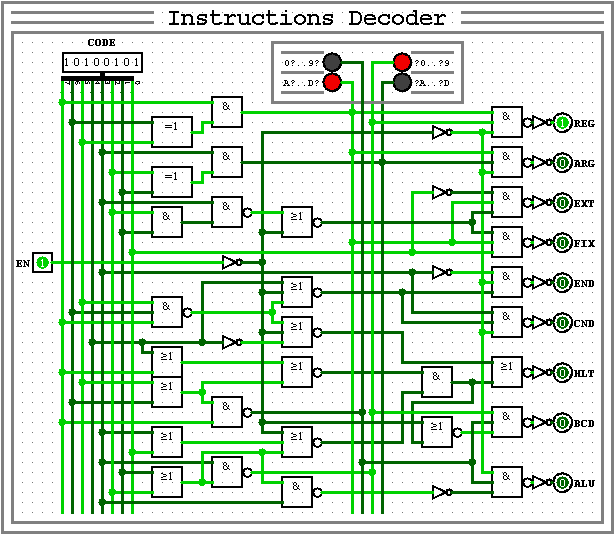
Here we come up with a Conditional Graphic Designation for the decoder, which is necessary to ensure the compactness and clarity of the whole circuit of the machine in the future, as well as to check the correct operation of the decoding of all 256 instruction codes.
Timeless Prefix Registers
When the visual testing of the decoder's performance went well and without visible failures, it was time to connect the main registers for storing the indices of active RONs, which are triggered by the commands of the REG group as architectural prefixes.
To ensure the storage of vectors of data routing by ALU and RAM instructions, one more register and two linked multiplexers are added, with which you can link arbitrary registers of any groups as instruction operands.

By themselves, these registers are not intended to store the results of calculations and play a kind of role as pointers to the required registers in order to provide a controlled interaction in the program between all available RON and / or memory.
Architectural Condition
Ensuring the normal program interaction of all registers requires the presence of a two-port Register File, which is not included in the Logisim libraries, forcing us to look for other more or less costly alternative solutions. The classic Koyaaniskatsi has a rather complex Register File, which is not considered here as an illustrative example and requires the development of a new solution for organizing a multi-cycle Register File with slow access. Since the scheme turned out to be one-cycle, it is quite difficult to organize the Register File in RAM here and it becomes necessary to build a multi-cycle scheme with many special cycles replacing each other in a strictly specified order.
The algorithmic expression of the cycle counter can be described as "m & = m - 1" with sequential switching off of all active bits of the architectural state, where at a certain moment of the Machine Cycle only key nodes of the circuit are activated.
The maximally expanded prototype of the Machine Cycle Counter can be represented on a sketch of a similar circuit, which is quite difficult to understand the logic of its operation.
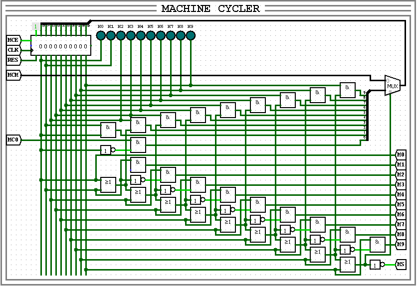
A similar sketch can serve as the most optimal and universal option:
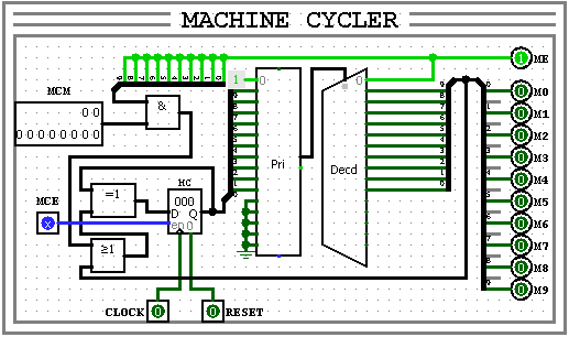
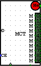
And for use in the schema, the Conditional Graphic Designation can be as follows:
With the help of 3-OR logic gates, it is now possible to translate the signal of each of the commands into the bit mask of the necessary cycles necessary for the correct execution of the command, for the entire period of execution of which the command counter will be temporarily suspended.

Conclusion
So, as you can see, in order to at least more or less begin to understand the nuances of self-construction of a programmable machine, we just need to get by with even basic knowledge at the levels of drawing a blinking Christmas tree garland circuit. No reference materials known to everyone were deliberately used here, so that the creative process was more exciting and free from any global trends and trends, not paying attention to all possible miscalculations or mistakes.
In the next part I will try to continue my step-by-step construction of the "akyn processor",
since the new draft is almost working for me, but I decided to redraw it from scratch,
and at the same time document all the key stages ...