In this article I will try to outline the essence of my project and show the process that flowed from a sketch of a robot dog into ordering printed circuit boards for a glove
Start
The glove is straight out of my Mark project and is also a significant part of it, so you should start with it.
The very first prototype of the robot was made one evening in the summer of 2018. It was a four-legged robot made up of 8 SG90 servos (regular blue) and pieces of nails. All this was connected with hot melt glue and did not have a single chance for normal operation due to the very poor distribution of mass. But I did not know this, and that evening I forced him to walk in a straight line, and another 15 minutes after that, the board through which the power was supplied began to smoke and a sealed linear stabilizer appeared on the table (by the way, I did not understand what happened there) ...
I could not fix this pile of hot glue nails and electrical tape. In my defense, I can say that at that moment I did not know how to solder, from electronics I only understood that it was impossible to close + and -, but I had not heard about the existence of 3D printing.
At the end of summer I ordered my first printer - Anet A8.
Ordinary printer to familiarize yourself with the technology: an acrylic frame, kinematics with "drywall" and noisy motors (rather their drivers)
Almost immediately after buying it, I mastered tinkercad, where I recreated that robot on 4 legs, already with replacing the nails with plastic and adding a rotary servo.
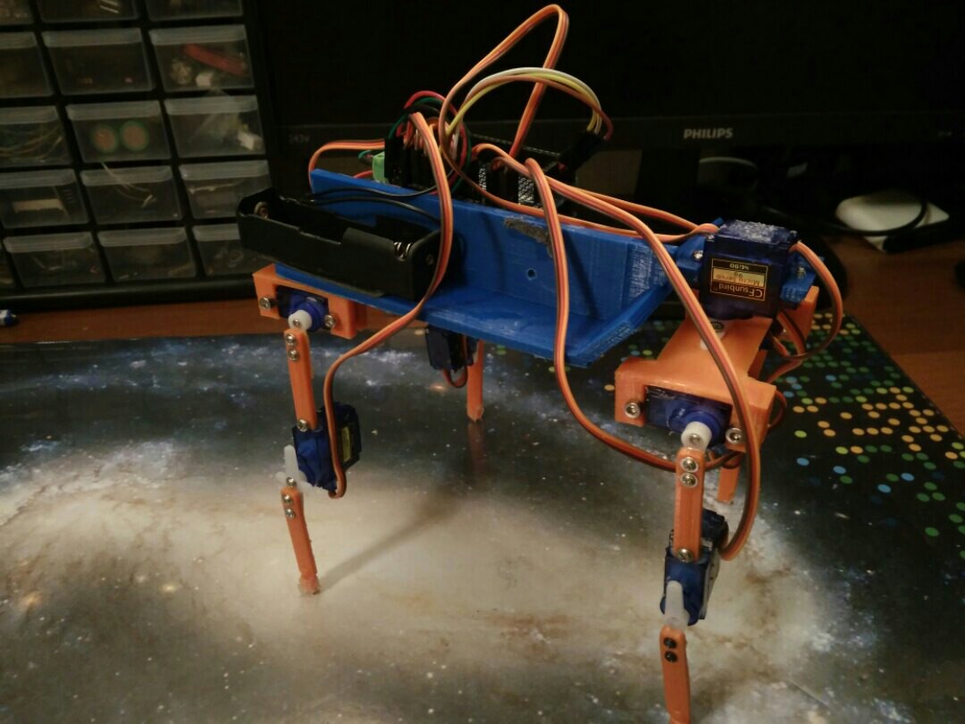
This creation never came, but it encouraged me to create other versions. Maybe I'll make a separate article for my worm-footed robots, so I'll just give you a sequence of photos of the versions.
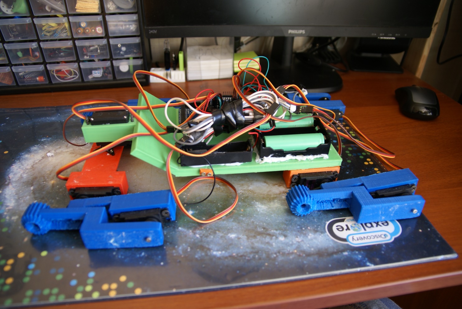
The latest version is now acquiring a body, but it walked normally and has a good carrying capacity.
2 Mark. , . - , .
:
Mark - , - .
Mark 6 - , .
Mark 3 - , , 4 .
Mark 4 - , .
Mark 5 - 6 . .
Mark 7 - , Mark 5 .
Mark gauntlet – .
Mark 6, Mark 4, Mark 3 Mark gauntlet.
Mark 6 ,
: 1
2020 , : 433 . ( , ) https://youtu.be/eEAHhr9Suug?t=194
: 2
2 , .
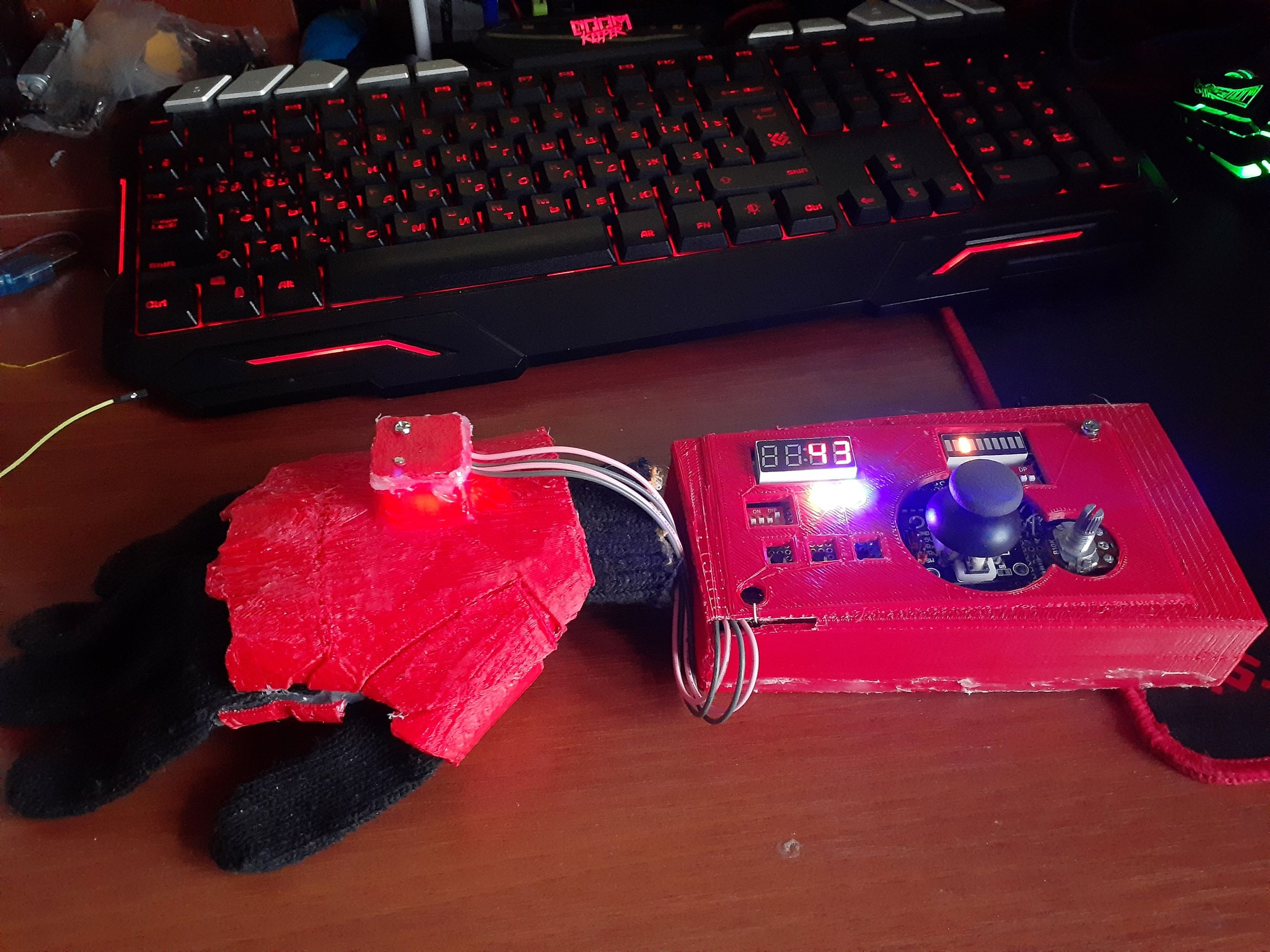
nrf24l01, . https://youtu.be/P_fq7KkfJrI
Rukami. 2-3 , .
: 3 4
.
3 :
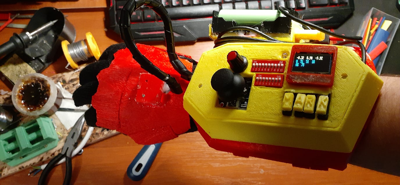
:
WiFi esp8266
NRF24l01+
433
Bluetooth
+
OLED
, - . https://youtu.be/52WvejA6dyk .
4 :
Atmega2560
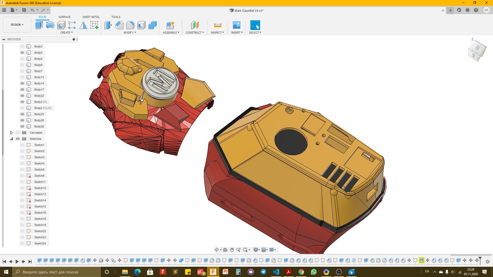
:
:
WiFi
NRF24L01+
LoRa
MP3
- ( )
+
+
OLED
, 4.2
4.2
, ,
-
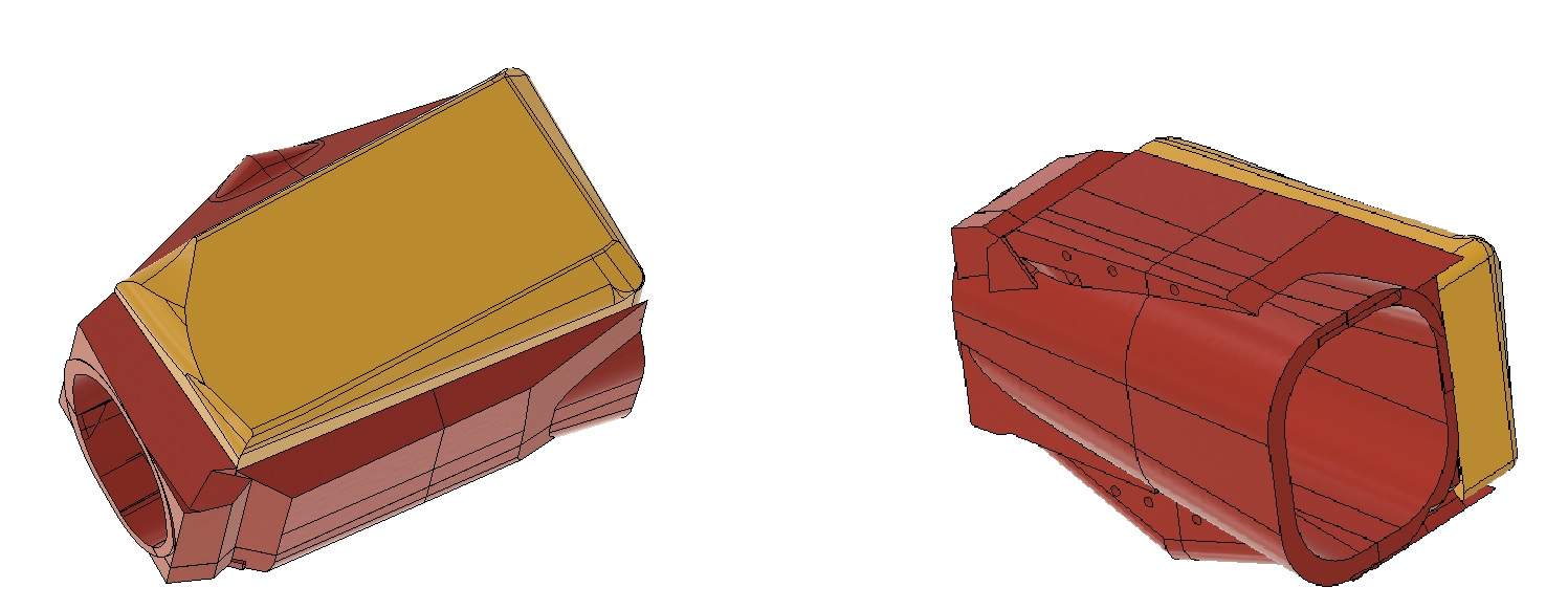
4
3 18650 3.4 * , . .
2 ,

, . LoRa . : https://github.com/Madjogger1202/Mark_GauntletV4.2/blob/main/src/main.cpp
.
/*
Hi stranger, this is main code file for this project
I'm not a 100% programmer, but i can make electronics work,
so i will be grateful if you add any features
it is fully opensource project, so anyone can build stuff based on this code
have a great time reading this badly written working code (^_^)
*/
#include <Arduino.h> // why not...
#include <Wire.h>
#include <SPI.h>
// i have to make all modules work, so i will use some libraris to make life easier
//1) Display. im using 0.96 oled from china, it is not standart at dimentions, bt i like how it looks in final designs :)
#include <Adafruit_GFX.h>
#include <Adafruit_SSD1306.h> // Adafruit librari works 50/50, it depends on display driver (yes, they can hava same names, bt diffrent drivers)
//2) RGB Led panel. LEDs 2812 (8-bit panel)
#include <microLED.h>
//3) NRF24L01+
#include <nRF24L01.h>
#include <RF24.h>
//4)APDC9960 usefull sensor
#include "Adafruit_APDS9960.h"
//5) LoRa radio sx1278
#include <RH_RF95.h>
//6) MPU6050 gyro + acsel
#include <Adafruit_Sensor.h>
#include <Adafruit_MPU6050.h>
//7) MP3 module
#include <DFPlayer_Mini_Mp3.h>
// first switches connection
int8_t first_sw[8] = { A14, A13, A12, A11, A10, A9, A8, A7 };
// second switches connection
int8_t second_sw[8] = { 38, 37, 36, 35, 34, A6, 32, A15 };
// buttons connection
int8_t buttons[4] = { A3, A1, A0, A2 };
#define LED1 10
#define LED2 11
#define JOY_X A6
#define JOY_Y A5
#define POT A4
#define LORA_D0 42
#define LORA_NSS 43
#define LORA_RST 44
#define NRF_CSN 40
#define NRF_CE 41
#define IR_LED 7
#define R_LED 4
#define G_LED 5
#define B_LED 6
#define WS_LED 45
LEDdata leds[8];
microLED strip(leds, 8, WS_LED);
#define ORDER_GRB
RF24 radio(NRF_CE, NRF_CSN);
Adafruit_MPU6050 mpu;
Adafruit_SSD1306 display(128, 32, &Wire, -1);
Adafruit_APDS9960 apds;
volatile bool irqMPU;
volatile bool irqAPDC;
struct allData
{
volatile boolean irqMPU;
volatile boolean irqAPDC;
bool stable;
int8_t x_acs;
int8_t y_acs;
int8_t z_acs;
uint8_t mode;
uint8_t channel;
uint16_t button;
uint16_t potData;
uint16_t joyX;
uint16_t joyY;
uint8_t led1Mode;
uint8_t led2Mode;
uint8_t redLedMode;
uint8_t blueLedMode;
uint8_t greenLedMode;
uint8_t wsLedMode;
}mainData;
struct radioData
{
bool stable;
int8_t x_acs;
int8_t y_acs;
int8_t z_acs;
uint8_t mode;
uint8_t channel;
uint16_t button;
uint16_t potData;
uint16_t joyX;
uint16_t joyY;
} telemetriData;
void readMode();
void readCh();
void readAcs();
void readJoy();
void readPot();
void readButtons();
void sendNRF();
void sendBL();
void sendLoRa(); // will reliase it soon
void displayInfo();
// at all it is possible to create up to 256 diffrent modes,
// but if you need more - connect mode counter with channel counter (maybe partly)
void n1Mode();
void n2Mode();
void n3Mode();
void n4Mode();
void n5Mode();
void n6Mode();
void n7Mode();
void n8Mode();
void n9Mode();
void n10Mode();
void n11Mode();
void n12Mode();
void acsel()
{
mainData.irqMPU=true;
}
void gesture()
{
mainData.irqAPDC=true;
}
void setup()
{
for(int i=0;i<8;i++)
pinMode(first_sw[i], INPUT_PULLUP);
for(int i=0;i<8;i++)
pinMode(second_sw[i], INPUT_PULLUP);
for(int i=0;i<4;i++)
pinMode(buttons[i], INPUT_PULLUP);
pinMode(LED1, OUTPUT);
pinMode(LED2, OUTPUT);
analogWrite(LED1, 10);
analogWrite(LED2, 100);
pinMode(JOY_X, INPUT);
pinMode(JOY_Y, INPUT);
pinMode(POT, INPUT_PULLUP);
pinMode(LORA_D0, OUTPUT);
pinMode(LORA_NSS, OUTPUT);
pinMode(LORA_RST, OUTPUT);
pinMode(NRF_CSN, OUTPUT);
pinMode(NRF_CE, OUTPUT);
pinMode(IR_LED, OUTPUT);
pinMode(R_LED, OUTPUT);
pinMode(G_LED, OUTPUT);
pinMode(B_LED, OUTPUT);
pinMode(WS_LED, OUTPUT);
strip.setBrightness(130);
strip.clear();
strip.show();
strip.fill(mCOLOR(YELLOW));
strip.show();
Serial.begin(115200);
Serial2.begin(9600);
mp3_set_serial(Serial2);
mp3_set_volume(30);
mp3_play (1);
if (!mpu.begin())
Serial.println("Sensor init failed");
if(!display.begin(SSD1306_SWITCHCAPVCC, 0x3C)) { // Address 0x3C for 128x32
Serial.println(F("SSD1306 allocation failed"));
for(;;); // Don't proceed, loop forever
}
display.display();
display.clearDisplay();
display.display();
if(!apds.begin())
Serial.println("failed to initialize device! Please check your wiring.");
apds.enableProximity(true);
apds.enableGesture(true);
radio.begin();
radio.setChannel(100);
radio.setDataRate (RF24_1MBPS);
radio.setPALevel (RF24_PA_HIGH);
radio.openWritingPipe (0x1234567899LL);
radio.setAutoAck(false);
attachInterrupt(0, acsel, RISING);
attachInterrupt(1, gesture, RISING);
Serial1.begin(9600); // bluetooth module connected to Serial1
delay(5000);
mp3_stop ();
}
void loop()
{
readMode();
readCh();
readAcs();
readJoy();
readPot();
readButtons();
Serial.println(digitalRead(A14));
Serial.println(digitalRead(A13));
Serial.println(digitalRead(A12));
Serial.println(digitalRead(A11));
Serial.println(digitalRead(A10));
Serial.println(digitalRead(A9));
Serial.println(digitalRead(A8));
Serial.println(digitalRead(A7));
Serial.println();
Serial.println();
displayInfo();
switch (mainData.mode)
{
case 0:
n1Mode();
break;
case 2:
n2Mode();
break;
case 3:
n3Mode();
break;
case 4:
n4Mode();
break;
}
}
void readAcs() // reading acseleration values from sensor directly to main struct
{
sensors_event_t a, g, temp;
mpu.getEvent(&a, &g, &temp);
mainData.x_acs = a.acceleration.x;
mainData.y_acs = a.acceleration.y;
mainData.z_acs = a.acceleration.z;
return;
}
void readJoy() // i am filering analog values for better perfomance
{
mainData.joyX = (analogRead(JOY_X)+analogRead(JOY_X)+analogRead(JOY_X)+analogRead(JOY_X))/4;
mainData.joyY = (analogRead(JOY_Y)+analogRead(JOY_Y)+analogRead(JOY_Y)+analogRead(JOY_Y))/4;
return;
}
void readPot()
{
mainData.potData = analogRead(POT);
return;
}
void readButtons() // buttons : 1) 1; 2)0; 3)1; 4)1; and mainData.button == 1011
{
mainData.button = !digitalRead(A1)*1000+!digitalRead(A2)*100+!digitalRead(A3)*10+!digitalRead(A0);
return;
}
void sendNRF()
{
// i am writing telemetri struct only when sending data
// in this case i can track how relevant telemetri data is
telemetriData.stable = mainData.stable;
telemetriData.x_acs = mainData.x_acs;
telemetriData.y_acs = mainData.y_acs;
telemetriData.z_acs = mainData.z_acs;
telemetriData.mode = mainData.mode;
telemetriData.channel = mainData.channel;
telemetriData.button = mainData.button;
telemetriData.potData = mainData.potData;
telemetriData.joyX = mainData.joyX;
telemetriData.joyY = mainData.joyY;
radio.write(&telemetriData, sizeof(telemetriData));
}
void sendBL(String inp)
{
Serial1.print(inp);
return;
}
// void sendLoRa();
void displayInfo()
{
display.clearDisplay();
display.setTextSize(1);
display.setTextColor(WHITE);
display.setCursor(0, 0);
display.print(mainData.channel);
display.print(" ");
display.print(mainData.mode);
display.print(" ");
display.println(mainData.z_acs);
display.print(mainData.button);
display.print(" ");
display.print(mainData.joyX);
display.print(" ");
display.print(mainData.joyX);
display.print(" ");
display.println(mainData.potData);
display.display();
}
void readMode()
{
bitWrite(mainData.mode, 0, (!digitalRead(A14)));
bitWrite(mainData.mode, 1, (!digitalRead(A13)));
bitWrite(mainData.mode, 2, (!digitalRead(A12)));
bitWrite(mainData.mode, 3, (!digitalRead(A11)));
bitWrite(mainData.mode, 4, (!digitalRead(A10)));
bitWrite(mainData.mode, 5, (!digitalRead(A9)));
bitWrite(mainData.mode, 6, (!digitalRead(A8)));
bitWrite(mainData.mode, 7, (!digitalRead(A7)));
return;
}
void readCh()
{
bitWrite(mainData.channel, 0, digitalRead(second_sw[0]));
bitWrite(mainData.channel, 1, digitalRead(second_sw[1]));
bitWrite(mainData.channel, 2, digitalRead(second_sw[2]));
bitWrite(mainData.channel, 3, digitalRead(second_sw[3]));
bitWrite(mainData.channel, 4, digitalRead(second_sw[4]));
bitWrite(mainData.channel, 5, digitalRead(second_sw[5]));
bitWrite(mainData.channel, 6, digitalRead(second_sw[6]));
bitWrite(mainData.channel, 7, digitalRead(second_sw[7]));
return;
}
void n1Mode()
{
sendNRF();
digitalWrite(LED1, !digitalRead(LED1)); // just blink to understand, that it is working
}
void n2Mode()
{
}
void n3Mode()
{
}
void n4Mode()
{
}
void n5Mode()
{
}
void n6Mode()
{
}
void n7Mode()
{
}
void n8Mode()
{
}
void n9Mode()
{
}
void n10Mode()
{
}
void n11Mode()
{
}
void n12Mode()
{
}