Part 1. Components Used
A few years ago, on the vastness of the network, I saw an interesting project in which the author made a huge digital clock (with 7-segment numbers), which is based on the so-called addressable LED strip.
Photo of the finished project
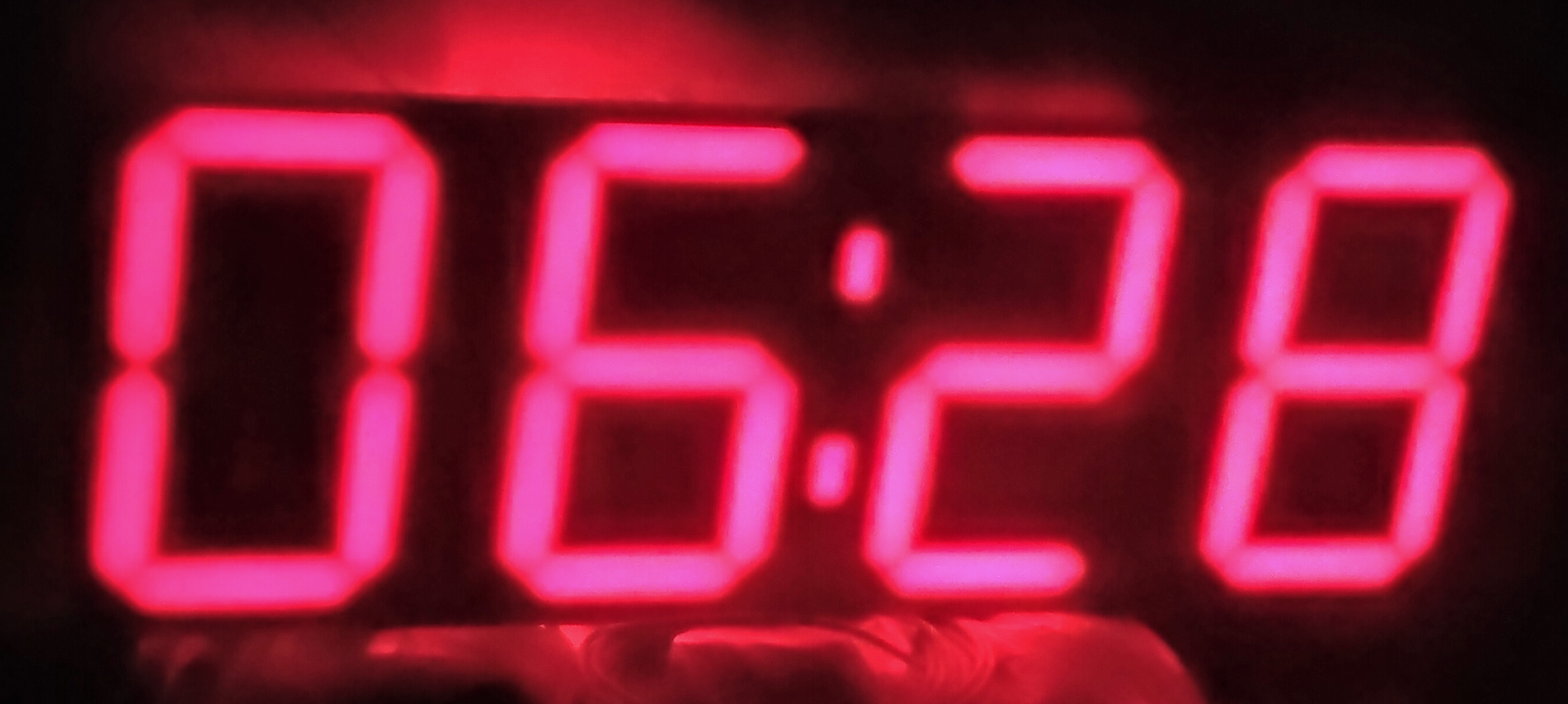
I used a figure size of about 280x205 mm (almost A4 sheet), the total size of the watch is 300x800 mm.
This project was repeated many times, each time in different ways, but I have not come across a clear guide for assembling these watches, and in addition, I will try to describe in as much detail as possible the features and difficulties that I had to face. In addition, this watch has been working for me for about 3 years, and quite recently I updated both software and hardware, looking back at the experience of their use, in connection with which I will tell you about some of the technical improvements that I applied in this project.
What is Addressable LED Strip
A common RGB LED strip has 4 pins: common "+" and 3 "-", respectively, for each of the primary colors - red, green and blue.
, : .
: , ( ) , , . 3 : "+", "-" , .
2 , :
WS2811. ( "" WS2812b). 3 .
WS2812b. Used by me (considered unreliable, although no problems were identified during the use of the watch). Allows you to control each diode separately. Of the minuses - if 1 diode fails - further ones will not work.
WS2813, WS2815, WS2815 - WS2812 update, have "backup" data transfer contact, increased update frequency. If one diode fails, the rest of the tape segment remains operational. Cons - price.
You can read more about ribbons and the peculiarities of their connection here.
So, we need:
:
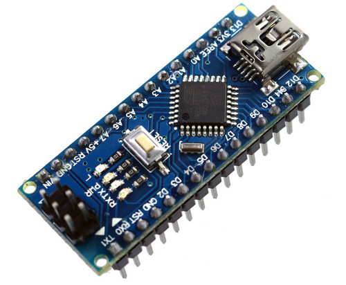
Arduino Nano ( ATmega328) - , . "", . "", , , .
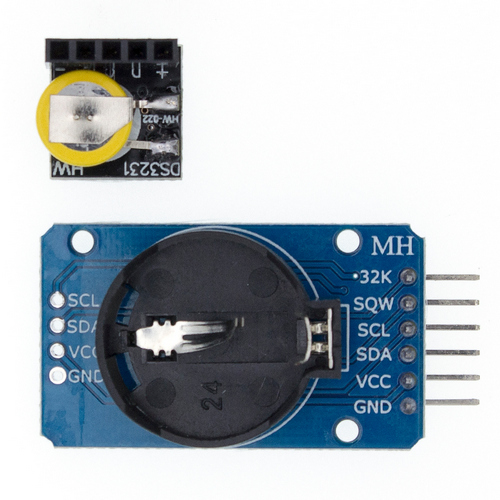
DS3231, , .
DS1302 DS1307 , .
: () (). , .
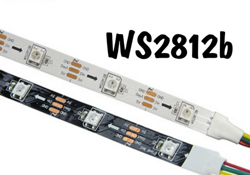
. .
WS2812b 60 .
WS2811 ( , , 12V , WS2812b 5V).
30 , , .
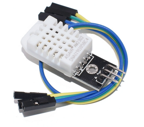
( - / ).
DHT22 (, ) - , " " DHT11, , , , .
( ).
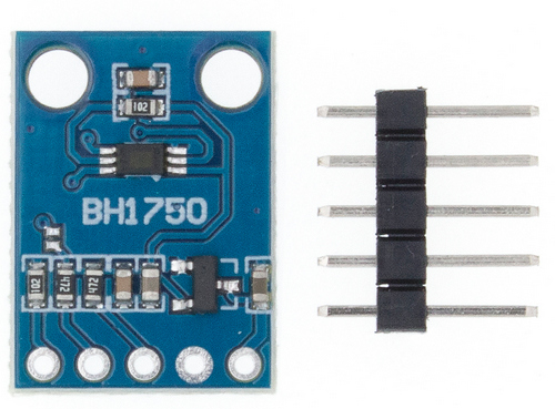
BH1750 :
1. ( , "/").
2. ( ), , " " ( ).
bluetooth
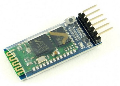
, , , bluetooth (, ).
, 3,5 , - .
- HC-05 HC-06, "".
10 (5V/2A), (172 ), , .
?
12 . , 60 / , (12*3*60) 2.1A.
, ; .
: WS2811 12V, WS2812b - 5V.
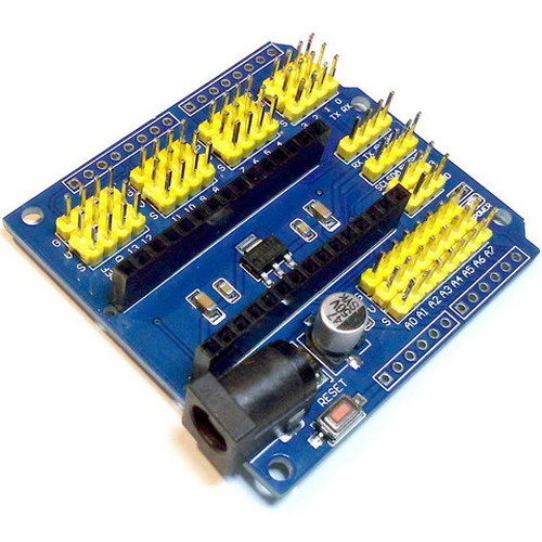
, , .
, , .
, .
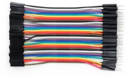
- ( ). ("-", "-", "-").
.
("") - "", , - .
, "" . (opal). - , . 4 , , ( "" ).
As I understand it, polycarbonate can be ordinary, also white (milky).
It is preferable to use "opal", as it is specially made to diffuse light and has two different sides: one directed towards the light source, the other outward, towards the viewer.
Since there is a lot of material, by the end of writing this part, I thought it would be correct to divide the article into parts.
In the next part I will talk about the assembly of components, and I will most likely leave the analysis of the software part for the third part.
