Benchmark for manipulation technology
The benchmark is designed to assess the effectiveness of the use of a robotic complex (RTC) in the tasks of manipulating objects in comparison with the use of manual human labor.
The benchmark contains the following set of metrics (coefficients):
ω a K a - weighted coefficient of autonomy,
ω l K l - weighted coefficient of learning time to complete the task,
ω w K w - weighted coefficient of carrying capacity,
ω c K cIs the weighted coefficient of collision of the working scene,
ω d K d is the weighted coefficient of difficult working conditions,
ω p K p is the weighted coefficient of rejects,
ω o K o is the weighted coefficient of the average daily rate of atomic operation,
ω e K e is the weighted coefficient of entropy.
Generalized formula for calculating the benchmark:
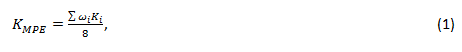
Where ω i K i- a weighted coefficient from a set of metrics.
Each metric considers the characteristic of the use of a robotic complex in relation to a similar characteristic in the case of manual labor and is dimensionless. The meaning of each metric is interpreted in relation to the person:
- if the value is less than one, then the use of the RTK for the measured task is less effective than using human labor.
- if more than one, then the use of RTK is more effective in relation to the use of manual labor.
The generalized estimate calculated by formula (1) is interpreted in the same way, and for the value of each metric K i its weight ω i is determined , which denotes the contribution of the metric to the overall result.
The weight of a metric is determined by the degree of its criticality for performing individual tasks, and by default the weight of the coefficients is the same (equal to 1).
In the case of comparing the RTK with a machine gun or another RTK, the benchmark value is calculated for them separately in relation to a person and compared. A more efficient RTK will receive a higher benchmark value.
Robot autonomy coefficient
This metric is used to assess the additional costs of human participation in the system. The value of the coefficient is in the range [0 ... 1], where 0 - the resulting system is not autonomous, maintenance requires the constant presence of personnel, 1 - the resulting system is completely autonomous, does not require maintenance personnel.
Mathematical model of the metric
To determine the coefficient of autonomy, it is proposed to use the probability of the robot's transition to a state that requires interaction with the operator.
It is proposed to divide the classes of states into several groups:
- e - States directly related to the manipulator and its software.
- c - States associated with client equipment.
- f – , .
For each of the class of states, it is proposed to introduce the probability of the system transition to this state as the ratio of the number of observations of each class of events to the total number of operations performed according to the formula:

Where p i is the probability of the i class of events (e, c, f), n i is the number of events i class, n a - the number of operations performed by the robot. Under n a it is proposed to use the number of atomic operations of the robot that affect the environment.
To determine the coefficient of autonomy, it is proposed to use the following formula:

Where p e , p c, p f - probabilities of events of classes (e, c, f).
To estimate the proportion of the time spent on servicing the robot, it is proposed to introduce the following metric:

Where p i is the probability of the origin of the i class of events, n o is the number of atomic operations of the robot per shift t i is the normalized time to eliminate the robot's withdrawal from the state requiring external intervention. Then the ratio

Where t sh is the shift time can be used to calculate the number of operators to the number of robots.
Coefficient of learning time for a new task
, . [0, +∞), 0 , , 1 , , , 2 , , .
A person learns for a certain amount of time. For complex tasks it can be months, for simple tasks it can be hours and minutes. To calculate the coefficient of the training time for a new task, a metric is proposed

where t h is the training time for a person to a new task, t rai is the training time for an intelligent robot agent in a new task.
The parameter t rai is calculated as:

Where t mh is the labor intensity of the processes necessary for training the intelligent robot agent, including but not limited to:
- The time to build the scene in which the system is running, including the integration time of the capture model, in the case of using a specialized capture.
- The preparation time for the trajectory planner to work in the scene.
- The time Ai learns to solve the problem.
The t hum parameter consists of a set of human training actions.

Where t int is the time of the plan for putting a person to work (initial instruction of the employee), t hi is the time i of the training program during the period necessary for training a person when receiving a new task, which include, n yi is the number of times per year, n s - the number of trained employees.
Robot-to-person lifting capacity
. (0...+∞), 0 – , 1 – , 2 – .
To determine the coefficient of the lifting capacity of a robot to a person, it is proposed to use the following formula:

Where k r is the lifting capacity of the robot, k h is the lifting capacity of a person.
To determine the carrying capacity of the robot, it is proposed to use the formula:

where mi is the transferred mass during the time t, n is the number of carried loads.
To determine the coefficient of the carrying capacity of a person, one must be guided by the legislation of the Russian Federation, in particular [1]. Taking into account the presence of the maximum permissible weight permissible for lifting by a man, it is proposed to use the following formula:

Where m iIs the transferred mass during the time t, n is the number of transported loads, k l is the multiplier taking into account the standard load for 1 person, which is calculated as

Where k m is the coefficient depending on the maximum weight of the object carried by the person per unit of time, k A is the coefficient dynamic work performed by a person per shift. To calculate the coefficient k m, it is proposed to use the following formula:

Where m norm is the mass permissible according to the work standards, m i is the mass of the transferred unit of cargo.

Where m iIs the mass of the transferred unit of cargo, l is the average distance of transfer of each cargo.
Table 1: Mass of manually lifted and moved cargo, kg
|
Indicators of the severity of the labor process |
Class (subclass) of working conditions |
|||
|
optimal |
permissible |
harmful |
||
|
one |
2 |
3.1 |
3.2 |
|
|
Lifting and moving (one-time) of gravity when alternating with other work (up to 2 times per hour): |
||||
|
for men for women |
up to 15 up to 5 |
up to 30 to 10 |
up to 35 up to 12 |
more than 35 more than 12 |
|
Lifting and moving weight constantly during the working day (shift) (more than 2 times per hour): |
||||
|
for men for women |
up to 5 until 3 |
up to 15 up to 7 |
up to 20 to 10 |
more than 20 more than 10 |
|
The total mass of goods transported during each hour of the working day (shift): |
||||
|
from the working surface: |
||||
|
for men for women |
up to 250 up to 100 |
up to 870 up to 350 |
up to 1,500 up to 700 |
more than 1 500 more than 700 |
|
from the floor: |
||||
|
for men for women |
up to 100 up to 50 |
up to 435 up to 175 |
up to 600 up to 350 |
over 600 more than 350 |
Table 2: Physical dynamic load - units of external mechanical work per working day (shift), kg * m
|
Indicators of the severity of the
|
Class (subclass) of working conditions |
|||
|
optimal |
permissible |
harmful |
||
|
one |
2 |
3.1 |
3.2 |
|
|
With a regional load of the cargo transported by the employee (with the predominant involvement of the muscles of the hands and shoulder girdle of the worker) when moving cargo at a distance of up to 1 m: |
||||
|
for men for women |
up to 2,500 up to 1,500 |
up to 5,000 up to 3,000 |
up to 7,000 up to 4,000 |
over 7,000 more than 4,000 |
List of sources used:
- Letter of the Ministry of Labor of Russia dated June 22, 2016 N 15-2 / OOG-2247 "On work related to lifting and moving weights"
- 20 , 24 2014 . N 33
, - .
To assess these characteristics, let us introduce the collision coefficient of the working stage:

Where K c - the collision factor of the working scene; c - coefficient of collision of the working scene of the robot; c - coefficient of collision of a person's working scene.
If this coefficient is less than 1, then the robot is inferior to the person; if it is greater than 1, then the robot surpasses a person in the speed of the operation; if equal to 1, then the human and the robot do the job in the same way.
By the coefficient of collision of the working scene of the robot K KR we mean the ratio:

Where K DOI R- coefficient of reachability of the robot's areas of interest; - the average time of the operation by the robot.
Under the coefficient of attainability of areas of interest of the working area of the robot K DOI R we mean the ratio:

Where V SPL - the volume of areas of interest for which it was possible to plan the trajectory; V ROI is the total volume of areas of interest.
An area of interest is an area of the working space of a robot manipulator, which is, for example, a parallelepiped, in which the robot interacts with objects of the outside world in the framework of a specific manipulation task.
The trajectory of the robot is planned for a certain position and orientation of the working body in space. Since even in an infinitely small volume there is an infinitely large number of combinations of possible positions and orientations of the working body, it is a rather difficult nontrivial task to assess the volume of the region of interest for which the trajectory of movement was planned in continuous space.
Therefore, we pass from continuous to discrete space. To do this, let's divide the area of interest into separate cells. Let us put the areas of interest in correspondence with the set of orientations of the working body. The set of orientations of the working body of the robot-manipulator may contain, for example, the orientation of the working body along the vertical axis, as well as orientations along the axes deviated from the vertical axis at angles specified by the user. The set of orientations depends on the specifics of the manipulation task. These orientations, together with the coordinates of the cell centers, are used as target positions and orientations when solving the inverse kinematic problem.
Let the region of interest be divided into M cells, and the region of interest corresponds to Qpossible orientations of the working body. Then the coefficient of attainability of areas of interest of the working area (3) for a discrete space can be represented in the form of the following relationship:

Where M * Q - the total number of positions and orientations of the working body, for which it is necessary to plan trajectories, for a given area of interest; N SPL - the number of positions and orientations of the working body for which it turned out to plan the trajectories.
The average time for a robot to perform an operation is calculated from the ratio:

Where T Σ- the total time spent on planning trajectories to the centers of the cells of the regions of interest with all possible orientations of the working body, which is calculated by the formula:

Where ij is the time of planning the trajectory to the center of the i-th cell with the j-th orientation of the working body; T VYPij - Runtime planned to the center of the i-j-cells with the orientation of the trajectory of the working body.
Using (4) and (5) the formula (2) to calculate a working robot scene collisional coefficient becomes:

By working human factor collisional scene K QP we mean the ratio:

Where K DPI H- coefficient of attainability of areas of interest of a person; T SR H - the average time of the operation by a person.
The manipulation task is performed by a person using special equipment, for example, on a conveyor line, the workplaces of which are specially designed with regard to ergonomics. Therefore, the reachability ratio of the areas of interest of the working area will be equal to one, since it is known that a person has the ability to manipulate objects within the area of interest. Taking this into account, the expression for calculating the coefficient of collision of the working scene of a person (7) will take the form:

Average time of performing an operation by a person T SR Hcan be known from the technological process or established standards. Otherwise, it is found empirically by directly measuring the execution time of a series of operations of the same type and dividing this time by the number of operations in a series using the formula:

Where T Σ H is the measured execution time of a series of similar atomic operations, m is the number of atomic operations in a series.
Taking into account (6) and (8), the collision coefficient of the working stage is determined by the formula:

Severe working conditions ratio
. 1 — ; 1 — ; 1 — .
The list of hazardous and harmful production factors (HCPF) is given in GOST 12.0.003-74 “Dangerous and harmful production factors. Classification". The presence of one or another DPF may impose a limitation on the duration of continuous work in the form of compulsory rest breaks, shorter shift times, and breaks for replacing personal protective equipment. In addition, the DIAF imposes a limit on the number of working hours per week and guarantees the employee an increased paid vacation.
Among the production factors acting at RTC, the following can be distinguished:
- the level of dust and gas content of the air in the working area;
- air temperature level of the working area;
- vibration level;
- the level of barometric pressure in the working area and its sharp change;
- air humidity level;
- ;
- ;
- ;
- ;
- ;
- ;
- ;
- ;
- ;
- ;
- ;
- ;
- , .
If the levels of factors of working conditions fall into the range of operating conditions of the RTK, then significant interruptions to the continuous operation of the complex will be associated with scheduled maintenance. If the levels of factors of working conditions do not fall within the range of operating conditions of the RTK, then either additional equipment of the complex will be used, for example, in the form of protective covers, or the RTK is recognized as inapplicable in the current configuration for these working conditions, and a decision is made to replace its components. If additional equipment is included in the RTK, interruptions in continuous operation may also be due to the replacement of this equipment.
Harsh working conditions affect actual shift times. We will use this value to assess the severity of working conditions.

Where K FR - coefficient of actual work; t FR - total time of actual work; t CM - duration of the shift.
The coefficient of the severity of labor will be as follows:

Where K d - the coefficient of the severity of labor; K FR P - coefficient of the actual work of the robot; K FR CH - coefficient of the actual work of a person.
Coefficient (measure) of object entropy
, , .
By the entropy of an object we mean the amount of information known about this object. The object is characterized by position (x, y, z), orientation (R, P, Y), mass m, position of the center of mass (xc, yc, zc), dimensions (l, w, h), shape (s). A person freely manipulates a huge number of objects with different physical characteristics, even if some of them are unknown to him. Therefore, for it the entropy of any object is 0. Let us assume that the entropy of the object is 0 if everything is known about the object, and 1 if nothing is known. The entropy of the object will be determined by the formula:

Where S is the entropy of the object; S x , S y , S z - object position entropy; S R , S P, S Y - entropy of object orientation; S m is the entropy of the mass of the object; S xc , S yc , S zc - entropy of the position of the center of mass of the object; S l , S w , S h - the entropy of the object's dimensions, S s - the entropy of the object's shape.
Estimating the entropy of an object is reduced to establishing the value of the entropy of the parameters used in expression (1). Let us consider a number of special cases related to these parameters.
Entropy of position and orientation of an object:
- , . Sx = 0, Sy = 0, Sz = 0, SR = 0, SP = 0, SY = 0.
- , , , . Sx = 0, Sy = 0, Sz = 1, SR = 0, SP = 0, SY = 0.
- , , . Sx = 0, Sy = 0, Sz = 0, SR = 1, SP = 1, SY = 1.
- , , , . Sx = 1, Sy = 1, Sz = 0, SR = 1, SP = 1, SY = 1.
- If the object is located on a flat surface, the height of which is not known, and the robot is equipped with hardware and software that allows to determine the position and orientation of the object, then the entropy will be proportional to the relative error in calculating one or another coordinate δ. In this case S x = | δ x | / 100, S y = | δ y | / 100, S z = | δ z | / 100, S R = | δ R | / 100, S P = | δ P | / 100, S Y = | δ Y | / one hundred.
Entropy of mass of an object:
- If the mass of the object is not known in advance, then S m = 1.
- If the mass of objects is known in advance and does not change among objects of the same type, then S m = 0.
- If the average mass m of objects is known in advance, but changes from one object of the same type to another by the maximum value Δ m , then S m = | Δ m | / 2m.
Entropy of the object's center of mass position:
- If the object is a solid body and determining the position of its center of mass is not difficult or known, then S xc = 0, S yc = 0, S zc = 0.
- If the object is a thin-walled hollow tube, partially filled with liquid, then we can assume that the center of mass of this object is somewhere on the axis of symmetry of this object. In this case S xc = 1, S yc = 1, S zc = 0.
- If the object is a deformable body, but the position of its center of mass does not affect the success of the manipulation task, then S xc = 0, S yc = 0, S zc = 0.
- If the object is a deformable body, and the position of its center of mass significantly affects the success of the manipulation task, then S xc = 1, S yc = 1, S zc = 1.
Entropy of object dimensions:
- , . Sl = 0, Sw = 0, Sh = 0.
- , , , , Sl = 0, Sw = 0, Sh = 1.
- If the object is deformable, its shape changes in the course of performing a manipulation operation, and the robot is equipped with hardware and software that makes it possible to determine the dimensions of the object, then the entropy will be proportional to the relative error in calculating the dimensions along one or another coordinate δ. In this case S l = | δ l | / 100, S w = | δ w | / 100, S h = | δ h | / one hundred.
Entropy of the object's shape:
- If the shape of the object remains unchanged, then S s = 0;
- If the shape of the object changes, then S s = 1.
All these parameters are established by visual inspection of the working area, a set of manipulated objects, measuring their mass, dimensions and studying the technical characteristics of the components of the RTK.
The entropy of the object makes it possible to estimate the complexity of the problem being solved using the RTK. The lower the entropy of the object, the more information the complex knows about the object and the higher the probability of successful execution of the manipulation operation. The entropy coefficient Ke of the object is determined from the ratio:

Rejection rate
This metric allows you to compare the quantitative estimates of cases of marriage for RTC and manual labor in solving the manipulation problem. Metric values can range from 0 to + ∞.
Mathematical model of the metric
Defect is the result of the work of the technological process that does not comply with the norms and is not applicable in the future at all or without additional corrective operations. For RTK, a marriage can be considered a situation or a series of unsuccessfully completed atomic operations.
For example:
- several attempts to take an object, leading to the impossibility of further work (looping);
- several unsuccessful attempts to capture a moving object, during which it leaves the reach;
- capture with damage to the object.
The relative number of scrap is calculated as:

Where N d is the number of scrap units, N a is the number of units of all operations / products.
Then the final metric will be expressed in terms of the ratio of the number of marriage produced by the RTK in relation to the person is calculated as:

Where DPU h is the relative amount of marriage produced by the person, DPU r is the relative amount of marriage produced by the RTK.
Average daily rate of atomic operation execution time
This metric determines the average duration of an atomic RTK operation in comparison with the average daily norm of a person performing the same operations.
An atomic operation is a logically indivisible part of the technological process of performing a more general task. For example: tighten the screw, grab the bag.
Mathematical model
Let us call the ratio of the average daily rate of performing an atomic operation the ratio of the time a person performs work to the time the robotic complex operates.

Where T h is the average time to complete an atomic operation by a person, T r is the average time to complete an atomic operation.
The average time of atomic operations is calculated as:

Where t w- the total time spent on a specific operation without taking into account downtime associated with independent reasons (for example, the supply of goods), but including the time to eliminate exceptional situations; N is the estimated number of technological processes for the measured operating time (the calculation is made for a person and a robot, respectively).
Thus, the execution time of an atomic operation consists of:

Where ∑t o is the total time of all atomic operations that make up the technological process, including preparatory and final operations; ∑t f total time of all downtime for internal reasons, for example, an exception due to incorrect processing.