Soon New Year. We will all admire the colorful garlands on the Christmas trees and various light installations on the streets of the city. It's time to find out what technologies are at the heart of light shows.
To date, creating a light show does not require large premises and expensive industrial equipment; it is enough to have microcontrollers and LED strips. However, this was not always the case. In this article, we will tell you a brief history of the evolution of systems for creating light shows from inception to the present day.
The origin of light music
The first thoughts about combining light and sound were born long before the advent of electronics. Optical harpsichord, color organ, light and music compositions of the 20th century - this is not a complete list of attempts to "tame" light for a show.
One of the first electronic musical instruments, which also created light and music, can be considered the optophonic piano (optophone) of the artist Vladimir Baranov, created in 1916.
Baranov's optophonic piano generated sounds and projected the image onto flat surfaces such as a wall, ceiling, or movie screen. Inside the instrument is a set of discs, filters, reflectors and lenses painted by Baranov. Their combinations created light, which was read by a photocell connected to a sound generator. The result was a constant stream of sound, complemented by a kaleidoscopic show of rotating discs.
Until the 1970s, interest in light music was mainly shown by scientists and artists.
Analog era

In the 1970s, light music became popular among youth subcultures, in particular, in rock culture. The successful experience of bands such as Pink Floyd, as well as the development of radio electronics and the decline in component costs, has led to a surge in interest in light and music. For the money acceptable at that time, one could get a primitive "home" light music for a disco.
Most often, such light and music was presented in the form of dynamic light devices that implement certain algorithms and demonstrate appropriate lighting effects, but do not have direct synchronization with music.
Light music, which is synchronized with sound, is divided into two groups:
- automatic light and music devices (ASMU);
- programmable synchronous automata (PSA).
Most often, automatic light and music devices are based on the principles of filtering the frequency range into separate frequency channels, which are fed to the corresponding light installations. "Classic" frequency-to-color matching is a linear comparison of frequency response to the order of colors in the visible spectrum:
- red - low frequencies (range up to 200 Hz);
- yellow - mid-low frequencies (range from 200 to 800 Hz);
- green - mid frequencies (from 800 to 3500 Hz);
- blue - high frequencies (above 3500 Hz).
In ASMU, the main "engine" is a sound signal, and in programmable synchronous automatic machines - the imagination and professionalism of a light engineer. Simply put, in PSA, the person is responsible for the synchronization of light and music.
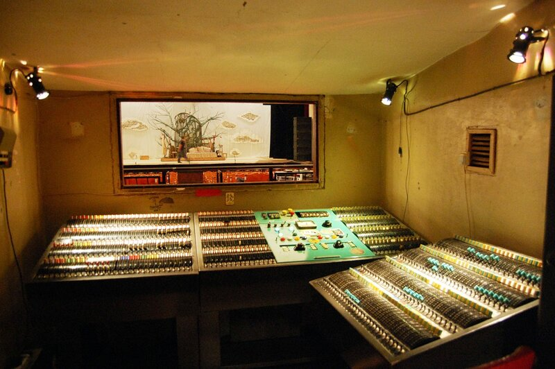
Initially, in stage lighting, a panel with a large number of manual potentiometers that controlled the lanterns was used as a control panel (console). Electricity was supplied from the "console" to the lighting sources via large power cables. Such a system was cumbersome and not the easiest to manage.
The first step in simplifying the process was connecting motors to potentiometers. In this arrangement, the engineer controls the motors and the motors the potentiometers. The bulky panel can be hidden under the stage, and a compact engine control panel can be put into the hands of the lighting technician. However, the motors have limited speed, which negatively affects the system.

Soon, dimmers appeared - devices that, on a signal from the remote control, change the voltage on the lighting fixtures, thereby adjusting the brightness. In the analog era, there was no single standard that regulated communication between remotes and dimmers. Low voltage direct current was used for control, and the most widely used analog interface was 0-10 volts.
analog interface source had a number of problems. First, the use of low voltage and one wire per channel led to induction in the circuit. Second, as the number of devices increased, the system became more difficult to maintain and troubleshoot. The use of equipment from different manufacturers required additional adapters and amplifiers to match equipment with different interfaces.
With the advent of computers, manufacturers began to add digital content to control panels.
DMX512
The transition to digital is associated with the creation of many proprietary protocols that are incompatible with each other. This state of affairs did not suit end users, since the entire set of equipment had to be from one manufacturer. In such circumstances, the need for a common standard is obvious.
The United States Institute for Theater Technology (USITT) in 1986 developed the DMX512 standard , designed to unify the communication of control panels and end devices.

DMX512 is based on the industrial EIA / TIA-485 interface, better known as RS-485. The data is sent as a differential signal, which greatly reduces the effects of line noise. The standard prescribes the use of five-core cables:
- screen;
- negative signal wire;
- positive signal wire;
- negative reserve wire;
- positive standby wire.
However, the revisions of the 1986 and 1990 standard do not specify the purpose of the spare pair, so it is acceptable to discard it and use three-wire wires, such as a microphone cable. However, phantom microphone power (+48 V) can damage DMX-compatible equipment, and DMX signals from the console can damage the microphone. Therefore, the standard prescribes the use of XLR-5 connectors.
One DMX512 line accommodates 512 channels, that is, one DMX512 wire is equivalent to 512 analog 0-10V wires.
The stage equipment is mainly multi-channel. One channel controls one equipment parameter. So, a simple RGB spotlight will be three-channel, where each channel determines the brightness of the corresponding component.
DMX512 supports daisy chain connection. So, one line can go from the control panel, which is connected to the input of the first device, and the second device is connected to the output port of the first. This method, however, has limitations. First, the total "consumption" of channels should not exceed 512 channels. Secondly, no more than 32 devices are allowed on the line. It must necessarily end with a terminator if there is no internal termination in the last device.
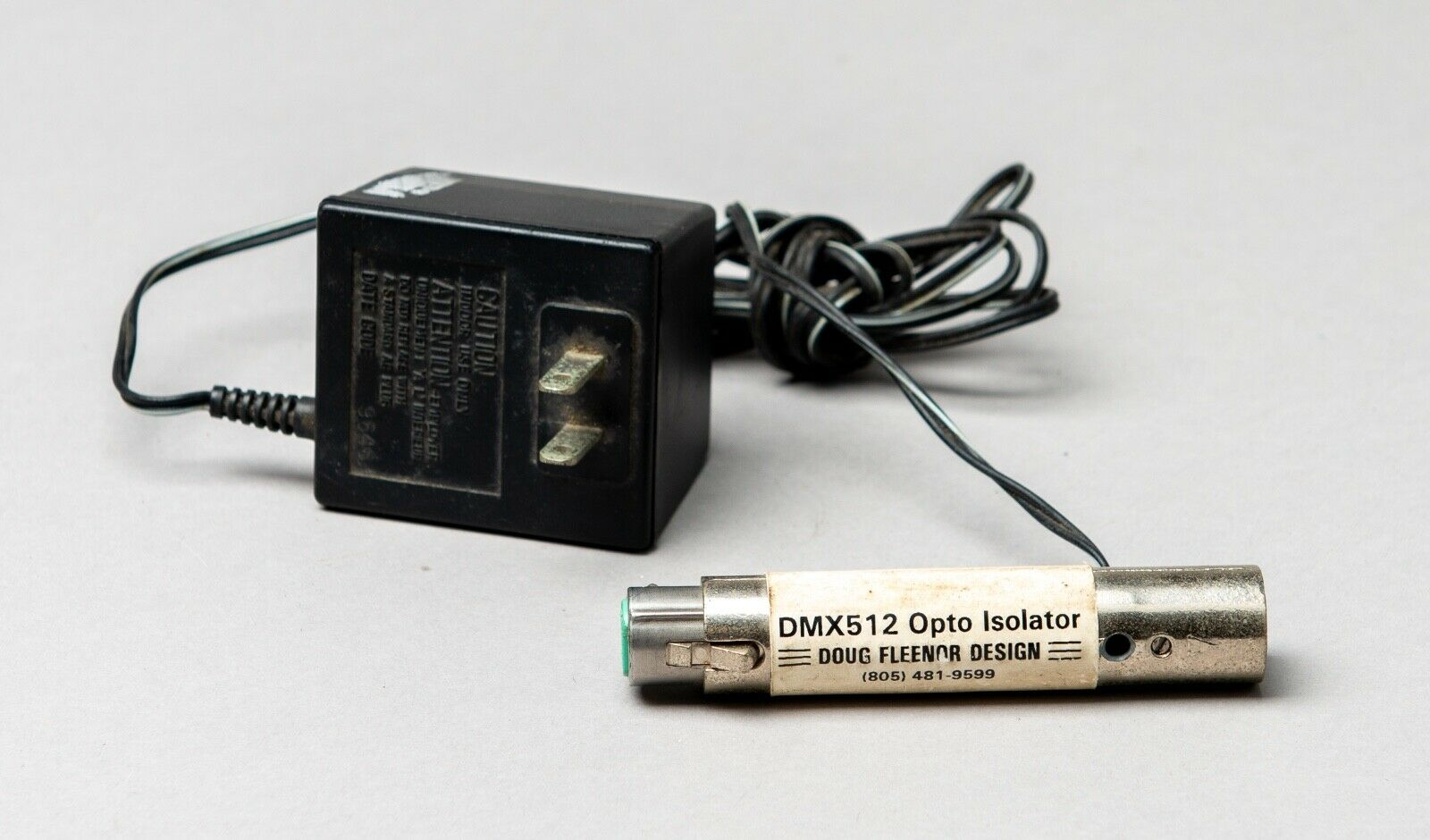
It is worth noting that DMX512 uses a low-voltage, low-power connection to control powerful devices. High voltage breakdown in the dimmer can be transmitted to the DMX line and damage the console. To prevent such situations, an optical isolator has been developed. This device converts electrical DMX signals to optical, and then immediately converts the optical signal back to electrical. Thus, the "gentle" control panel is electrically isolated from the end devices.
The console provides several DMX ports. Each DMX port, also called a DMX Universe, provides up to 512 channels. Each channel transmits exactly one byte of data, that is, a number from 0 to 255. Transmitting a DMX frame with a maximum length of 23 ms, which limits the update rate to 44 times per second.
The DMX512 standard has not changed since 1990. However, in 1998, the Entertainment Services and Technology Association (ESTA) began to revise the standard to be ANSI standards. In 2004, DMX512 was standardized as DMX512-A and then revised again in 2008. The most current version at the time of writing is "ANSI E1.11-2008, USITT DMX512-A".
With the development of technology, devices with more than 512 channels began to appear. There was a need to develop a new standard that would elegantly solve this problem.
DMX512 over Ethernet
The solution to the problem of limited DMX lines was quite simple. It is necessary to change the data transmission medium to Ethernet, which has already proven itself and is used everywhere. Thanks to this solution, it is possible to transmit multiple DMX areas in one cable. To connect devices with DMX connectors, special converters are used that extract DMX data from packets and send them to the connected devices.
There are currently two competing solutions for sending DMX512 over Ethernet:
- Art-Net;
- sACN.
Let's consider each of them.
Art-Net
Artistic License in 1998 released the first version of Art-Net, a protocol for transmitting DMX data over IP. At the heart of the protocol were broadcast messages to relieve users of network configuration. Art-Net I was designed on 10 Mbps networks, which withstood an average of 10 DMX areas, and the effective limit was 40 Mbps. However, with the widespread adoption of RGB LEDs, the number of channels grew and the broadcast message approach was placing a heavy strain on networks.
In order to somehow fix this problem, the next version was released in 2006 - Art-Net II. It was also based on broadcast messages, but the console mapped DMX areas to specific devices and went on to address distribution. At the same time, the limit for the number of DMX areas expanded to 256. In subsequent releases, the number grew to 32768.
Art-Net did not become an officially recognized standard, but is still used today. The modern version of Art-Net IV allows you to work with devices that only support the standardized sACN protocol.
ACN and sACN
The Architecture for Control Networks (ACN) and Streaming ACN (sACN) protocols are a 2006 standardized set of protocols for controlling entertainment equipment in live performance and / or at large scale.
ACN defines a modular network architecture that includes two network protocols, a Device Description Language (DDL) and profiles for interoperability (E1.17 Profiles for Interoperability). The ACN suite of protocols was originally designed to work over UDP / IP, so it will also work on IP, Ethernet and 802.11 (Wi-Fi) networks.
Modularity makes ACN easy to expand. One of the extensions, ANSI E1.31, also known as Streaming ACN (sACN), is used to send DMX data over ACN-compliant networks. Compared to Art-Net, sACN supports up to 65535 DMX areas.
Conclusion
The techniques for creating light shows have evolved significantly since their inception. In the analog era, there was no single standard, but relative interface compatibility mitigated the problem. With the transition to digital, many incompatible proprietary protocols have emerged, which have been successfully supplanted by the standardized DMX512. At the moment, there is a transition of DMX to Ethernet in the form of two competing protocols E1.31 and Art-Net. Who will be the winner - time will tell.