Introduction
Linear Feedback Shift Register (LFSR) is a shift register of bit words, in which the value of the input bit is uniquely set by some function based on the values of the remaining bits of the register before the shift. The shift register can be some kind of electrical circuit composed of discrete components: transistors, resistors, can also be integrated into a microcircuit or implemented in a program. The addition of feedback turns the shift register into a pseudo-random number generator, which is widely used in cryptography. In this article, we will analyze the principle of operation of RSLOS from hardware to its various applications.
A register, in general, is a circuit consisting of interconnected one-bit memory elements. Such circuits can write, store, read n-bit binary data. The article discusses a kind of register called shift register. Most often, the shift register is assembled on the basis of serially connected D-flip-flops, and the number of these flip-flops is equal to the number of bits n. We begin this article with the principles of the D-trigger.
D-trigger
Let's briefly touch on the very basics. Globally, electronics can be divided into two sections: analog and digital. The principal feature of the second is that the signals are set by discrete voltage levels. Moreover, there are only two discrete levels. Thus, instead of recording the voltage in volts, it is sufficient to simply name one of the two discrete levels. This is how the names "zero" and "one" appear. In fact, they define some voltage levels, which can be anything. Although, in most cases, "zero" means the level of 0 volts, and "one" the level of 5 V, 3.3 V, 1.8 V, 1.5 V, etc. Thus, the phrase "at the input zero, at the output one" means: "at the input voltage corresponding to the level of zero, at the output voltage corresponding to the level of one."
Let's move on. Now that we have a digital signal, what fun can we do with it? Apply for a D-trigger and see what happens! But first, let's give a couple of definitions.
T rigger is an electronic device capable of being in one of two stable states for a long time and alternating them under the influence of external signals.
D-flip-flop - a flip-flop that maintains the state of the input. Moreover, this state is displayed at the output
D- , . : D (), C ( , , , clk, clock) Q (). : , , . , , .
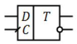
. 1 - D-
D- : C, . . . - «», «», «».
|
|
||
(D) |
(Q) |
(D) |
(Q) |
0 |
0 |
0 |
0 |
0 |
1 |
0 |
0 |
1 |
0 |
1 |
1 |
1 |
1 |
1 |
1 |
« ». , ( ) . , . , .. . , , . , .
, . D- . , . , , . D-, .
, n D-. . , , . .
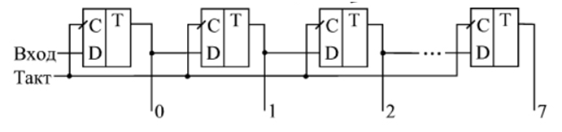
? , , , . . «» . , , . ? ( ). . . , , , . . . , , . , : .
№ |
|
0 |
1 |
2 |
3 |
0 |
1 |
0 |
0 |
0 |
0 |
1 |
0 |
1 |
0 |
0 |
0 |
2 |
0 |
0 |
1 |
0 |
0 |
3 |
0 |
0 |
0 |
1 |
0 |
4 |
0 |
0 |
0 |
0 |
1 |
5 |
0 |
0 |
0 |
0 |
0 |
- . . ? , . . , , , , . .

hi - , . .
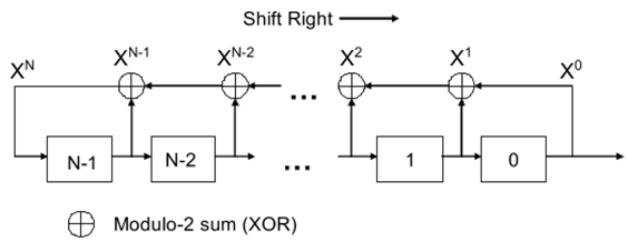
? . , , . , , 1 , . . . , .
, . ? , , . n , n . , . Xi. , . . . N, Xi+N = Xi i. 2n-1, -. , , 2n-1. .

GF(2). . t + 1, (x) p:

Y(t) t. T – n :

, , . , GF(2) - : k 2k-1. . , . , . .
n |
LFSR-2 |
LFSR-4 |
2 |
2, 1 |
|
3 |
3, 2 |
|
4 |
4, 3 |
|
5 |
5, 3 |
5, 4, 3, 2 |
6 |
6, 5 |
6, 5, 3, 2 |
7 |
7, 6 |
7, 6, 5, 4 |
8 |
|
8, 6, 5, 4 |
, , . , n= 8 :

. : . . , . , , , . . : .

. . . . 2n1 , 2n2, . ., 2n1+n2+… , n1, n2, … .
. . . — 2017. — 117 .
. . . — , 2008. — 314 .
Eastlake D., Schiller J., Crocker S. Randomness requirements for security. — 2005. — 48 .