When we met, everything turned out to be rather commonplace. The machine looked something like the picture:
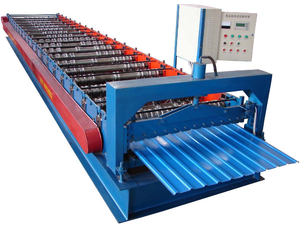
Its work is simple. There are two motors - one pulls the sheet horizontally through the shafts, which give the sheet the shape of a metal profile, and the second motor starts a press with a knife, which cuts off this sheet. Everything is controlled through the controller. A frequency drive was connected to it to control the broaching engine, a sensor for a press with a cutter and, of course, an encoder.
Part of the machine diagram:

After studying the diagram of this machine, I decided to connect to the encoder and read values from it directly. This is how it looks:
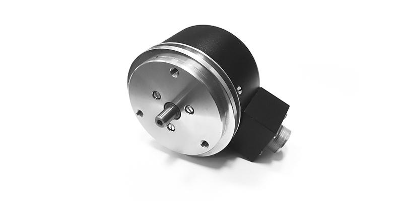
The principle of operation is simple. A disc is attached to the shaft, holes on the disc are all over the disc. On one side of the disk there is a photodetector, on the other a photosensor. When the disk is twisted, the pulses are removed from the photodetector, received due to its illumination from the diode. Depending on the model, the disk has a different number of holes, respectively, and a different number of pulses at the output of the encoder per revolution. In my case, there were 1000 of them. The signal comes out as a differential pair.
After a little thought, I threw a schematic for atmege8 and esp8266. My partner assembled it on the installation and I began to test it in real conditions, namely, I left it on the street overnight, since the machines are located in unheated rooms at the facility. The weather was also lucky. It was -35. Here is a photo of what my yard dog looks like after a night with such a temperature.

Here is a video of the tests immediately after the cold.
She handled the first request with a bang, but the subsequent requests that were supposed to display service data she displayed crookedly.
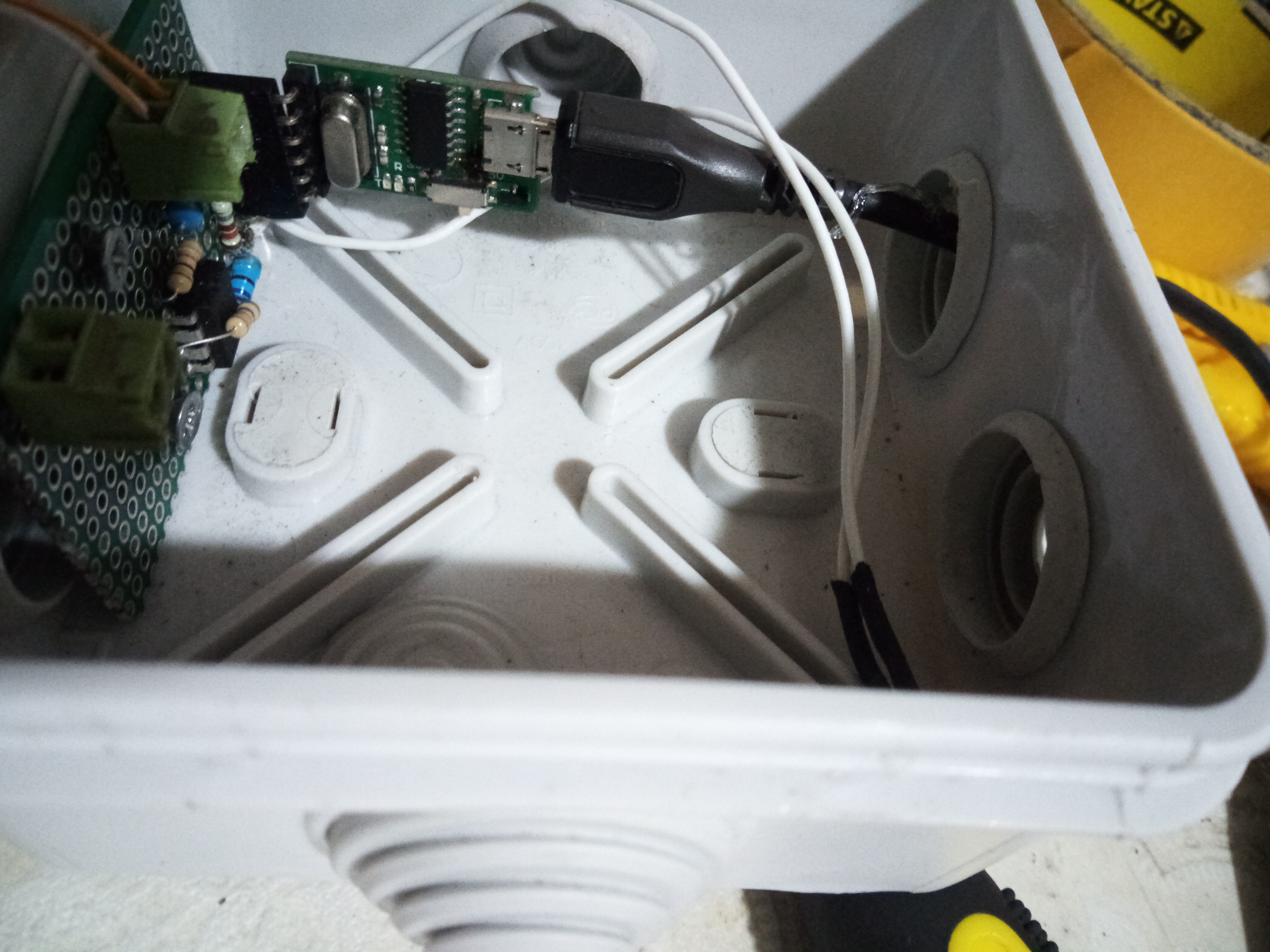
Well, I decided to redo everything for the 485 interface. Here is the final schematic of the device.

Everything is powered through a ready-made disi converter for 2576.
The output signal level of the encoder is 24 V.
Photo device. It consists of two parts
1 this is the block itself for counting pulses from the encoder and transmitting them via 485 interface

2 is a block converter from 485 to usb to max485 and ch341g

Well, and the final video from the tests: