In general, analog technology, especially at radio frequencies, is not my strong point, I am more into microcontrollers, and even made some receivers on them, for example here and here .
But sometimes you want something warm and analog.
There are several options for constructing radio receivers for medium waves. The most common ones are superheterodyne and direct gain receiver. I chose direct amplification not because it is supposedly easier to manufacture, but because a well-built receiver sounds better. The disadvantage is low selectivity. But a well-tuned direct amplification receiver has no worse selectivity, and at the same time is free of noise from the mirror channel, as well as interference whistles from frequency conversion.
So, decided, direct gain. The block diagram is as follows:

Input circuit
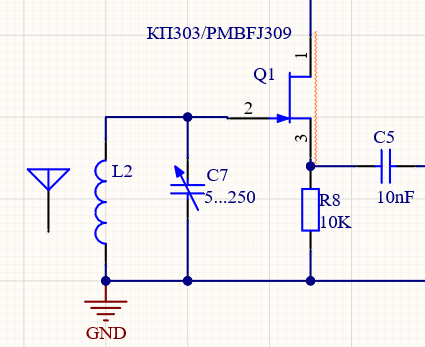
We will simplify it. If you put a UHF field-effect transistor with a high input resistance at the input, then the coupling coil will not be needed, and without it the quality factor of the input circuit will increase. KP303 is more affordable, but PMBFJ309 is much less noisy. In the input stage, this is important, I tried both, the difference is audible. The circuit diagram with the input stage will look like this:
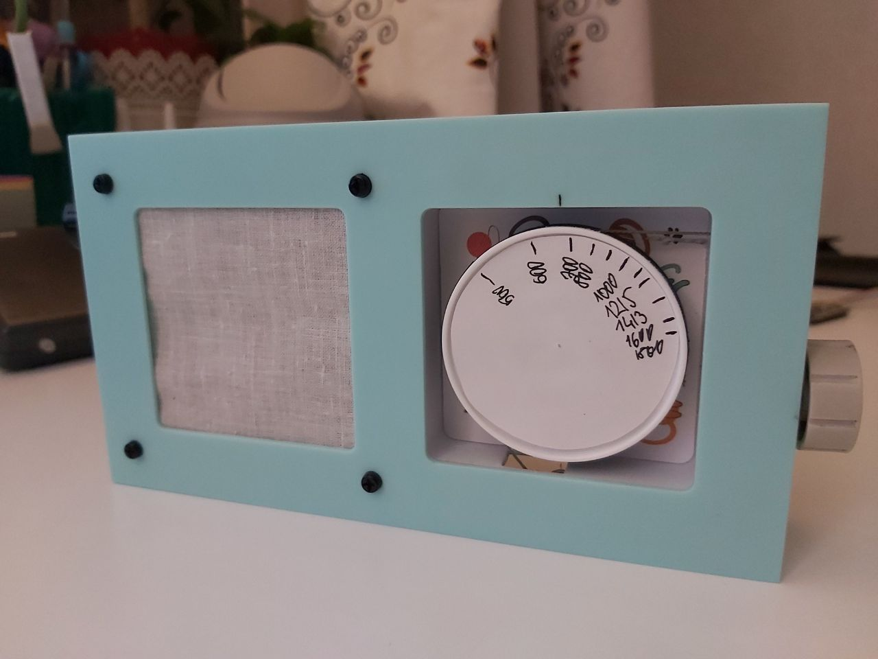
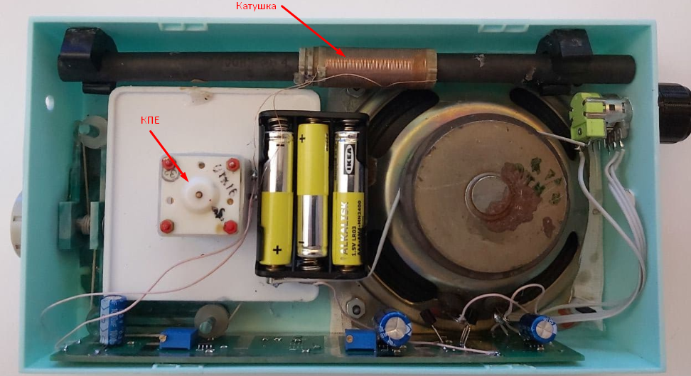
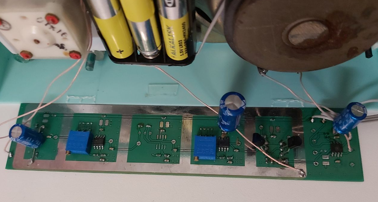
I took the coil ready from the old receiver G1ala, bought at Avito for 500 rubles. From him he took a variable capacitor, and a vernier system, which simultaneously acts as a frequency display scale. The speaker is also from there. All this was placed in the case of the watch, bought for 200 rubles at the fix price. These details made up 90% of the design, excluding the board, but let's talk about it separately, but for now, a photo of the receiver from the inside:
By the way, if you take a variable capacitor with an air dielectric, the Q-factor of the circuit, and with it the selectivity of the receiver will be much better, I checked. But this time I am limited by the size of the case, so there is a simpler KPE.
UHF
High-frequency amplifier was decided to be made on operational amplifiers. They give good amplification, and the switching circuit is simple. I took a dual AD8092 first and built 2 amplification stages on it. But firstly, it is also noisy, and secondly, when both amplifiers are in the same case, with a large overall gain, such an amplifier began to start up. As a result, it was decided to take 2 separate amplifiers, to spread them further on the board. At the same time, I picked up an op-amp from a low-noise series, specifically AD8651As a result, the UHF circuit turned out to be as follows:
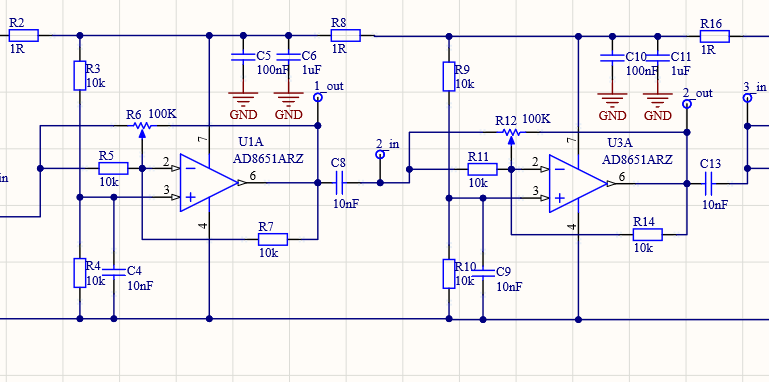
It is not difficult to guess that the power lines go from above and below :) R8C5C6 chains and similar ones in other stages are designed to separate the stages in terms of power to avoid feedback through the supply line.
The op amps are connected in a negative feedback circuit. It is set by the subscript resistors R6 and R12. They are duplicated by constant resistors R5R7 R11R14 if you suddenly want to make the gain fixed. Dividers R3 R4 R9R10 set the offset to the op amp equal to half the supply voltage. And blocking capacitors C8 C13 remove this constant component.
Such a simple amp allows you to get from "nothing" at the output of the magnetic (!) Antenna a signal with a swing of several volts, up to the supply voltage. The only thing that is needed is to adjust the gain with dividers or trimming resistors so that there is no over-amplification.
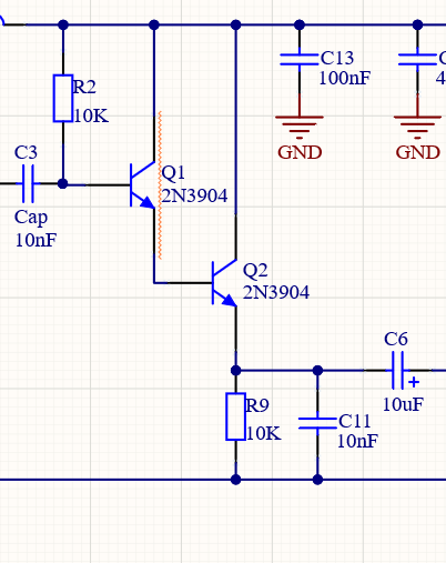
Amplitude detector.
The detector, or rather, its linearity, greatly affects the sound quality of the receiver, so I used the detector as much as 2 transistors, I don't remember from which circuit, in general, use the detector fire!
ULF
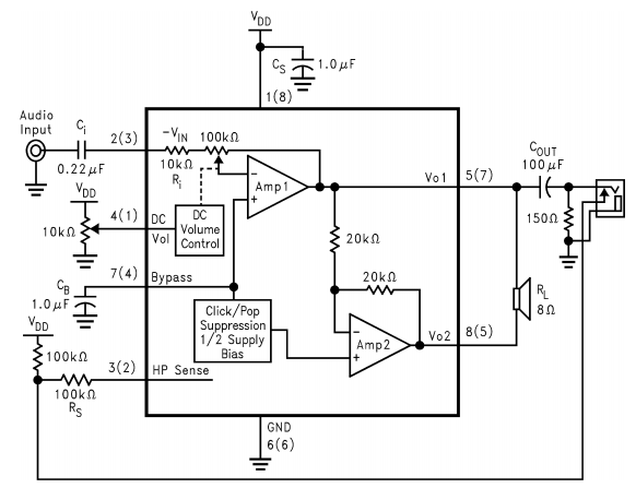
Here I went in a not quite standard amateur radio path, and did not take the first popular microcircuit like TDA2822D or lm386 that came across... More precisely, I took them, soldered them, and I heard that they were making noise like a VORTEX vacuum cleaner, even if no signal was sent to them. When receiving on a magnetic antenna, many stations can be lost in this noise. Therefore, I went to the TI website in the speaker amps section , and began to look at what they have there straight from the tin, and even to sell them in KOMPEL and CHIPDIPE. I chose the LM4865M chip . Less noisy, 5-volt power range, 750mW output, minimum strapping.
And two more interesting nuances. Its volume control is not a potentiometer at the input, but a constant voltage. That is, the potentiometer is turned on between power and ground, and the varying DC voltage at its middle pin changes the volume. This is good because there is no useful signal on the volume control resistor, as well as on the noodles of wires going to it. It does not pick up on the other circuits of the receiver, nor does it pick up any interference. The second nuance of this chip is the ability to connect headphones to its output, and a built-in circuit that detects whether headphones are connected and switches the operating mode of the amplifier.
Here is the ULF circuit (from the datasheet, I repeated it 1 in 1):
Board
Let's move on to the tastiest. Having choked with grief with self-excitation of the device, when assembling on a breadboard, I decided not to save on the PCB, and spread the cascades quite widely. I also made strips between them without a mask - in order to solder the screen if something. The screen was not needed. But the power supply capacitors had to be fully soldered, without them, the power supply of the receiver would start, be healthy. It is normal with electrolytes. The board without components looks like this:

And with the components like this:
An attentive reader may notice the third unused UHF stage on the board. When laying out, I decided to lay it down, suddenly it turns out to be not enough. But it turned out not enough, 2 stages give the necessary gain, despite the fact that they do not work for all.
And what is the result?
On NE, even in Moscow, even in an apartment, you can catch a couple of stations quite legibly. And on the street, on good days until 10. I also conducted an experiment in Voronezh, in an apartment on the 8th floor. There, it was possible to confidently receive about 20 radio stations on a magnetic antenna, albeit with an air KPI, otherwise, due to low selectivity, they merged.
How the radio works on an ordinary Moscow night in the courtyard of a residential building, watch the video:
It turned out, probably, a little out of a cannon for sparrows, but after all, it should be a hobby - a little senseless :) And also, here is the whole scheme , suddenly someone wants to repeat it.