Many have read my post " RFID Emulator ", where I talked in detail about the EM Marine device, how to wind an antenna, and how to make an RFID emulator from three parts. But, let's be honest, despite the ingenious simplicity of that device, it is difficult enough to repeat. Not everyone has an oscilloscope at home, in order to catch the resonance, and a separate programmer is required for the ATtiny85 firmware.
Therefore, I decided to make such an emulator that even a child can repeat. All components are sold in almost every village. Moreover, its functionality can even be expanded. For example, you can save several cards in it, or you can add another reader and save all cards in one device, or use it for ... So, let's go.
Hardware
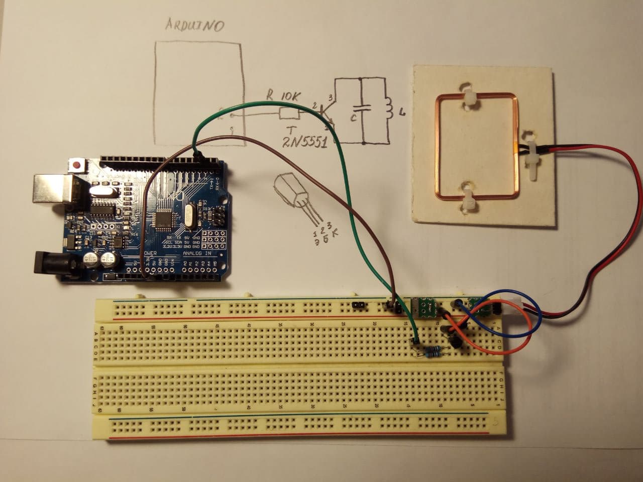
As I said, the emulator should be built using available components that can be easily obtained. First, let's look at the emulator circuit.

We have an oscillatory circuit, which we will close at a certain time with a transistor, and thus the current in the reader will change, and it will receive the transmitted data.
The most difficult thing for us in this connection is the oscillatory circuit tuned to a frequency of 125 kHz. And there is a very simple solution where you can get it from. There is a RFID tag reader for the Arduino RDM6300 on sale . The reader costs mere pennies, and it already comes with an antenna, and the resonant capacitor is already soldered on the board. Thus, in fact, we only need a reader for two parts: the coil and the resonant capacitor.

RDM6300 reader and resonant capacitor location.
I bought this reader for some penny, which is incommensurate with the labor of winding and tuning an antenna. The most difficult operation for us is to unsolder this capacitor and solder it to the circuit board. I believe that even a primary school student can cope with it.
As a result, we collect everything on a breadboard. I have two resistors in parallel only because I did not have 10 kOhm resistors at hand, but only 20 kOhm.
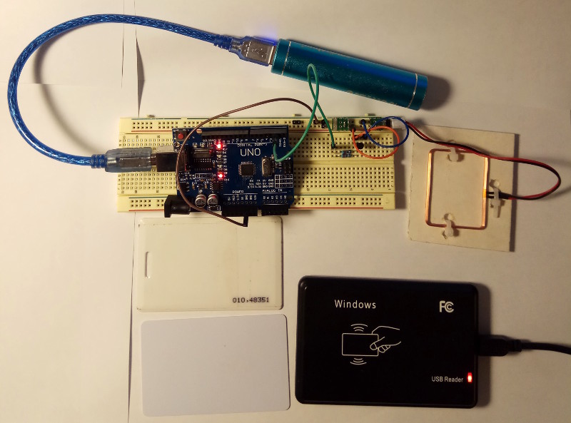
Assembled circuit.
Well, let's see in close-up how it all looks. I specially allocated a separate scarf for the capacitor, where it is soldered directly onto the mounting needles that are inserted into this mattress.

In order to check the operation of the emulator, I initially thought to use the same RDM6300 (I bought two of them). And even at first he did it, but then he decided that it was somehow not serious, one Arduina to debug the other, and went broke on a factory reader.

Factory reader.
Cocking the timer
I told most fully all the physics of the process and the principle of operation in my previous article , so I strongly recommend that you familiarize yourself with it. However, to understand what I am doing, I will refresh some points a little.
Let me remind you that the EM4102 uses the Manchester encoding scheme. When the EM4102 protocol is modulated, the transmission time of one bit can be 64, 32 or 16 periods of the carrier frequency (125 kHz).

Simply put, when transmitting one bit, we change the value of either one to zero (when transmitting zero), or from zero to one (when transmitting one). Accordingly, if we choose to transmit one bit of information 64 periods of the carrier frequency, then for the transmission of "half-bit" we will need 32 periods of the carrier frequency. Thus, each nibble should change at a rate:
f=125000/32 = 3906,25
The period of this "half-bit" will be equal to 256 ms.
Now we need to calculate the timer so that it jerks our leg with a given frequency. But I became so lazy that when I opened the datasheet and started yawning, I decided to find some ready-made solution. And it turned out that there are ready-made timer calculations, just drive in your data. Meet: timer calculator for Arduino .
We only need to set the timer frequency to 3906 Hz, and we will immediately generate a ready-to-use code. Well, isn't it a miracle!

Please note that I entered the frequency as whole, and he counted it as fractional and exactly the one that we need. I got the following timer initialization code:
void setupTimer1() {
noInterrupts();
// Clear registers
TCCR1A = 0;
TCCR1B = 0;
TCNT1 = 0;
// 3906.25 Hz (16000000/((4095+1)*1))
OCR1A = 4095;
// Prescaler 1
TCCR1B |= (1 << CS10);
// Output Compare Match A Interrupt Enable
TIMSK1 |= (1 << OCIE1A);
interrupts();
}
Brilliant, simple, concise.
The interrupt vector for output is also very simple. Let me remind you that we need to make the transition from one to zero in the case of transferring zero, and from zero to one, in the case of transferring one (see the figure for understanding). Therefore, we look at what we are passing now and where we are in the “half-bit”, gradually reading all the data from the data array.
ISR(TIMER1_COMPA_vect) {
TCNT1=0;
if (((data[byte_counter] << bit_counter)&0x80)==0x00) {
if (half==0) digitalWrite(ANTENNA, LOW);
if (half==1) digitalWrite(ANTENNA, HIGH);
}
else {
if (half==0) digitalWrite(ANTENNA, HIGH);
if (half==1) digitalWrite(ANTENNA, LOW);
}
half++;
if (half==2) {
half=0;
bit_counter++;
if (bit_counter==8) {
bit_counter=0;
byte_counter=(byte_counter+1)%8;
}
}
}
Translating data for transmission
Here, too, you should refresh the memory of the data formats stored on the card. The way they are written. Let's take a live example.
Suppose we have a card, but no reader. Number 010.48351 is written on the card .

A real card with the number 010, 48351.
How can we translate this number into the serial number that is written on the card? Simple enough. Remember the formula: we translate the two parts of the number separately:
010d = 0xA 48351d = 0xBCDF
So, we get the serial number: 0xABCDF. Let's check it, read the card with a reader (it reads in decimal format), we get a number:
0000703711
We translate it into hex-format with any calculator and get again: 0xABCDF.
It seems so far simple, wait, now you have to strain your brains. Let me remind you of the format of the data that is on the card itself.

I will put it in words:
- There are nine heading units in the beginning.
- Lowest half byte client ID.
- At the end there are parity bits.
- The second half of the byte is the client ID.
- Parity bit.
- The least significant half byte of the zero byte of the serial number.
- Parity bit
- .
- ,
- . 10 ( ).
- , .
In total, we get 64 bits of data (that's five bytes!). As a side note, my reader does not read the client ID, and I accept it as zero.
What is a parity bit? This is the number of ones in the package: if it is even, then the parity bit is zero, if not, then one. The easiest way to calculate it is just a regular XOR.
In fact, I thought for a long time how to make the conversion of the serial number into a package more elegant, so that it took up less space in the microcontroller. Therefore, I sketched out a small program that does this. The program can be viewed under the spoiler.
Test program for translating serial into data
#include <stdio.h>
#include <stdlib.h>
#include <stdint.h>
#define BYTE_TO_BINARY_PATTERN "%c%c%c%c%c%c%c%c"
#define BYTE_TO_BINARY(byte) \
(byte & 0x80 ? '1' : '0'), \
(byte & 0x40 ? '1' : '0'), \
(byte & 0x20 ? '1' : '0'), \
(byte & 0x10 ? '1' : '0'), \
(byte & 0x08 ? '1' : '0'), \
(byte & 0x04 ? '1' : '0'), \
(byte & 0x02 ? '1' : '0'), \
(byte & 0x01 ? '1' : '0')
#define NYBBLE_TO_BINARY_PATTERN "%c%c%c%c"
#define NYBBLE_TO_BINARY(byte) \
(byte & 0x08 ? '1' : '0'), \
(byte & 0x04 ? '1' : '0'), \
(byte & 0x02 ? '1' : '0'), \
(byte & 0x01 ? '1' : '0')
int main() {
//unsigned long long card_id = 0x00000ABCDF;
//uint64_t card_id = 0x00000ABCDF;
uint64_t card_id = (uint64_t)3604000;
uint64_t data_card_ul = 0x1FFF; //first 9 bit as 1
int32_t i;
uint8_t tmp_nybble;
uint8_t column_parity_bits = 0;
printf("card_id = 0x%lX\n", card_id);
for (i = 9; i >= 0; i--) { //5 bytes = 10 nybbles
tmp_nybble = (uint8_t) (0x0f & (card_id >> i*4));
data_card_ul = (data_card_ul << 4) | tmp_nybble;
printf("0x%02X", (int) tmp_nybble);
printf("\t"NYBBLE_TO_BINARY_PATTERN, NYBBLE_TO_BINARY(tmp_nybble));
printf("\t %d\n", (tmp_nybble >> 3 & 0x01) ^ (tmp_nybble >> 2 & 0x01) ^\
(tmp_nybble >> 1 & 0x01) ^ (tmp_nybble & 0x01));
data_card_ul = (data_card_ul << 1) | ((tmp_nybble >> 3 & 0x01) ^ (tmp_nybble >> 2 & 0x01) ^\
(tmp_nybble >> 1 & 0x01) ^ (tmp_nybble & 0x01));
column_parity_bits ^= tmp_nybble;
}
data_card_ul = (data_card_ul << 4) | column_parity_bits;
data_card_ul = (data_card_ul << 1); //1 stop bit = 0
printf("\t"NYBBLE_TO_BINARY_PATTERN"\n", NYBBLE_TO_BINARY(column_parity_bits));
printf("data_card_ul = 0x%lX\n", data_card_ul);
for (i = 7; i >= 0; i--) {
printf("0x%02X,", (int) (0xFF & (data_card_ul >> i * 8)));
}
printf("\n");
return 0;
}
The most important thing for us is what the parity bits will look like. For convenience, I made the output to the screen in exactly the same way as in this plate. As a result, it turned out like this.

card_id is the serial number of the card (which we talked about above).
The first column is the nibls, the second is their bit representation, the third is the parity bit. The third line from the bottom is the parity bits of all nibls. As I said, they are calculated simply by XOR.
Having tested the calculations, having checked them visually, I checked the resulting data in the program on Arduino (the last line is specially for inserting into the code). Everything worked fine. As a result of sketching this program, I got a ready-made recalculation function. Before, beat calculations were someone else's computer programs and I didn't like their monstrous implementation. Thus, the function of converting the serial number into the transmission format looks like this:
#define CARD_ID 0xABCDF
uint8_t data[8];
void data_card_ul() {
uint64_t card_id = (uint64_t)CARD_ID;
uint64_t data_card_ul = (uint64_t)0x1FFF; //first 9 bit as 1
int32_t i;
uint8_t tmp_nybble;
uint8_t column_parity_bits = 0;
for (i = 9; i >= 0; i--) { //5 bytes = 10 nybbles
tmp_nybble = (uint8_t) (0x0f & (card_id >> i*4));
data_card_ul = (data_card_ul << 4) | tmp_nybble;
data_card_ul = (data_card_ul << 1) | ((tmp_nybble >> 3 & 0x01) ^ (tmp_nybble >> 2 & 0x01) ^\
(tmp_nybble >> 1 & 0x01) ^ (tmp_nybble & 0x01));
column_parity_bits ^= tmp_nybble;
}
data_card_ul = (data_card_ul << 4) | column_parity_bits;
data_card_ul = (data_card_ul << 1); //1 stop bit = 0
for (i = 0; i < 8; i++) {
data[i] = (uint8_t)(0xFF & (data_card_ul >> (7 - i) * 8));
}
}
Everything, you can proceed to field tests. The source code of the project lives here .
Tests
As they say, it is better to see once than to read a thousand times. Especially for you, I recorded a movie about the work of this emulator. I wanted to test it on real hardware, and try to get into the office using Arduino, but with the damned pandemic, they are not allowed there. Therefore, full-scale tests will have to be looked at on the table, in laboratory conditions.
conclusions
I really hope that such articles will spur newbies to learn programming and electronics. And they will also contribute to the withdrawal from the market of this type of cards, as the most unprotected and unsafe, since now even a child can copy and emulate them.
I express my gratitude to Michal Krumnikl for his patience many, many years ago, when he explained to me on icq the operation of such an emulator, as well as help with developing the code. In a sense, these are his ideas and developments 13 years ago.
Links

