E-Book FeatherWing (hereinafter simply “FeatherWing”) is the simplest version of an e-book created within the project. From a functional point of view, this is an expansion board that docks with the Adafruit Feather M4 Express platform, which gives the device a microcontroller and a system for charging batteries. Almost all of the FeatherWing surface mount components are large enough to be soldered to the board by hand. This makes FeatherWing a great project for anyone looking to learn how to surface mount electronic components using soldering.
An e-book created by the Open Book project
This guide will show you how to build your own FeatherWing e-paper reader with a 4.2-inch e-paper screen and seven front panel buttons. The result is a device that is great for reading e-books. But the capabilities of the platform used in this project are not limited to this. In particular, the platform allows audio to be played through the headphone output. It makes it possible to work with information coming from sensors connected to STEMMA ports. And if you connect it to the Adafruit AirLift FeatherWing device, you can even connect it to the Internet wirelessly.
1. Preparation for work
You will need an E-Book FeatherWing PCB. You can order one on Tindie. You can also order PCB fabrication from a PCB manufacturer like OSH Park by sending them the files needed to make the board.
In addition, you will need to order the components to be placed on the board. Almost all of them can be found on Digi-Key; you can use the form for quick ordering of materials on Kitspace (eBook-Wing project). The display will come straight from the manufacturer - Good Display.
You will need the Arduino IDE along with the Adafruit SAM Board support package, which you need to work with the Feather M4 Express. In addition, the following Arduino libraries will be needed:
- Adafruit gfx
- Adafruit BusIO
- Adafruit MCP23008
- Adafruit EPD
- Adafruit SPIFlash
- SDFat - Adafruit Fork
- arduino-menusystem
- The open book
- Babel
Once you've got everything organized, configured software, and hardware components, you'll need to get ready to go. Namely, print out a list of components in which you can mark the ones that you have already soldered to the board. It is also helpful to have a printout of the back side of the board handy. It will come in handy if you cannot read the component specifications printed on the board itself. Keep a solder remover and flux on hand. They will be useful to you if you have to re-solder something. Even before starting work, it will be useful for you to watch my video on building FeatherWing, which can be found in the project repository .
2. Soldering passive components
If you have never soldered miniature electronic components and are not confident in your abilities, I suggest you do not worry about anything! This is much easier than it seems at first glance. Let's start with resistors and capacitors. Parts of standard size 0805 are used here. They are, of course, small, but not so small that they cannot be soldered by hand, without using special magnifying devices.
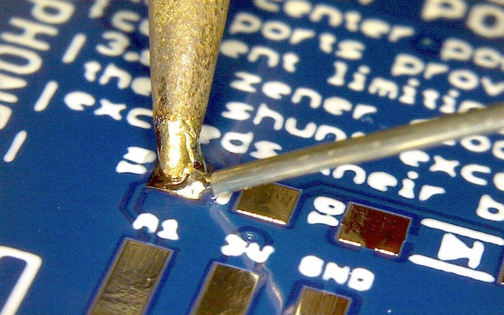
Figure A
Find the first piece you want to solder to the board. Let it be R1. First, place a drop of solder on one of the two pads (Figure A).

Figure B
Next, using tweezers, you need to place the part near the drop of solder. Now we heat the solder and move the part in the desired direction, to where the heated solder is. The part will then be locked where it should be (Figure B).

Figure C
Finally, solder the other side of the part to the other pad (Figure C).

Figure D
That's it! Detail R1 has taken its place on the board (Figure D).
Do the same for all resistors and capacitors from the parts list. Solder coil L1 in the same way.

Figure E
A very similar strategy can be used with diodes D1-D5. Just keep in mind that the diodes need to be mounted, taking into account the direction of their location on the board. There is a small gray line on the plastic case of the diode. The diode must be positioned so that this line is on the same side as the diode symbol line drawn on the board (Figure E).
Here, in addition, two types of diodes are used. Two Zener diodes should be placed in the Extra Ports block and three Schottky diodes in the E-Paper Display block.

Figure F
Now that we are working on the passive components, we can also solder the buttons to the board. They are soldered in the same way as resistors and capacitors: a drop of solder is placed on one contact pad, one of the button contacts is soldered to this pad, and then the second contact is soldered to the second pad (Figure F).
The same approach can be used when mounting MOSFET Q1. This part, however, has three contacts, so be careful and make sure that they are all securely fastened to the contact pads on the board.
3. Soldering integrated circuits

Figure G
The project uses three integrated circuits: a flash memory chip, an SRAM chip, and a GPIO port expander. When soldering them to the board, you need to pay attention to their orientation, as is the case with diodes. There is a small dot on the plastic case of each microcircuit. Its location should correspond to the point drawn on the board (Figure G).
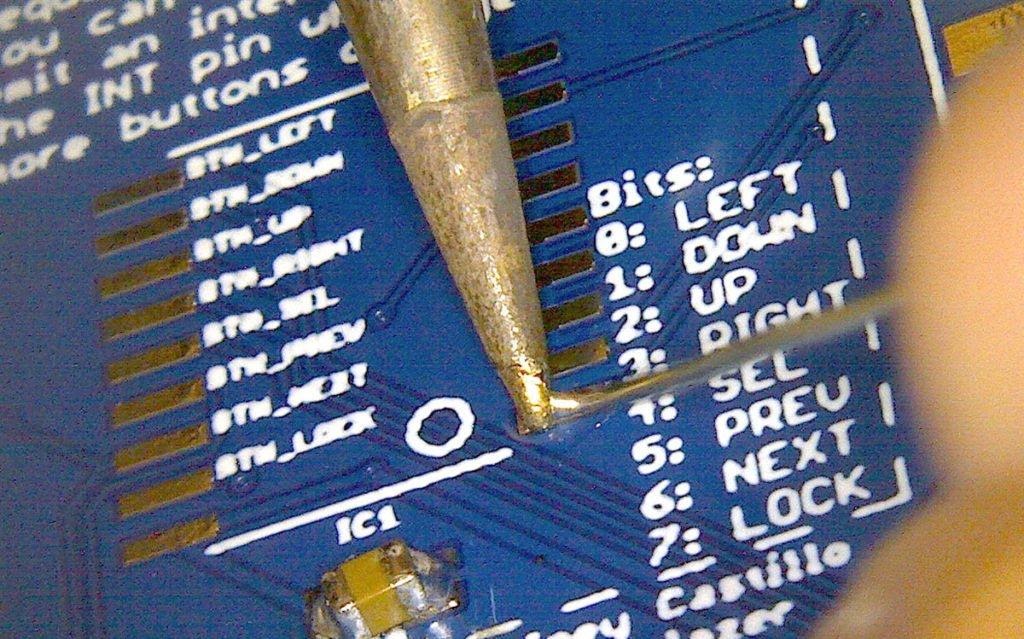
Figure H
The soldering strategy is the same here as for diodes. Namely, first place a drop of solder on one of the corner pads (Figure H).

Figure I
Then, having melted this solder, you need to place the microcircuit in the place intended for it (Figure I).
Before soldering the rest of the pins to the board, it's worth checking the chip alignment. Namely, all its outputs must be located exactly on the contact pads. If this is not the case, you need to re-melt the solder on the already soldered contact and move the chip until it is correctly aligned. Then you need to solder the output of the chip, located in its opposite corner, to the board. This will fix the chip in the correct position.
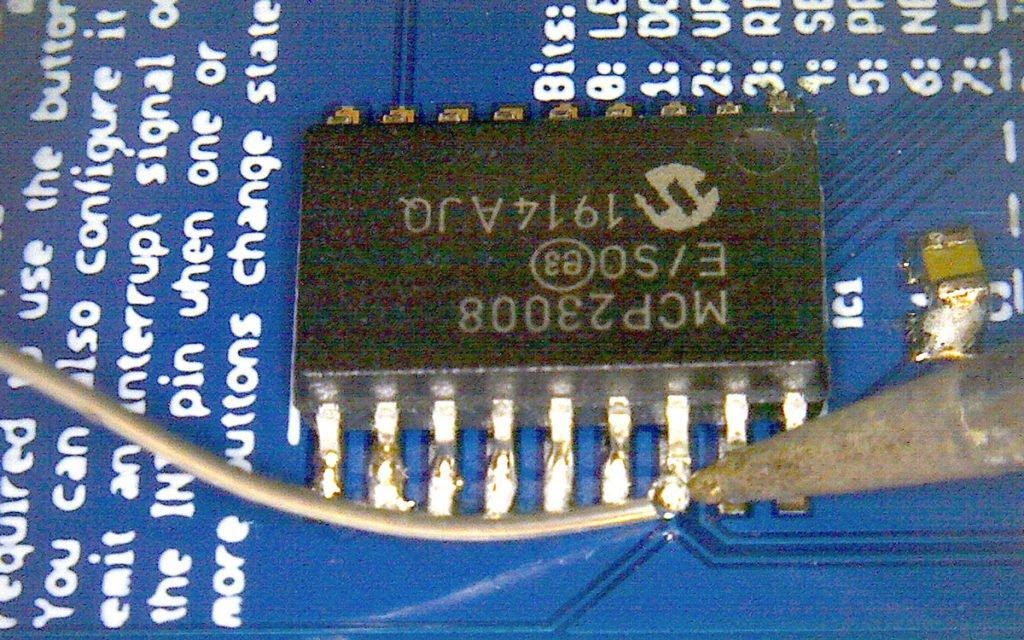
Figure J
If at this stage of work it is clear that the chip is placed correctly, you can solder the rest of its outputs to the contact pads (Figure J).

Figure K

Figure L

Figure M

Figure N
If it turns out that the solder has connected two adjacent pins - do not panic! This is called bridging. This defect is easy to fix. If the jumper is formed from a small amount of solder, you can try to fix it by using a flux and heating the leads (Figures K, L, M, N). The flux helps the solder adhere to the metal leads.

Figure O

Figure P
If you cannot get rid of the jumper using simple methods, you can resort to a solder remover. The solder must be heated and collected with this medium (Figures O and P).
4. Soldering the microSD card slot

Drawing Q
Soldering this part may seem like a daunting task, but it really isn't that bad. To begin with, just as we did last time, place a drop of solder on one of the mounting pads and, keeping the solder melted, place the microSD card slot on the board correctly (Figure Q).

Figure R
This slot has large, convenient openings at the top. They can be used to check the correct alignment of the contacts (Figure R). If they are not aligned correctly, you need to warm up the solder on the pad used to fix the slot and move the part until the contacts match the pads. Then you need to solder everything that is not yet soldered.

Figure S The
main trick here is the following: a thin solder wire is pressed against the contact, passing it through the hole in the upper part of the slot, and the soldering iron tip is brought in from the side. This is where the PCB holder comes in handy. The board can be simply placed on the edge of the table, making it convenient to work with a soldering iron.

Figure T The
correct soldering of the contacts can be checked with a magnifying glass (Figure T).
5. Soldering connectors using surface mount technology components
We need to solder seven connectors to our board. This is a headphone jack, three STEMMA ports, two Feather ports and a 24-pin display connector.
The easiest way is to solder the headphone jack. It has two plastic guides, for which there are a couple of holes on the board. The connector must be installed where it should be. After that, you just need to solder its four pins to the board.
Soldering STEMMA ports is similar to soldering ICs. Namely, you can place some solder at the pivot point, align the port with the lines drawn on the board, and then solder the rest of the pins. Note that the 4-pin port should be in the middle and the 3-pin ports should be on both sides of the board.
The same goes for Feather ports. First, one of the corners of the port is fixed, then the other, then the correct position of the part is checked, and only after that the remaining contacts are soldered. It is useful to slightly press down the port from above so that in the end it would be securely fixed to the board.

Figure U
Finally, we start soldering the 24-pin connector. This is perhaps the most difficult thing in all of our work. But, if you have a solder remover and flux at hand, you can easily cope with soldering this connector. First, as usual, place a drop of solder on one of the two large mounting pads, no matter which one. Then heat up the solder and align the connector (Figure U).

Figure V
Next, using a magnifying glass, you need to check the correct alignment of all 24 pins. Knowing if they are aligned correctly is quite simple. If the blue surface of the board is visible between all the contacts, then everything is done as it should. Then you need to stretch the soldering iron and solder along these pins and solder them! It doesn't hurt to use some flux to get the solder to stick where it should stick (Figure V).

Figure W

Figure X
Some of the pins will almost inevitably end up being connected by solder straps. But this is perfectly normal. In order to get rid of them, you need to clean the soldering iron tip, place a little flux in the problem area (Figure W) and remove the jumper from the contacts (Figure X). If the jumper is large enough, a solder remover will help remove it.
Perhaps, on the first try, you will not solder this connector, but when after a while it turns out that there are no jumpers between the contacts, and that they are all securely soldered to the board, this will mean that our business is close to completion.
6. Testing the board
In order to protect ourselves, we will use multimeters to check the 3V and GND lines for a short circuit. Switch the multimeter to Continuity mode and touch the 3V and GND pins on the Feather port with the probes. If you hear a beep, check the board for the presence of solder jumpers on it, which can connect the 3V and GND lines. If there is no sound, it means that we are ready to connect to the Feather M4 board!

Figure Y
Carefully remove the fragile e-paper display from the protective packaging. Connect the display flex cable by passing it through the hole in the board to the appropriate connector (Figure Y).
Turn the board over, taking care not to damage the display. So you can see it when working with the device. Power up Feather.
Download the sketch
Open_Book_Screen_Test
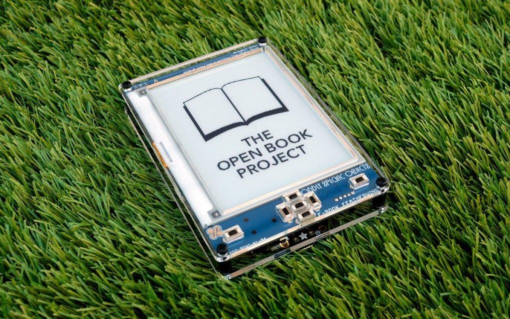
from the Open Book examples. Make sure the Feather M4 board is selected, and then run the sketch! You should see the display turn on and display the Open Book project logo on it.
7. Soldering the remaining parts
Disconnect power from the board, disconnect the display cable from the 24-pin connector and move the display somewhere.
There is one jumper that must be closed with solder. This enables the Flash chip. Find the BCS jumper that is near the top of the long Feather port and short it with a drop of solder.
Now let's get to the buttons! Insert them into the corresponding through-holes of the board, placing them on the front of the board, and then solder their pins on the back of the board.
Now place the switch on the back of the board by inserting it into the corresponding hole and then solder it to the front of the board.

Figure Z
Now, for the last time, thread the display ribbon cable through the hole in the board and connect it to the 24-pin connector. Secure the display to the front of the board using double-sided tape. Congratulations: assembly is complete (Figure Z)!
8. Writing Babel Image to Flash Chip
One of the flash chips E-Book FeatherWing is designed to store language and font information. It is now empty. When you downloaded Babel, you also downloaded a 2MB BLOB file that contains information on how to display text in all existing languages. We're going to copy this file to the microSD card and then run a sketch that will write the image to the Flash chip.

Figure Aa
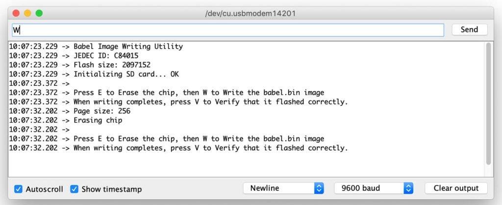
Figure Bb
Find the file
babel.bin
. It is located in the folder
babelconvert
that is included in the Babel library you downloaded (Figure Aa). Copy this file to the microSD card, and then remove it from the card reader. Now connect the card to FeatherWing. Run the
BurnBabelBurn
Babel examplessketch , open Serial Monitor and follow the instructions to write data to the chip (Figure Bb).
If the system has confirmed the correctness of the data recording, then everything is ready! Now you can delete the file
babel.bin
from the microSD card. The data is now permanently stored in the corresponding chip.
9. Reading books
Finally we got to this point! A very simple e-book reader is used here. This is an MVBook used to read text files converted to MVBook format (hopefully the device will support simple .txt files in the future).
There is a file
books.zip
in the MVBook folder that contains a small set of publicly available books. Copy the contents of this file to a microSD card and connect the card to FeatherWing.

Figure Cc
Follow the path
File > Examples > Open Book
and run the sketch
Open_Book_MVBook
. A list of book titles and authors should appear on the screen. A book selection indicator should be visible on the left (Figure Cc). Use the up and down arrow buttons to select a book, confirm your selection with the center button. In read mode (Figure Dd below), use the buttons located in the lower left and right corners of the board to turn pages. Use the center button to return to the main menu.
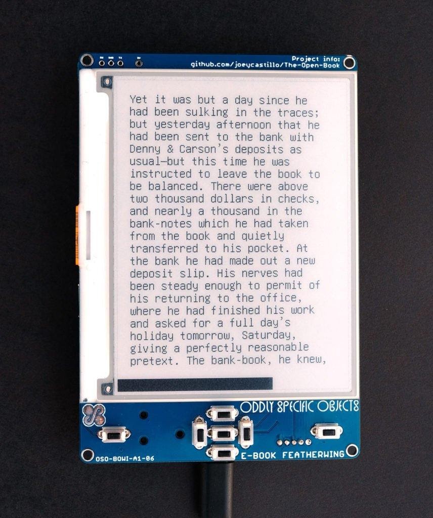
Figure Dd
E-Book FeatherWing Expansion
The E-Book FeatherWing system allows you to read e-books, but its capabilities are not limited to this.
- , . SAMD51, Feather M4, JPEG-.
- E-Book FeatherWing FeatherWing. , Wi-Fi- (AirLift), (DS3231), GPS (Adafruit Ultimate GPS).
- STEMMA, , E-Book FeatherWing — , NeoPixel.
- , Adafruit #3898 400 .
?
The Open Book project has created two devices. We just talked about assembling one of them, which is simpler. If you think you need something more, then maybe you should take a look at a more sophisticated device - Open Book Feather. Among its features are the placement of the SAMD51 microcontroller on the main board, the presence of a stereo audio output and a microphone input, a larger number of contacts for connecting additional compatible boards.
Both boards support CircuitPython, a wonderful offshoot of MicroPython by Adafruit that is great for learning and experimenting.
Additional details about the project, including information on how to make a corpus for an e-book, you can find in thisrepositories.
Planning to put together an E-Book FeatherWing?

