
We will scoff at the GD32VF103CBT6 microcircuit, which is an analogue of the well-known STM32F103, with a small but important difference: instead of the ARM core, it uses the RISC-V core. How it threatens us, as programmers, let's try to figure it out.
I will briefly list the characteristics of the controller:
• Supply voltage: 2.6 - 3.6 V
• Maximum clock frequency: 108 MHz
• ROM size (flash): 128 kB
• RAM size (ram): 32 kB
• Backup registers size (saved after reset): 42 x 16 bits = 84 bytes.
• ADC + DAC: 2 pieces of ADC with 10 channels and 12 bits each plus 2 DACs of 12 bits.
• Of course, a bunch of other peripherals like timers, SPI, I2C, UART, etc.
So, I propose to deal with the controller from scratch - the development of the board and the programming of memory cells with an electrified needle ... But no, that's too much, we'll get by with an assembler.
All sources, including the debug board diagram and code examples, can be found here: https://github.com/COKPOWEHEU/GD32VF103_tutor
-one. Printed circuit board
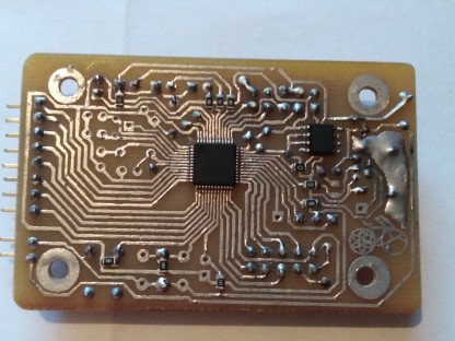
The first step is why a homemade board. Firstly, out of sports interest: if you order development, assembly and everything else in China, then where is your own contribution? And nobody canceled the pleasure of handmade work. Secondly, on a homemade board, you can bring out all the necessary connectors and controls. For example, it is very convenient when there is always at least a pair of buttons and a pair of LEDs, plus a debug UART connector. But complex peripherals like encoders, sensors or displays on such a board are not needed; it is better to connect them to the connectors.
In general, my board does not represent anything particularly new - quartz crystals, buttons, LEDs, connectors are divorced (PA0 - PA7 plus five-volt power supply and ground on the angular one, and three-volt power and ground on the two-row PB8 - PB15). The presence of a five-volt power supply on the connector allows both powering the board from an external source bypassing usb (for example, from a usb-uart adapter), and vice versa, powering external circuits from the board itself, which 3.3 V is not enough. I will
focus some attention on the UART connector, more precisely on its pinout. Unlike most "branded" boards, I have a symmetrical one, that is, there is a ground in the middle, and Rx and Tx along the edges. Thus, you can not remember the "only correct" pinout, and connect any pair of devices with a simple loop without the need to cross the wires in it.
Naturally, the Boot0 and Boot1 legs are brought out to jumpers.
There is nothing more interesting on the board.
0. Setting up the software environment
The developers of this controller offer to download an IDE from their website. But we are not going to do that: just the console, text editor and hardcore.
Here is a short list of the software used. What is nice, all the software is present in the repository, I didn't have to download anything from the GigaDevice website.
| software | description |
|---|---|
| gcc-riscv64-unknown-elf | compiler |
| stm32flash, dfu-util | Flashers via bootloader |
| kicad | Board tracing |
| screen | UART debugging |
I will dwell separately on the controller firmware. There are three main ways:
(1). JTAG — , .
(2). Bootloader.UART — Boot0 , ( , ), stm32flash (, , !)
$ stm32flash /dev/ttyUSB0 -w firmware.bin
Boot0 , ( )
(3). Bootloader.USB — , stm32flash dfu-util:
$ dfu-util -a 0 -d 28e9:0189 -s 0x08000000 -D firmware.bin
, USB , RC-, USB .
, dfu-util . - . , . Boot0 , Bootloader, Boot1. , .
0,5. ?
stm32f103 . , SPI DMA ( !) .
, GigaDevice , STMicroelectronics, . . :
| GD32VF103 | STM32F103 |
|---|---|
| RCU_APB2EN |= RCU_APB2EN_SPI0EN; | RCC->APB2ENR |= RCC_APB2ENR_SPI1EN; |
| SPI_DATA(SPI_NAME) = data; | SPI1->DR = data; |
| DMA_CHCNT(LCD_DMA, LCD_DMA_CHAN) = size; | DMA1_Channel3->CNDTR = size; |
RISCV SPI_DATA , SPI. ! - SPI0, DMA0 2 .
(https://habr.com/ru/post/496046/ : https://github.com/COKPOWEHEU/stm32f103_ili9341_models3D) :
: https://github.com/COKPOWEHEU/RISCV-ili9341-3D
1.
, -, — , — . ( , !).
. , -, . RCU_APB2EN ( 0x40021018) RCU_APB2EN_PxEN, x — . , PB5 — PB7 RCU_APB2EN_PBEN (3- , 0x8). .
la a5, 0x40021018 lw a4, 0(a5) ori a4, a4, 8 sw a4, 0(a5)
a4, a5 , . .
, . , :
.equ RCU_APB2EN, 0x40021018 .equ RCU_APB2EN_PBEN, (1<<3) //RCU_APB2EN |= RCU_APB2EN_PBEN la a5, RCU_APB2EN lw a4, 0(a5) ori a4, a4, RCU_APB2EN_PBEN sw a4, 0(a5)
. - , - , . , GPIO_CTL. - 16, 64 , 32-. STmicroelectronics . B GPIOB_CTL0 GPIOB_CTL1: PB0 — PB7, PB8 — PB15. 16 , ( ). , 5 — 7 , 0 1:
.equ GPIOB_CTL0, 0x40010C00 .equ GPIO_MASK, 0b1111 .equ GPIO_PP_50MHz, 0b0011 .equ RLED, 5 .equ YLED, 6 .equ GLED, 7 .equ SBTN, 0 .equ RBTN, 1
, 4 GPIOB_CTL0: [0, 1, 2, 3], [4, 5, 6, 7]. , 5- , , [20, 21, 22, 23]. , . , :
GPIOB_CTL0 = (GPIOB_CTL0 &~(0b1111<<(RLED*4))) | 0b0011 << (RLED*4);
4 , . , , :
la a5, GPIOB_CTL0 lw a4, 0(a5) la a6, ~(GPIO_MASK << (RLED*4)) and a3, a4, a6 la a4, (GPIO_PP_50MHz << (RLED*4)) or a4, a4, a3 sw a4, 0(a5)
. , . 0 1, - . GPIOB_OCTL, , XOR` 5- . .
.equ RCU_APB2EN, 0x40021018 .equ RCU_APB2EN_PBEN, (1<<3) .equ GPIOB_CTL0, 0x40010C00 .equ GPIO_MASK, 0b1111 .equ GPIO_PP_50MHz, 0b0011 .equ GPIOB_OCTL, 0x40010C0C .equ RLED, 5 .equ YLED, 6 .equ GLED, 7 .equ SBTN, 0 .equ RBTN, 1 .text .global _start _start: //RCU_APB2EN |= RCU_APB2EN_PBEN la a5, RCU_APB2EN lw a4, 0(a5) ori a4, a4, RCU_APB2EN_PBEN sw a4, 0(a5) //GPIOB_CTL0 = (GPIOB_CTL0 & (0b1111<<RLED*4)) | 0b0011 << (RLED*4) la a5, GPIOB_CTL0 lw a4, 0(a5) la a6, ~(GPIO_MASK << (RLED*4)) and a3, a4, a6 la a4, (GPIO_PP_50MHz << (RLED*4)) or a4, a4, a3 sw a4, 0(a5) MAIN_LOOP: //GPIO_OCTL(GPIOB) ^= (1<<RLED) la a5, GPIOB_OCTL lw a4, 0(a5) xori a4, a4, (1<<RLED) sw a4, 0(a5) //sleep la a5, 200000 sleep: addi a5, a5, -1 bnez a5, sleep j MAIN_LOOP
200000 . .
, OCTL , --. ( ), . GPIOx_BOP: 16 OCTL 0, — 1. GPIOx_BC, BOP, . . , . .
.equ GPIOB_BOP, 0x40010C10 … la a5, GPIOB_BOP la a4, (1<<YLED) | (1<<RLED*16) sw a4, 0(a5)
, .
, , OCTL`.
gcc:
$ riscv64-unknown-elf-gcc -march=rv32imac -mabi=ilp32 -mcmodel=medany -nostdlib main.S -o main.elf
, -nostdlib ( ) ` . . , , ( , ), :
$ riscv64-unknown-elf-objcopy -O binary main.elf main.bin $ riscv64-unknown-elf-objdump -D -S main.elf > main.lss $ stm32flash /dev/ttyUSB0 -w main.bin
makefile.
, COM USB . , , dialout. USB dfu-utils, udev 28e9:0189.
2.
- , GPIOB_ISTAT, , . . , :
.equ GPIO_MASK, 0b1111 # #input .equ GPIO_ANALOG, 0b0000 # .equ GPIO_HIZ, 0b0100 # .equ GPIO_PULL, 0b1000 # .equ GPIO_RESERVED, 0b1100 # , #output, GPIO, .equ GPIO_PP10, 0b0001 # push-pull , 10 .equ GPIO_PP2, 0b0010 # -//- 2 .equ GPIO_PP50, 0b0011 # -//- 50 .equ GPIO_OD10, 0b0101 # open-drain , 10 .equ GPIO_OD2, 0b0110 # -//- 2 .equ GPIO_OD50, 0b0111 # -//- 50 #output, AFIO — , .equ GPIO_APP10, 0b1001 # push-pull , 10 .equ GPIO_APP2, 0b1010 # -//- 2 .equ GPIO_APP50, 0b1011 # -//- 50 .equ GPIO_AOD10, 0b1101 # open-drain , 10 .equ GPIO_AOD2, 0b1110 # -//- 2 .equ GPIO_AOD50, 0b1111 # -//- 50
push-pull , , . 0, 1 GPIOx_OCTL. open-drain , , . 0, . « » , , I2C . OCTL. pull-up, pull-down , (pull-up), (pull-down). GPIOx_OCTL. . , . , . .
3.
. . , . , . :
| zero | x0 | n/a | |
| ra | x1 | ||
| sp | x2 | Stack pointer, | |
| gp, tp | x3, x4 | . | n/a |
| t0-t6 | x5-x7, x28-x31 | ||
| s0-s11 | x8, x9, x18-x27 | ||
| a0-a7 | x10-x17 | ||
| a0, a1 | x10, x11 |
zero , , . /dev/zero /dev/null
ra sp - .
gp tp . , . , .
t0 — t6 . , .
s0 — s11 . — - .
a0 — a7 . , , . , a0 a1, .
, , . 200`000 , . . ( ) . , a0. a1 — a7 t0 — t6, . , .
, , . ? ra, (jal, jalr call, ) , . , , , ra jr ra ret. , a5 a0:
... la a0, 200000 call sleep ... sleep: addi a0, a0, -1 bnez a0, sleep ret
4.
, ? , . , ?
, , , . , , - . : , , , , — , . . , , .
, .
: , . sp. GD32VF103 0x2000'0000 32 , 0x2000'8000, .
, 0x12, 0x34 0x56, . :
| 0 | 1 | 2 | 3 | 4 | |
|---|---|---|---|---|---|
| 0x2000`8000 | ← sp | ||||
| 0x2000`7FFF | 0x12 ← sp | 0x12 | 0x12 | 0x12 | |
| 0x2000`7FFE | 0x34 ← sp | 0x34 | 0x34 ← sp | ||
| 0x2000`7FFD | 0x56 ← sp |
, 4 0x56 , «» .
, . , RISC-V , . , , 4- 0x2000'0002 — 0x2000'0000 0x2000'0004. , — , 4-, 4- .
— . , . , , , . , sp. , ( ) . , , , , . : ( sp) . : — sp.
, :
.macro push val addi sp, sp, -4 sw \val, 0(sp) .endm .macro pop val lw \val, 0(sp) addi sp, sp, 4 .endm
, sp :
la sp, 0x20008000
, sleep -, :
sleep: push ra push s0 mv s0, a0 sleep_loop: addi s0, s0, -1 bnez s0, sleep_loop pop s0 pop ra ret
, sleep : a0. … , ! - . , , . , .
push pop, , sp 4 . ! - . , , , , sp. , :
func: addi sp, sp, -16 sw ra, 12(sp) sw s0, 8(sp) sw s1, 4(sp) sw s2, 0(sp) … lw s2, 0(sp) lw s1, 4(sp) lw s0, 8(sp) lw ra, 12(sp) addi sp, sp, 16 ret
, «» , , , , , . — sp , sp . , fp — frame pointer ( s0, ). sp, . sp, , , fp , .
, 5 ra, fp , , s1, s2 s3. :
func: addi sp, sp, -10*4 sw fp, 0(sp) addi fp, sp, 10*4 sw ra, -9*4(fp) sw s1, -8*4(fp) sw s2, -7*4(fp) sw s3, -6*4(fp) sw zero, -5*4(fp) # — data[0] sw zero, -4*4(fp) # — data[1] sw zero, -3*4(fp) # — data[2] sw zero, -2*4(fp) # — data[3] sw zero, -1*4(fp) # — data[4] … lw s3, -6*4(fp) lw s2, -7*4(fp) lw s1, -8*4(fp) lw ra, -9*4(fp) addi sp, fp, -10*4 lw fp, 0(sp) addi sp, sp, 10*4 ret
- ( ), . sp fp, . , push' pop' , , .
, fp . sp, fp s0.
5.
, . , .
— . -, . .rodata, . 4 :
.text led_arr: .short (0<<GLED | 0<<YLED | 1<<RLED) .short (0<<GLED | 1<<YLED | 0<<RLED) .short (1<<GLED | 0<<YLED | 0<<RLED) .short (0<<GLED | 1<<YLED | 0<<RLED) led_arr_end:
.short , — 2 . .
:
MAIN_LOOP: la s0, GPIOB_OCTL lh s1, 0(s0) la s2, ~(1<<GLED | 1<<YLED | 1<<RLED) la s3, led_arr la s4, led_arr_end led_loop: lh t0, 0(s3) and s1, s1, s2 or s1, s1, t0 sh s1, 0(s0) la a0, 300000 call sleep addi s3, s3, 2 bltu s3, s4, led_loop j MAIN_LOOP
. -, lw lh GPIOB_OCTL. 2-, GPIOB_OCTL, , . -, 1, . 32- , 4 , — 1.
6.
.rodata, .text. : .data .bss. , , — . .bss : , — , . , .
, .text .data, . res/firmware.lss , 0x2000'0000:
000110ea <__DATA_BEGIN__>: 110ea: 0020
, - . , . , lib/gd32vf103cbt6.ld, :
MEMORY{ flash (rxai!w) : ORIGIN = 0x00000000, LENGTH = 128K ram (wxa!ri) : ORIGIN = 0x20000000, LENGTH = 32K } SECTIONS{ .text : { } > flash .data : { } > ram .bss : { } > ram }
, . (, ) -T:
riscv64-unknown-elf-gcc -march=rv32imac -mabi=ilp32 -mcmodel=medany -nostdlib -T lib/gd32vf103cbt6.ld src/main.S -o res/main.elf
, :
20000000 <led_arr>: 20000000: 0020
, , , . , . .text, res/firmware.hex .
:08 0000 00 2000 4000 8000 4000 D8
.ld-
MEMORY{ flash (rxai!w) : ORIGIN = 0x00000000, LENGTH = 128K ram (wxa!ri) : ORIGIN = 0x20000000, LENGTH = 32K } SECTIONS{ .text : { *(.text*) *(.rodata*) . = ALIGN(4); } > flash .data : AT(ADDR(.text) + SIZEOF(.text)){ _data_start = .; *(.data*) . = ALIGN(4); _data_end = .; } > ram .bss : { _bss_start = .; *(.bss*) . = ALIGN(4); _bss_end = .; } > ram } PROVIDE(_stack_end = ORIGIN(ram) + LENGTH(ram)); PROVIDE(_data_load = LOADADDR(.data));
- _data_load . , , :
_start: la sp, _stack_end #copy data section la a0, _data_load la a1, _data_start la a2, _data_end bgeu a1, a2, copy_data_end copy_data_loop: lw t0, (a0) sw t0, (a1) addi a0, a0, 4 addi a1, a1, 4 bltu a1, a2, copy_data_loop copy_data_end: # Clear [bss] section la a0, _bss_start la a1, _bss_end bgeu a0, a1, clear_bss_end clear_bss_loop: sw zero, (a0) addi a0, a0, 4 bltu a0, a1, clear_bss_loop clear_bss_end:
Now, finally, our array will be correctly read from RAM.
When creating variables in the .bss section, it would be strange to assign them any values (although no one forbids them, they simply will not be used). You can use the .comm arr, 10 placeholder directive (for a 10 byte arr variable) instead. It should be noted that it can be used in any section, and it will only back up data in .bss. Below are some more examples of declaring variables of different sizes:
.byte 1, 2, 3 # 0x01, 0x02 0x03 .short 4, 5 # 0x0004 0x0005 .word 6, 7 # 0x0000'0006 0x0000'0007 .quad 100500 # 0x0000'0000'0001'8894 .ascii "abcd", "efgh" # 4 ( ! ) .asciz "1234" # "1234\0" - . 'i' .space 10, 20 # 10 , 20. ,
Sudden end
I didn't want to split the article into two, but what to do. In the next part, we will look at how to work with the UART debug port, with interrupts, and how to combine assembly language and C code.