I suggest that you familiarize yourself with the previously posted materials on the Starlink (SL)
project : Part 1. The birth of the project ‣ Part 2. SL network ‣ Part 3. Ground complex ‣ Part 4. Subscriber terminal ‣ Part 5. State of the SL grouping and closed beta testing ‣ Part 6. Beta-testing and service for customers ‣ Part 7. Bandwidth SL and RDOF program network ‣ Part 8. Installation and inclusion of subscriber terminal ‣ Part 9 service in markets outside the US ‣ Part 10. SL and the Pentagon ‣ Part 11. SL and astronomers ‣ Part 12. Space debris problems ‣ Part 13. The satellite network latency and access to radio spectrum ‣ Part 14. The inter-satellite communication channels ‣ Part 15 Rules of Service ‣ Part 16. SL and weather ‣ Part 17. Second generation SL ‣ Part 18. SL on COTM market ‣ Part 19. What's the future of SL ‣ Part 20. Interior of the SL terminal
First, a little theory ...
If we are talking about a radio wave, then it has such a characteristic as "polarization". In words it is described as follows:
Wave polarization is a characteristic of transverse waves that describes the behavior of a vector of an oscillating quantity in a plane perpendicular to the direction of wave propagation.
Understanding the words is much more difficult than seeing it in the picture:
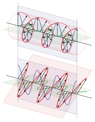
Above is circular polarization, below is vertical (blue line) and horizontal (red line). For satellite communications, vertical / horizontal or left / right circular pairs are used.
What is the use of polarization? And the fact that it allows you to DOUBLE the used frequency range, if in our Ku band, according to the frequency distribution from the International Telecommunication Union, aka ITU), you can use only 500 MHz (from 14000 to 14500 MHz), then if we use 2 polarizations, we can already have 500 MHz in each and we get 1000 MHz in total. For example, on the Yamal-200 satellite in the Ku-band there were only 6 72 MHz transponders operating in only 1 polarization, and on the Yamal-300K (which was supposed to replace the Yamal-201 in the 90 degree position) there were 12 such transponders ( 6 in the horizontal and 6 in the vertical) and, accordingly, the income of the Operator (Gazprom Space Systems) from the sale of the frequency resource doubled.
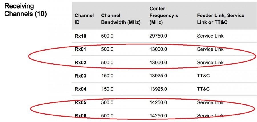
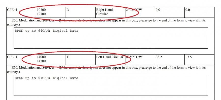
If we look at Starlink, then they also understand the importance of this and, judging by the table below, in the year 20 they declared to the FSS that they want to use both polarizations in the entire possible frequency range of 2000 MHz in right and left circular polarizations (Rx01 and Rx02 have the same frequencies, but different polarizations).
And then, with a spectral efficiency of 5 bits / Hz (a lot, but theoretically achievable with very good antennas and a large signal-to-noise ratio), we get the bandwidth of one satellite 4000 MHz x 5 bits / Hz = 20 Gigabits.
However, as always there is a BUT! Let's see how this is implemented ...
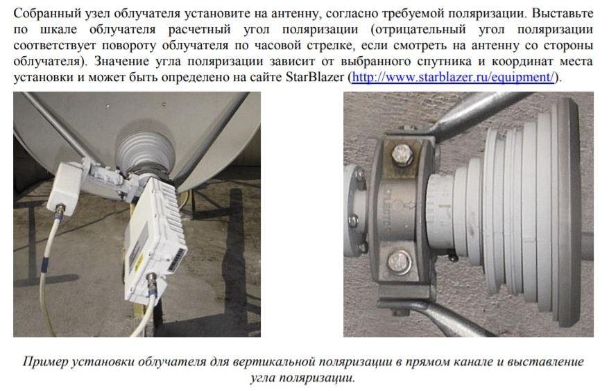
If we have a conventional parabolic antenna, then the polarization is set by rotating the feed and its waveguide around the axis to the antenna:
// In general, the polarization parameters are taken from the regulations of the company providing satellite resource lease services (for example, the RSCC regulations).
The polarization angle depends on the exact coordinates of the VSAT installation site and is determined in special programs. You can get it from the operator of the NCC (Network Control Center, usually in Moscow), giving him the coordinates.
After tightening the azimuth and terrain angle
bolts : Loosen the bolts on the transceiver mounting support (ODU).
Rotate the ODU to the polarization angle obtained in the calculation program and proceed as follows.
After confirmation from the operator that the parameters meet the standards and the azimuth and elevation are adjusted normally, it is necessary to make an additional adjustment of the polarization.
:
·
· / , .
·
· , , , 3 .
And this is a very time-consuming operation, especially when the installer is sitting on the roof in frost, because it is almost impossible to “catch millimeters and degrees” in mittens, and communicates with the NCC operator on the Iridium satellite phone (1 minute = 1 dollar) ... But the main thing is that polarization depends from the distance to the satellite and for phased array antennas (angle of inclination of the beam relative to the plane of the antenna).
To be fair, it should be noted that there are no such difficulties for circular polarization, there you just need to choose the correct position of the diplexer, for which there are two options - Left and Right, differing by 90 degrees.
A diplexer is a passive device that implements multiplexing in the frequency domain. Two ports are multiplexed onto a third port. The signals on ports 1 (to receiver) and 2 (to transmitter) occupy non-overlapping frequency bands. Therefore, signals on 1 and 2 can coexist on port 3 (from the antenna) without interfering with each other.
Now back to SL.
1) First moment phased array antennas have poorer cross-polarization isolation than classical parabolic antennas. For parabolic antennas, the standard is 29..30 dB, and for HEADLIGHTS, as I was told by the pros in this area, 26-28 dB is considered very good when working on a geostationary satellite and when an object is moving at speeds of 30..80 km / h ...
2) In the case when your distance to the satellite and the angle of inclination are continuously changing at high speed, it is very difficult to adjust the cross-polarization isolation (CRC) with the required accuracy. Even parabolic antennas on ships have the sin of the fact that the CRC sometimes "flies" and the terminal begins to interfere with the channel in a different polarization. And the ship, as you know, moves a hundred times slower than the satellite.
Alas, none of the manufacturers of FAR ESA (Phased Electronically Beam Controlled) antennas has yet published data on the actual cross-field decoupling when working with satellites in a low orbit of 500+ km.
In the case of Starlink, the polarization problems are an order of magnitude more complicated.
Here, the PAR antennas are located at both ends of the satellite channel - both on the satellite and on the ground. In addition, not only the distance to the satellite changes continuously and very quickly, but also the angle of inclination of the beam relative to the antenna plane ...
With all the genius, hard work and available budget of the engineers who were attracted by Elon Musk to create his terminal, it seemed to them 2 years ago that it would not be possible to use two polarizations, and SpaceX sent a request to the FSS that its ground terminals would be used only 1 (one) polarization - Right on the line from satellite to terminal and Left in the direction from terminal to satellite ...
That is, SpaceX had to voluntarily give up 50% of the Starlink network bandwidth, which was allocated to it by the FCC to operate its subscriber terminals ... We
also note that in the Ka-band, which is used in Starlink to transmit information from Earth to space, this problem not at all, since parabolic antennas are used both on the satellite and on the Earth, for which the cross-pole problem is solved by conventional methods, and from the gateway to the satellite it is still possible to transmit 4000 MHz in total in 2 polarizations ...
Is it possible to fix something here in the future ?? Theoretically, it is probably possible (especially since paper will endure everything, any fantasies ...). But any decision here will affect the geometry, parameters, possibly materials and construction of the terminal and its phased array. At the same time, remember that the main goal is to reduce the cost of the terminal. And the terminal has already been designed and is in serial production ...
What can be done ?? To answer this question, you need information about the actual size of the cross-polarization junction.
Unfortunately, while the Starlink terminal gets into the hands of more and more Locksmiths or IT specialists, who break it or look at what kind of Wi-Fi is there ... No one has yet guessed (could not remove the frequency characteristics of the terminal) at what frequencies it works, what modcodes, what kind of crossover isolation, what kind of interference it puts in a different polarization. These measurements are not easy - you need 2 spectrum analyzers at 14 GHz (once they cost tens of thousands of dollars, how much I won't say now, but still not cheap), a parabolic antenna with an electric drive, and a non-standard controller that can tune in and accompany a signal of an unknown format (ordinary controllers sharpened for the "television" signal format DVB-S2, but not the fact that Starlink uses it) to simultaneously measure the signal from the satellite in both polarizations, but I hopethat within six months, one of the satellite companies in the US will do it, and the information will be leaked to the Internet ...
What are the possible options ??
- If the interference in a different polarization is relatively small, use terminals with a high gain, for example: parabolic antennas with a diameter of 1 meter or more. In this case, the obstacle is simply to reduce the "working" modcode - work efficiency. For example, if the SL will use large enough electric terminals for the seas and oceans, then this problem will not be very critical there.
- In principle, do not use this polarization, but switch the entire possible resource available in the Ka-band 4000 MHz to Ku using frequency reuse or frequency reuse technologies:
What is frequency reuse? This technology is actively used in satellites HTS (High Throughput Satellite). It is enough just to split our 2000 MHz in one polarization into 4 bands of 500 MHz each (we will designate them in different colors)
(To be more precise, judging by the description of the terminal, the frequency range for Starlink is not divided into 4 colors, but into 8, since the channel from the satellite down is 240 MHz wide and 8 channels will fit into 2000 MHz, but these are details. In this case, each beam (spot, zone of consecration on Earth) has its own frequency range, which does not overlap with another beam with the same frequencies, that is, there is no mutual interference.
And most importantly, in this case Starlink can use all 4000 MHz transmitted c / to the Ka-band gateway satellite
What solution did SpaceX choose: the ability to work simultaneously in 2 polarizations or to refuse one and use frequency reuse, we cannot yet say.
The frequency filing of both polarizations with the FCC is just an administrative and legal measure, so SpaceX reserved the right to use them and canceled the ability of other operators to file a complaint against it for having a broadcast interfering with that polarization.
The answer to this question will be knowing how many beams a satellite can simultaneously broadcast to Earth 8 or 16 (or even more, because formally the antenna on the satellite can transmit narrower beams, not only 240 MHz wide, but also 120 MHz and 60 and 30 and even 15 MHz).
There is also no answer to the question whether such channel switching is possible on the satellite to use all 4000 MHz, because if the answer is negative, the Starlink network will not be able to use half of the satellite resource available to it ... And this situation, most likely, cannot be corrected before the launch of new satellites generation (if we assume that in general it is theoretically and practically possible to create a PAR with a CRC of 29..30 dB) ... And half of the frequency resource for areas with high demand for Starlink services is half of the income ...