In light of the recent discussion , the need has arisen to take measurements and obtain a numerical answer to the question: which is better? WAGO, screw terminals or copper-aluminum strands?
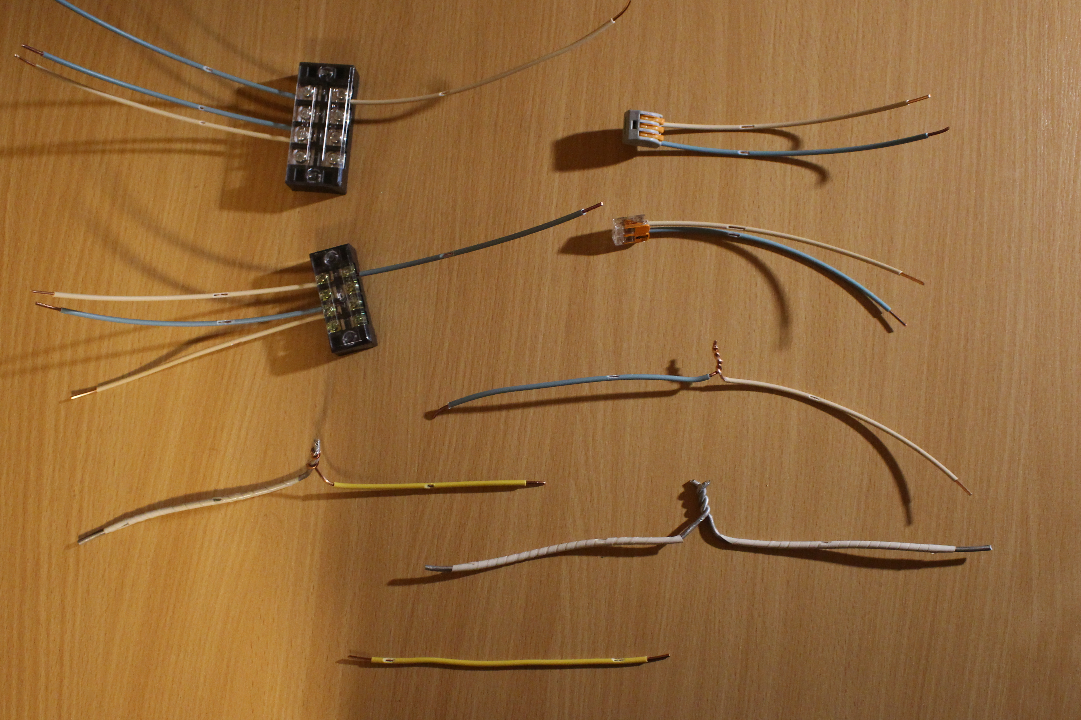
Samples
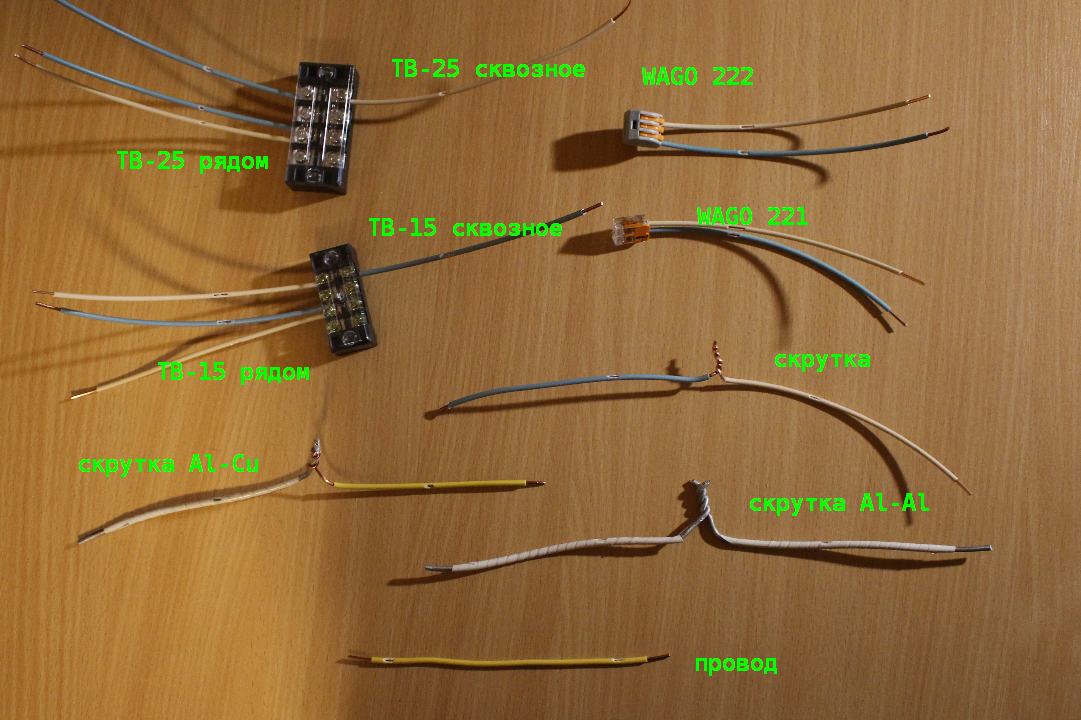
The study included:
- terminal block TV-2504L 25 A (manufacturer not specified)
- terminal block TV-1504L 15 A (manufacturer not specified)
- WAGO 222 20 A (gray)
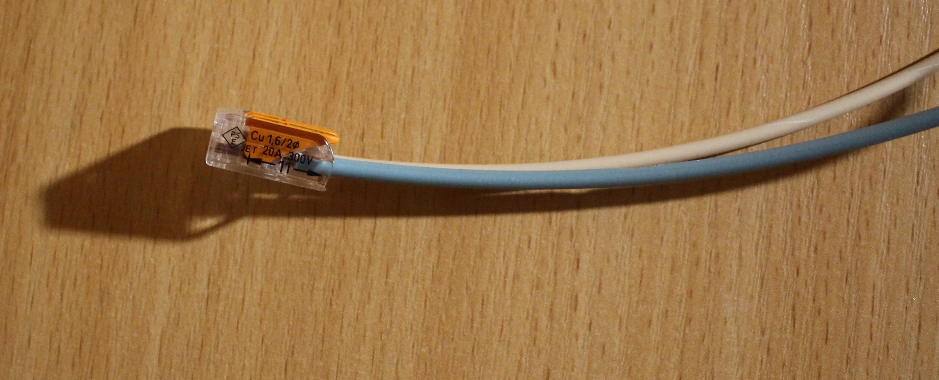
- WAGO 221 20 A (transparent)
- twisting (slightly less than 20 mm of wire)
- "Polyethylene" terminal block 5 A (not shown in the photo)
- whole wire
- twisting copper with aluminum
- twisting aluminum with aluminum
In all cases, a single-core copper wire with a nominal cross-section of 2.5 sq. Mm and an actual 2.3 sq. Mm is used. Yes, copper is often not reported in wires (I will not indicate how such people should be called). The deficiency was revealed both by measuring the diameter and resistance of the wire.
The cross-section of 2.5 sq. Mm is chosen because, based on the inscriptions on the WAGO case, this is the only cross-section supported by the terminal.
1.5 sq. Mm - too thin - diameter 1.4 mm. 4 mm2 - too thick - 2.3 mm. Such a limitation is additionally upset by the fact that according to table 1.3.4 of the PUE, the maximum current for a two-wire 2.5 sq. Mm is 25 A, and the terminal is only 20 A.
There is a problem with the aluminum wire. The available wire with a cross-section of 6.1 sq. Mm is not equivalent to copper 2.5 sq. Mm in current load (tables 1.3.4 and 1.3.5 of the PUE), which makes direct comparison impossible. For this reason, the measurement results are not included in the summary table. But not scary. In any case, the purpose of the experiment was to test copper connections, and aluminum strands were added as shock content.
TV terminal blocks are used in two ways: through - the wires are clamped from different sides and joint - both wires are under one washer, but without direct contact.
Resistance The
easiest way to characterize the quality of an electrical connection is its transition resistance. To determine this, the following "installation" was assembled
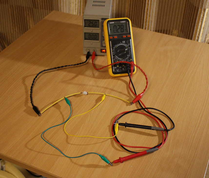
Here you can see the "polyethylene" terminal block missing in the first photo.
The junction resistance is determined by passing 2.5 A of current and measuring the voltage drop. To connect a voltmeter at a distance of 5 cm from the wire inputs to the terminal blocks, cuts are made in the insulation. Further, in accordance with Ohm's law, R = U / 2.5.
For comparison, the resistance of a whole wire 12 cm long (between the connection points of the voltmeter) was measured.
Heat
To check the behavior of the connections in practical conditions, the temperature rise over the environment was measured after a three-hour stay under a current of 15.5 A. The measurement was carried out with a thermocouple pressed against the wire core at the point of entry into the terminal block. Since WAGO's wire insulation is inserted into special grooves, the measurement was carried out inside the case. The twist, for plausibility, was wrapped in blue electrical tape - the temperature was measured under the electrical tape.
The "polyethylene" terminal block appeared after dismantling the installation and did not get into the experiment either.
Installation diagram
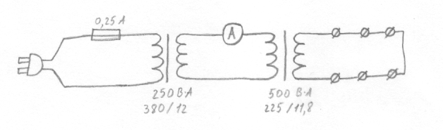
If you look closely, you can see that the entire circuit is one short circuit plugged into an outlet. But the low output voltage (0.4 V) and parasitic resistance of the transformer windings limit the current to less than nominal values.
Practical implementation of the circuit

Pay attention to a bunch of burnt fuses.
results
| R, mΩ | T | |
| TV-25 direct | 1,3 | + 10º |
| TV-25 near | 1.0 | + 9º |
| TV-15 direct | 1,3 | + 11º |
| TV-15 near | 1.0 | + 11º |
| WAGO 222 (gray) | 1.4 | + 11º |
| WAGO 221 (transparent) | 1.4 | + 12º |
| twist | 1.1 | + 9º |
| "Polyethylene" | 1,2 | - |
| the wire | 1.0 | + 10º |
| soldering | 0.9 | - |
The temperature difference is on the border of the thermometer's resolution (1º) and depends little on the resistance of the contacts. The latter indicates that it is mainly the wires that are heating up, and not the places of contacts. It seems that the oversized terminal blocks (and twists) cool the contact point.
At a current of 15 A, there is no significant difference between the connection methods.
All specimens are stored in a flower pot (without soil) on the balcony, where it is not only damp, but also wet, the daily temperature difference is about 30º, and the annual temperature is 70º. If I don’t forget in a year, I’ll investigate the issue of weakening contact with time.
Addendum: Marking of WAGO Cross-Sections
Upon closer inspection, it was found that the statement about supporting only 2.5 sq. Mm cross-sections was not true.
Taking into account some contradictions between the inscriptions on the body ("Cu 1.6 / 2⌀ 24-12AWG") and the information on the website , the supported range is 0.2..2.5 (4?) Sq.mm.
Addendum: WAGO current marking
Two currents are indicated: 20 A according to UL 1059 and 32 A according to IEC 60664-1.
UL 1059 is the standard for terminal blocks. The heating test method is described to determine the rated current.
IEC (GOST R) 60664-1 - insulation standard - does not contain guidelines for determining the rated current.
Addition: Soldering The
wires are soldered for 25 mm. No twisting. No direct copper contact.
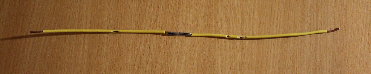
Resistance 0.9 mOhm, which is less than that of a whole wire.