Hello!
During my work in the aircraft industry, my colleagues and I have accumulated a lot of experience in the development and creation of semi-natural modeling stands for aircraft onboard equipment (Hardware-In-the-Loop, HIL) and rapid prototyping stands (Model-In-the-Loop, MIL). This publication is an attempt to summarize our experience in one publication. The resulting text turned out to be quite detailed, but the hand does not rise to cut something. In addition, when shortening in places, a causal relationship may disappear. So, it will be explained here:
- About the tools used to automate the development of the stand and its support;
- On the software and hardware of the simulation complex;
- Approaches to the construction of the HIL and MIL stands;
- On various techniques that speed up the creation of a stand and simplify its modernization and operation.
Who cares - welcome to cat.
Background to the issue
We are a group of engineers with extensive experience in the civil aircraft industry.
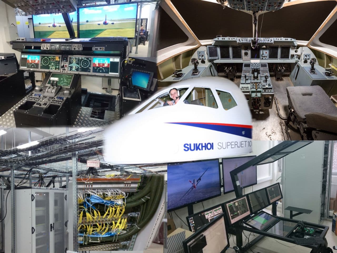
We are working on the creation of onboard equipment, stands, simulators for SSJ-100 Sukhoi Superjet, MC-21, DA-42T, L-410UVP-E20 aircraft.
From the very first stand, we were faced with a lack of guidelines for those who are going to build a test stand with tens of thousands of wires, hundreds of thousands of signals and a constantly changing structure. Due to that old longing for knowledge, my colleagues and I decided to share our best practices - what if someone is walking along our favorite rake right now?
As we see it today, any stand has the following features:
- Stands consist of equipment - test object, cable network, simulation complex, software for the simulation complex;
- Optionally, such devices as a mock-up of a cockpit, a visualization system, control loading systems, etc .;
- The test object is constantly changing as the product develops;
- Testing requirements are constantly changing;
- The technical assignment for the stand does not contain all the requirements, most of the functionality will have to be completed on the fly;
- For a test bench to be truly useful, it must change faster than the test object.
Facing the volatile nature of the test site led us to realize that:
- All "iron" parts of the stand (cable network, cockpit layout, etc.) should be easily modified;
- The architecture of the imitation complex, the structure of models and simulators should also be easily modified and controlled;
- You cannot do without tools and development environment;
Therefore, we will begin our presentation with a description of the development tools and architecture of the simulation complex.
Part 1. Development tools
In this section, we describe two of the three main tools: dBricks software and the ADS2R4 simulation software environment. The third element of the tool chain, Simulink, probably does not need to be presented and described. It is also important to mention that these three products, if handled correctly, can be closely integrated with each other and simplify most of the stand development processes.
- dBricks is a Russian software tool for the developer of the avionics complex , developed by PIRSS LLC
- ADS2R4 - environment of the simulation complex, developed by TechSAT
dBricks is used for:
- Development of protocols for information interaction of on-board equipment - test object;
- Automated formation of the architecture of mathematical models;
- Development of design documentation for the cable network of the stand;
- Automated generation of configuration files describing the inputs and outputs in the format of the ADS2R4 simulation complex environment.
ADS2R4 is a real-time test and simulation runtime specifically designed for the development, testing and validation of an avionics architecture that meets both integrity and versatility requirements.
About dBricks tool
dBricks is the primary tool used to accelerate the development and integration of complex avionics. The tool is a database for processing the following design data:
- Communication protocols;
- Structural and conceptual diagrams;
- Connection diagrams and tables;
- Assembly drawings and harness tables;
- Requirements specifications for software developers.
The tool provides the following benefits:
- A single tool for working with data guarantees the compatibility of all work results;
- The multiuser interface allows a large distributed development team to work simultaneously;
- Built-in control of connections and software configurations;
- Automated data output in the form of various reports, tables, diagrams, documents and files in a human-readable format;
- Automated data output in machine-readable format, including for the configuration of the ADS2 system, network equipment;
- Interaction with other CAD systems if necessary.
It is clear that the format of automatically generated files is adapted to the requirements of the project.
The dBricks tool itself has API access functionality that can be used to generate custom scripts for generating documents, and can also be used to fill and update the content of the database.
Using dBricks guarantees stand developers:
- Fast automated generation of ADS2 configuration files, which will not contain 100% manual copying errors (“human factor”);
- The stand cabling can be developed based on the data on the on-board cabling of an object (for example, an aircraft) stored in dBricks.
Details of the architecture of the dBricks tool
dBricks .
. :
. 1:
. , , .
. 2:
, , : , , .. , .. , . — . , dBricks , , :
, , .. - «» .
dBricks . . .
, . . . .
. :
– . , . , , ( ):
. 3:
dBricks
dBricks .
. :
- ;
- , , ARINC 429 27;
- : , , ;
- ().
. 1:
. , , .
. 2:
, , : , , .. , .. , . — . , dBricks , , :
- ;
- .
, , .. - «» .
dBricks
dBricks . . .
, . . . .
. :
- ;
- – , ;
- – , , , , ;
- – , , , ..;
– . , . , , ( ):
- dBricks , , ;
- , .. ;
- , . , , , . , , : , , .;
, , (, 32 , 64 ) (, , ). . . - , , , ;
- () (). ( ) ( ).
. 3:
About a simulation complex based on ADS2
ADS2 is a comprehensive, highly adaptable software environment and real-time hardware platform for prototyping, integration, testing, validation and verification of avionics in the aerospace industry, developed by TechSAT.
The basic structure of the ADS2 system includes the following components:
- The hardware part, which includes specialized AWPs (based on Windows or Linux), I / O boards, communication line switching devices (including control of the OI connection ), etc.
- The ADS2 Core software environment is a distributed real-time system that integrates all ADS2 components.
- Inherent low-level hardware support software such as device drivers running on the ADS2 core.
- The ADS2 graphical shell module is a service that allows the operator to control the ADS2 system in real time.
That is, the minimum mandatory composition of the ADS2 system includes the ADS2 software core (real-time computer and control workstation), an arbitrary set of standard components (such as input-output boards and corresponding drivers) and additional modules and expansion systems required by the customer.
About ADS2 equipment
A typical ADS2 system consists of the following main components:
- ADS2 ( Windows Linux). ADS2, , , ADS2.
- , - . :
- ( ADS2)
- - , AFDX, CAN, ARINC 429, MIL-STD-1553 (), RS-485, Ethernet ..
- - - (FAST) , Ethernet (TCP/UDP).
- «Timemaster» ADS2.
The basic ADS2 system is easily scalable from a small desktop system to a large distributed system. If it is necessary to increase the functionality or change the configuration of the ADS2 system, it will not be necessary to change the software of the system itself due to the use of a homogeneous hardware and software environment in it. It is very important to consider this at the very beginning of the stand creation. In our experience, during operation, the need to change the system configuration occurs at the most inopportune moment, so do not underestimate this aspect.
ADS2R4 Environment Architecture Details
ADS2.
. 4: ADS2
:
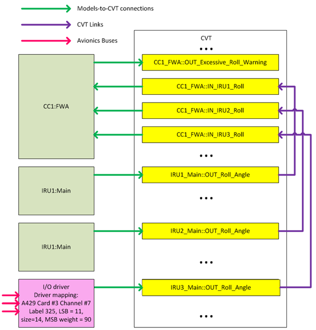
CVT – , , , ( ADS2). CVT — , , . CVT CVT — , . CVT , , . :
, CVT, , . CVT , A B. , , , - A, B . A B ; (, , ). , CVT, ( ) . - .
, , . . ADS2 , . CVT, , : , , , , , .
ADS2 CVT . - CVT, - .
. 5: CVT
ADS2 ( .. ) - (I/O channels). . CVT. CVT - ADS2. (I/O map configuration). ADS2 /:
- :
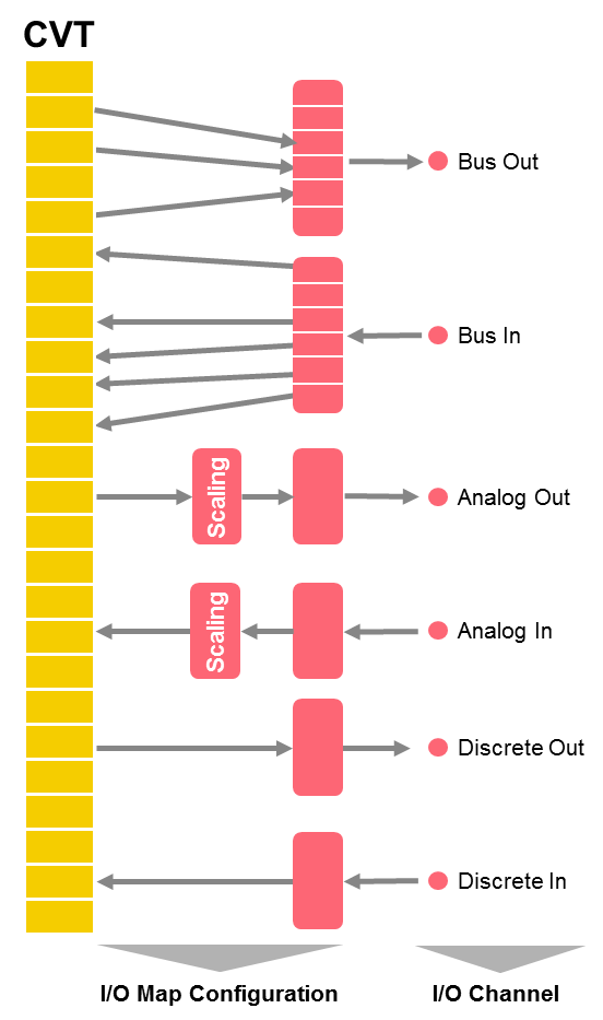
. 6: - ( )
- , CVT . :
dBricks , ADS2:
CVT dBricks.
CVT .
: «Flight Warning Application» «1» :

. 7: CVT
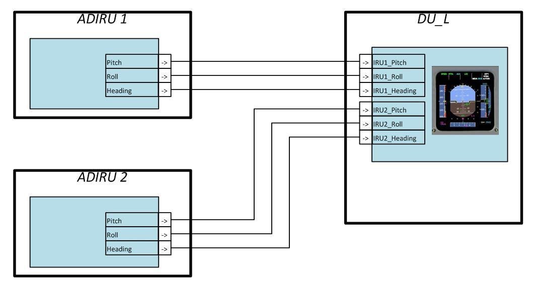
CVT dBricks. , «In_IRU1_Roll» «Flight Warning Application» «Out_Roll_Angle» «Main» «IRU1»:
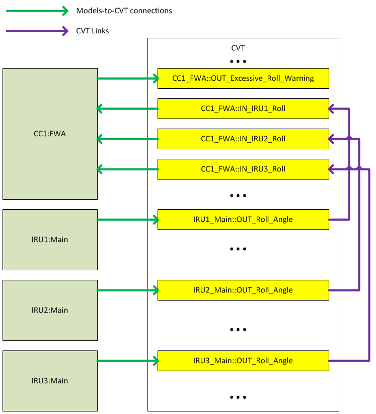
. 8: CVT
/ « » dBricks. , Out_Roll_Angle ARINC429 325, BNR ( ), 11, 14, 90, , 10. -.
. 9:
, dBricks , ADS2, -, 1 .
CVT CVT. .
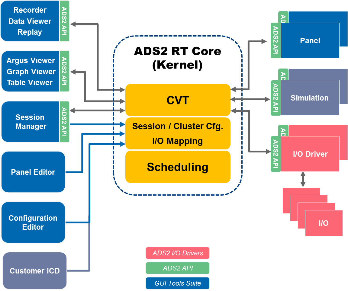
ADS2
ADS2.
. 4: ADS2
:
- ADS2 RT Core – , ADS2. ADS2 « » (Current Values Table, CVT) . ADS2 , ADS2 .
- - ADS2 – - , ADS2. - ADS2.
- ADS2 GUI Tools Suite – ADS2, , , , ADS2. : , , ..
- ADS2 API – API , ADS2 -.
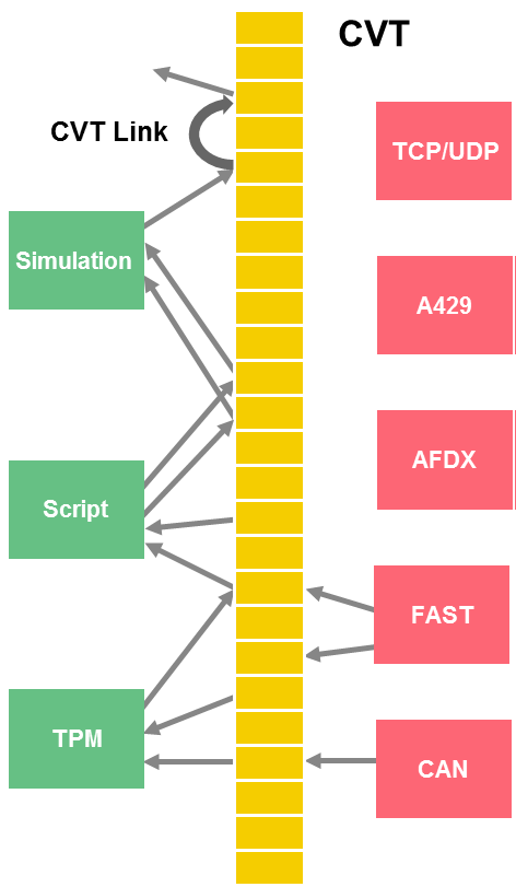
CVT
CVT – , , , ( ADS2). CVT — , , . CVT CVT — , . CVT , , . :
- – integer, floating point, string, ;
- – sampling queuing (FIFO);
- – , , , , integer strings.
, CVT, , . CVT , A B. , , , - A, B . A B ; (, , ). , CVT, ( ) . - .
, , . . ADS2 , . CVT, , : , , , , , .
ADS2 CVT . - CVT, - .
. 5: CVT
-
ADS2 ( .. ) - (I/O channels). . CVT. CVT - ADS2. (I/O map configuration). ADS2 /:
- ARINC 429, AFDX, CAN, MIL-STD-1553 (), .. ;
- RS-232, RS-485, RS-422 ..;
- ;
- ;
- Ethernet.
- :
- (, 16- - : );
- (, CVT , CVT, ).
. 6: - ( )
- , CVT . :
- AFDX (ARINC 664);
- ARINC 429;
- CAN (ARINC 825);
- MIL-STD-1553 ();
- ;
- ;
- (RS232, RS422, RS485);
- RVDT/LVDT;
- ;
- , .
dBricks ADS2
dBricks , ADS2:
- CVT;
- CVT;
- -.
CVT dBricks.
CVT .
: «Flight Warning Application» «1» :
- In_IRU1_Roll ( №1)
- In_IRU2_Roll ( №2)
- In_IRU3_Roll ( №3)
- Out_Excessive_Roll_Warning ( )
. 7: CVT
CVT dBricks. , «In_IRU1_Roll» «Flight Warning Application» «Out_Roll_Angle» «Main» «IRU1»:
. 8: CVT
/ « » dBricks. , Out_Roll_Angle ARINC429 325, BNR ( ), 11, 14, 90, , 10. -.
. 9:
, dBricks , ADS2, -, 1 .
CVT CVT. .
How Simulink is Used in ADS2
Simulink is a powerful software tool widely used in the aerospace industry. The ADS2 system implements a convenient and understandable interaction with Simulink for the development of computer models of components. In combination with the use of dBricks for storing data of communication protocols, it is possible to create an integrated chain of tools that significantly speeds up the development and debugging process.
Simulink and ADS2 Integration Details
Simulink ADS2 :
, C++, Windows, Linux. , Windows Linux, .
Simulink :
. , () ( ) . , ( , , ..) . ADS2 . , . Simulink ADS2, . Simulink ADS2, ARINC 429 . , , , (). , , Simulink ADS2. , Simulink Windows, , , , .
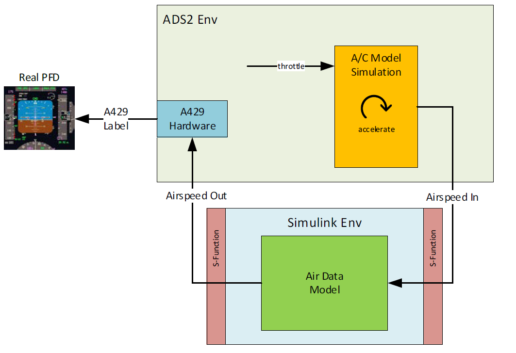
. 10 Simulink ADS2
- ADS2 CVT ADS2, Windows;
- CVT ADS2;
- ADS2 API C++;
- Simulink C++ (S-);
- S- - ;
- S- Simulink.
, C++, Windows, Linux. , Windows Linux, .
Simulink :
- Simulink;
- ( ) S- Simulink;
- - S- . ADS2 S-;
- Simulink. , , S-;
- ADS2 Simulink;
- ;
- C++ Simulink;
- C++ Linux;
- .
. , () ( ) . , ( , , ..) . ADS2 . , . Simulink ADS2, . Simulink ADS2, ARINC 429 . , , , (). , , Simulink ADS2. , Simulink Windows, , , , .
. 10 Simulink ADS2
Part 2. Stands
Stand for semi-natural modeling of the onboard equipment complex (HIL Testing)
In accordance with the requirements of the program, the stand can solve one, several or all of the following tasks:
- Support for the development of avionics;
- Comprehensive testing of on-board equipment, including tests in a closed loop with a pilot, interaction with simulators of on-board equipment, imitation of aircraft flight dynamics and external conditions;
- Carrying out an initial assessment of the operation of the onboard equipment by the flight crew;
- Certification tests, including tests for resistance of avionics to possible failures; work in take-off and landing modes in conditions of minimum visibility, working out modes of approaching the ground, etc .;
- Development of operational documentation;
- Training of line pilots on a technical training facility corresponding to, say, FTD level 4.
What imitation complex to use
As a simulation complex, we propose to use a solution based on the ADS2 system, since this provides the following capabilities:
- , ;
- ;
- Simulink ;
- . ;
- ;
- ;
- .
The use of a solution based on the ADS2 system is most effective when using the automated generation of configuration files (configuration tables and CVT points, system models) using the dBricks tool.
One of the most time-consuming tasks in the development of an avionics stand is the configuration of models of systems and I / O boards. With dBricks, this task takes an hour. The only thing that needs to be done is to assign which of the ADS2 I / O boards will be responsible for which channel of the simulated equipment. After that all the necessary configuration files can be generated automatically.
Typical simulation complex of a modern aircraft
| № | |||
| 1 | 3 — 6 | ADS2.
: ADS2; , ..; . |
|
| 2 | 1 | ADS2. Windows.
: ; ; Simulink ; /. |
|
| 3 | 1 — 3 | Windows . . ADS2 UDP . | |
| 4 | - (FAST ADS2) | 1 — 10 | - () |
| 5 | - | 10-40 | - . , . :
|
Integration of third-party simulators
Some system vendors are concerned about their know-how and refuse to provide the data needed to create models of their systems. Engineers are a good example. Typically, engine suppliers provide their simulators to run the stand. These simulators are usually connected to a central bench simulation system via Ethernet or in the worst case through some special interfaces such as "Reflective Memory". In any case, ADS2 can support any interface.
, . , (10-15 ) ( , ..). , , , , , , ...
The cable network is one of the most important components of any stand. The approaches and tools used to design and fabricate a cabling can have a significant impact on the design and manufacturing schedule of a stand. We use an approach that has proven its effectiveness in a number of different projects, here are its basic principles:
- , , 100% . , , :
— ;
— ; - ( ) . :
— ;
— 5 ;
— .

. 11:
- , , , ;
WAGO 2002-1871 ( ) DIN .
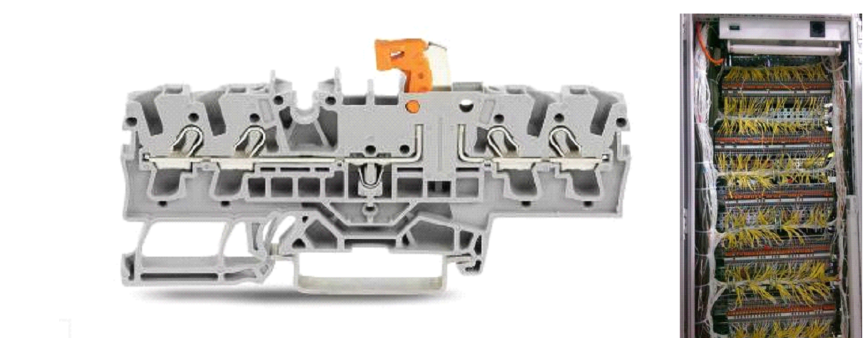
. 12: WAGO
WAGO :
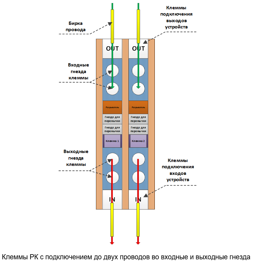
. 13.: WAGO
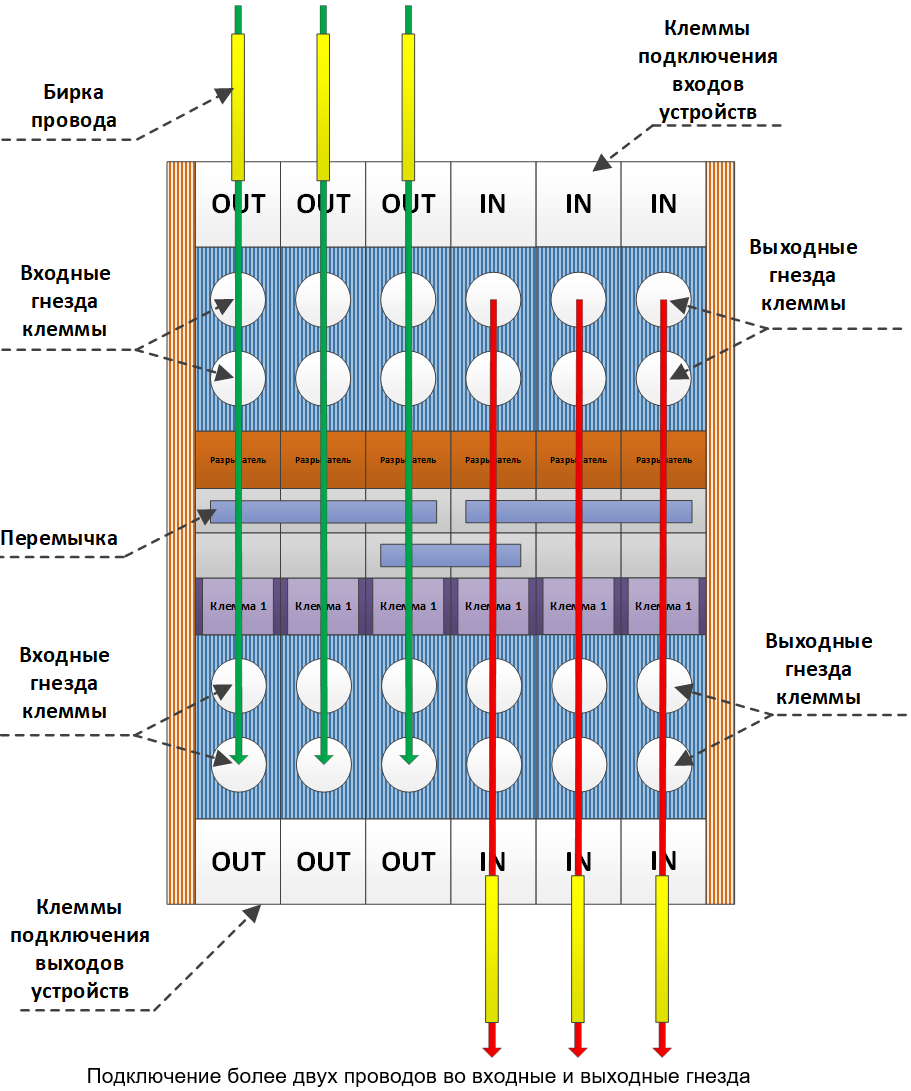
. 13.: WAGO
- . – WAGO, . – - ( ADS2). , , .
:

. 14:
- dBricks. :
— , , ..;
— , dBricks , 100% (« »);
— .
1-2 - ( ).
How to create a cockpit layout
The layout of the cockpit, as a rule, should:
- Provide a place for the installation of the equipment of the test object, normally located in the cockpit;
- Provide convenient (if possible) access to the test object, wiring of this equipment, mechanisms, etc .;
- Repeat cockpit layout;
- Repeat the view of the surrounding area from the cockpit.
The layout of the cockpit is subject to frequent changes, especially before the first departure of the aircraft, so we start the development of avionics with a mock-up of the cockpit and then move on to the final decision.
Initial cockpit layout An initial cockpit
layout can be developed from the initial cockpit view. At the same time, minor changes to the standard layout may not be applied to the original cockpit layout. At the same time, the design of the initial cab layout should provide technological access to the rear panels of the devices. Below is an example of a similar initial layout of the cockpit, it should be noted that all side panels are easily removable, and in general the structure is modular.

Figure: 15: Initial layout of the cockpit
Whenever possible, we recommend not using the raised platform, although there are at least two good reasons for using it for the layout of the cockpit:
- Some visualization systems require free space under the cab floor. To use a cylindrical visualization system, it is usually required to raise the layout of the cabin to a height of 1.2-1.5 meters. A collimator, spherical projection or visualization system based on simple monitors does not require this.
- In the case of using pedal posts or other mechanical controls, some space under the cab floor is required. In this case, the cab layout is also required to be installed at a height of about 50 centimeters from the floor level.
, . . , , , , . , ..
–
The final cockpit layout must match the dimensions of the actual flight deck to meet certification requirements. Depending on the composition of inspections and the approach of the authorities, it may be necessary to create an additional “final” cockpit mock-up that reproduces the real cockpit. For this task, it is recommended to use real parts of the fuselage with real equipment installation locations, pilot seats, etc. For example, for the Electronic Bird stand of the SSJ-100 program, a sample of a real cockpit was used, originally used for debugging an assembly line. It could not be applied in a real aircraft, since it did not meet the formal requirements of production, but it was completely suitable for the tasks of the test bench.
If you plan to use a cockpit layout as part of a simulator with a level, say FTD level 4
4 CFR, 60. 1b Table B1A «Minimum FTD Requirements – General FTD Requirements QPS REQUIREMENTS» : «The FTD must have equipment (e.g., instruments, panels, systems, circuit breakers, and controls) simulated sufficiently for the authorized training/checking events to be accomplished. The installed equipment must be located in a spatially correct location and may be in a flight deck or an open flight deck area. Additional equipment required for the authorized training/checking events must be available in the FTD, but may be located in a suitable location as near as practical to the spatially correct position. Actuation of equipment must replicate the appropriate function in the airplane. Fire axes, landing gear pins, and any similar purpose instruments need only be represented in silhouette.» .


Figure: 16: Layout of the SSJ-100 cockpit at the Electronic Bird stand
What system for imitating the external visual environment to use
There are a large number of commercially available visual environment solutions for flight simulators and test benches. Solutions range from simple displays to high-end collimator systems. In our experience, the use of a system for simulating an external visual environment may be required in only two situations:
- Using the stand as a simulator (for example, FTD level 4),
- Some certification tests.
CFR 60 Table B1A section 6.a : «The FTD may have a visual system, if desired, although it is not required. If a visual system is installed, it must meet the following criteria...». , FTD Level 4. , , 6.a.1-6.a.7 CFR 60.
Most certification tests are carried out under the worst possible visibility conditions, which generally means the application of instrument flight rules and zero visibility. The only type of certification test where the quality of the external visual environment simulation system really matters is the assessment of take-off / approach minima. Performing these tests on the bench saves 20-40 test flights. In our experience, the authorities did not require a high-end simulation system to use bench test results as a means of validation. In any case, the certification authorities should be consulted if these tests are planned to be carried out at the stand.
In real life, engineers hardly ever use a visualization system as they focus on the behavior of the equipment. Test pilots are usually satisfied with the simplest system of simulating the external visual environment. The visualization system of the external environment can be useful for the marketing activities of the company and the formation of various publications in the press.
Thus, it seems logical to choose a solution using a cylindrical or spherical projection system, which will provide:
- Field with a field of view 120x60 degrees.
- Moderate initial cost of the system and the cost of its operation.
How to place test objects on the bench
We propose to use commercially available telecommunication racks (server racks) to accommodate equipment that is normally located outside the cockpit. The only difficulty can be caused by the need to locate equipment that requires forced cooling. This problem can be solved in several ways:
- The development of a special cooling system, which is a high-pressure fan with a sound absorber and air ducts;
- Installation of simple low pressure fans in special frames under the cooled device. However, low pressure fans do not always provide the required performance;
- Installation of high pressure fans in special frames under the cooled device. This solution has high performance but produces a lot of noise;
- Installation of a special door with integrated air conditioning on a telecommunication rack, for example, Rittal SK.
How to create a power distribution system
The power distribution system is designed to distribute the power supply to the OI. It copies the SES system installed on the aircraft.
Converting 115VAC to 28VDC and 115VAC 400Hz is straightforward as there are many off-the-shelf solutions available on the market. Therefore, this is not the subject of this description.
We take the following approach:
- Initially, a special layout of the distribution system is used;
- Before the start of certification tests, the mock-up is replaced with a real distribution system.
The initial layout of the SPP is done using commercially available components such as WAGO clamps, relays, fuses, etc. All of these devices are mounted on a DIN rail or similar easily accessible surface. The diagrams for all connections must repeat the "real" SES of the aircraft. Solid state switchgear can be used right from the start. SES of a real aircraft, as a rule, is subject to multiple changes and updates, especially in the early stages of design. All of these changes can be implemented much easier using an easily modifiable layout than “real” compact aircraft switchgear.
The layout of the distribution system may be replaced with a real sample prior to certification testing.
Rapid prototyping stand for airborne equipment (MIL Testing)
In accordance with the requirements of the program, the stand can solve one, several or all of the following tasks:
- Assessment of flight control laws;
- Preliminary assessment or layout of dashboards (indicators, controls);
- Debugging of information exchange flows of equipment;
- Assessment of hardware requirements prior to their transfer to the departments responsible for hardware production and software development;
- Carrying out early assessments and checks of system fault tolerance.
What imitation complex to use
As a simulation complex for the rapid prototyping stand, we propose to use a solution based on the ADS2 system for the same reasons as for the semi-natural simulation stand.
Typical imitation complex of the stand:
| № | |||
| 1 | 1 | ADS2.
:
|
|
| 2 | 1 | ADS2. Windows.
:
|
|
| 3 | 2-3 | ADS2. Windows. , | |
| 4 | 1 | Windows . . ADS2 UDP |
How to develop mathematical models
Any test bed evolves as the project progresses. Hence, no one can offer a "complete" or "best" set of development models. For a Rapid Prototyping Stand to be useful throughout the life of a project and still require a reasonable investment, you need to be flexible and try to use a Pareto-style approach. However, we will try to provide examples of an “initial” and “extended” set of models to illustrate the average case.
The initial set of models in our example is designed to support the following work:
- Development and verification of laws for testing control systems;
- Demonstration and verification of the initial layout of the PFD indicator .
During the initial testing phase, there is no need to implement complex flight control electronics models that include redundancy, reconfiguration, delay, etc. There is no need to test complex applications like FMS . Therefore, the following preliminary list of models can be used:
Preliminary list of models
| № | ||||
| 1 | Simulink | . , , XPlane, . Simulink . | ||
| 2 | Simulink | , , . | ||
| 3 | Simulink | . | ||
| 4 | Simulink | , , (, ). | ||
| 5 | Simulink | ( ), | ||
| 6 | Simulink | , . | ||
| 7 | PFD simulation | C++ Python | , , , , TAWS TCAS |
An "advanced" set of models should support the following works:
- Advanced checks on flight control laws including redundancy, delay, fault handling, etc .;
- The ability to check the laws and logic of the autopilot control;
- Complete simulation and assessment of the cockpit information environment including PFD, ND , FMS, CAS messages , synoptic pages and controls;
- Debugging of information exchange flows of equipment, including analysis of the path of each parameter from the source to the end user;
- Analysis of the consequences of failures;
- Validate software requirements prior to moving to the labor intensive software development phase in accordance with DO-178.
As a result, the list of final models is much longer. The list below is neither complete nor accurate. However, we believe it can provide an indication of what remains to be done.
Advanced Model List
| № | ||||
| 1 | Simulink | |||
| 2 | Simulink | , , , , FAA. | ||
| 3 | Simulink | . | ||
| 4 | Simulink | , , . | ||
| 5 | Simulink | , , . . | ||
| 6 | Simulink | , : . | ||
| 7 | Simulink | : ADC, IRU, GPS, VOR, DME, RA, ILS . . | ||
| 8 | Simulink | , : , , , , , , , , .. | ||
| 9 | Simulink | , , , . | ||
| 10 | C++ Python | PFD, ND, FMS, TAWS, CAS, , CAS .. , , , .. | ||
| 11 | C++ Python | |||
| 12 | C++ Python | - , , / , .. | ||
| 13 | Simulink, C++ Python | :FWS, DCA, SWS, CMS . |
For a smooth transition between the initial and extended set of models, the following criteria for modeling systems must be met:
- Scalable architecture of modeling systems;
- Using tools to manage the configuration of data streams;
- Automated generation of interface model configurations. Should include mostly I / O portions of Simulink models and portions of I / O code for models developed in C ++ or Python;
- Configuration control system.
It should be noted separately that if the same architecture is used for rapid prototyping stands and for semi-natural modeling stands, then many of the above models are developed once and can be easily reused as part of any of the stands.
How to create a cockpit layout
Typically, we used the following approach for the MIL booth layout:
- All avionics, including indicators, control panels, etc. modeled on commercially available touch screen monitors. The touch control functionality is mainly needed to interact with remotes;
- , ( ), , ;
- VESA.
- .
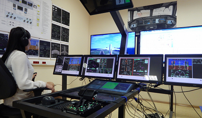
. 17
The design of the stand is very simple when you understand why this or that decision was made. This material was created on the basis of many years of work, as well as the experience of applying successful and unsuccessful technical solutions.
Right now we are actively involved in the creation of a semi-natural simulation stand for a small aircraft. For this project, it was proposed to use a new domestic development of RHYTHM produced by the company of the same name as the basis of the simulation complex. We have no experience of working with RHYTHM, but everything happens for the first time.
Here's what we currently know about this decision:
- RHYTHM cost is guaranteed to be lower than ADS2 from TechSAT;
- There is no ready-made solution in case of scaling the system, but we already have ideas on how to quickly do it if necessary;
- Inevitable childhood illnesses are compensated by the developer's prompt technical support.
Based on the results of our work, we will definitely share our experience of using RHYTHM in a real project.