Not being able to purchase a ready-made device in a case from the manufacturer yet, I decided to install Laurent-5G into the case myself. Having searched for such a body on the Internet, I was once again convinced of the complete lack of taste and ability to design such products from domestic manufacturers, having once again envied the proposals of Chinese suppliers.
Well, who, pray tell, might outwardly like such rough and heavy cases for radio electronic equipment, which are most likely a legacy of the Soviet past, but are still sold in the present?
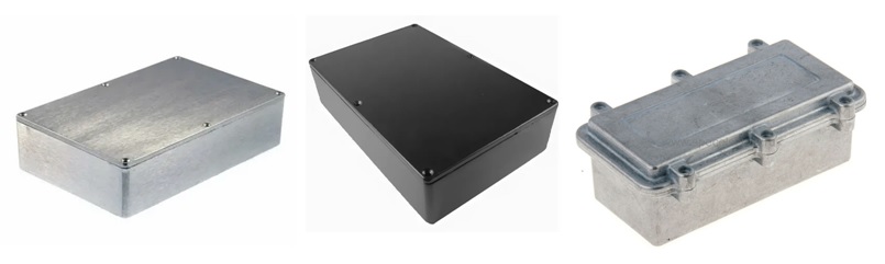
Photo of "prehistoric aluminum crocodiles"
Good cases from an aluminum profile in Russia are made only to order in large quantities, which is not at all necessary for a private person. And yet I decided not to order a case on AliExpress (it would take too long to wait for an order), but to buy it in Russia and accidentally found a suitable case in Omsk (https://danomsk.ru/), where the supply of a similar one is probably better than in Moscow. products from China. At the same time, the cost of the case was quite a bit higher than on AliExpress, which surprised me very pleasantly. So, having ordered the Chinese corps in Omsk, I received it in a week by mail.
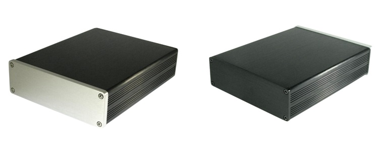
Aluminum case for amplifier (120mm X 160mm X 40mm)
Made on the basis of a split aluminum profile, the "Chinese" is by no means prettier than their Russian "brothers", isn't it? And when will our manufacturers begin to manufacture such things and supply them in pieces to the Russian market?
Now it remained to select the rest of the components for the finished box device. Since the dimensions of the back panel of the case are not large, during the selection I tried to minimize the components so that there was enough space for all the details:
- External case power supply 12V 1A
- GSM antenna with SMA connector
- Aluminum strip for new faceplate 40 X 2 X 1000 mm (Leroy-Merlin)
- Built-in power connector for 220V 6A loads (sold universally common for all relays)
- Industrial circular connectors Ø12 mm 3 pin block cable for outputs with relays - 4 pcs (Chip and DIP)
- Ø12 ( , elektron34.ru) — 2
- Ø3 10 () — 4
- Ø3 () — 12
- Ø0,2, 0,75 1,5
- WAGO 5- — 3
Industrial round miniature connectors with a counterpart were made of high quality, were compact and withstood a fairly decent current (5A at 220V), that is, they could switch a load of up to 1.2 KW, which was enough for me in abundance.

Round three-pin industrial connector Ø12 mm, 220V 5A, with a counterpart
Metal buttons without fixation did not have a light indication, but they were also compact (Ø12 mm, length 20 mm), were pleasant to the touch when pressed, contact bounce was minimal (which by the way is able to suppress the logic of Laurent-5G).

Anti-vandal metal push-buttons without fixing with fastening of wires "under the screw"
In addition, I also bought such a set of a radio remote control with a 315 MHz receiver, so that you can control the relay of the Laurent-5G module remotely within the room: A set of a radio remote control with a 315 MHz

radio signal receiver
I decided not to use the bezel from the case (it was very good, stylish, but too thick - it was made of an aluminum plate 5 mm thick), and I carved a new one from an equally nice matte aluminum strip 2 mm thick, after which I still had its fair amount. The process took place in the garage using a conventional screwdriver with drills and a set of needle files, and of course, a workbench with a vice, and it took about 2 hours with careful execution. At the same time, all technological holes (for the RG45 Internet connector, SMA antenna, 12V power jack), as well as the fastening screws were made accurately and accurately, without unnecessary gaps. Likewise, marking and making holes for power connectors and control buttons on the "native" rear panel was made (it had an acceptable thickness). Despite the fact that in artisanal conditions,some errors were made when grooving the holes, later, when installing the components, they were covered with the rims of the latter and everything looked perfect, outwardly indistinguishable from the factory version.

Case with installed network connectors and buttons (rear view)
The Laurent-5G board itself was installed symmetrically along the width of the case and fastened to its bottom with screws through threaded rivets. Brass dowel sleeves can also be used, but the rivets are lighter and prettier. Only the heads of the hidden microscrews, which do not protrude outward, remained visible from the outside from below. And of course, the rubber self-adhesive feet included in the kit were glued to the bottom of the case.

Laurent-5G in the case (front view)

Position of the Laurent-5G board inside the case

Installing the board on threaded rivets in the corners, one can be seen on the phono
After finishing with the installation of the case components, we turn to the electrical part.
In addition to being able to control via the WEB or API, our two momentary buttons will control relays 1 and 2 using the logic rules of the CAT module. They will also be controlled by a radio remote control. The remaining relays 3 and 4 will be without pushbutton control. In principle, there would be enough space for installation for four buttons, but two were enough for me.
We connect the button contacts made "under the screw" to the screw terminals of the output lines IN1 and IN2 of the Laurent-5G module, according to the official documentation for the module , available on the manufacturer's website.
To be able to obtain a "high level" signal on the corresponding input lines when pressing the buttons, let us start the + 5V voltage from the board itself through the buttons and supply it to the input opto-isolated lines IN1 and IN2 ("dry contact"). Since the input lines are opto-isolated, in this case their isolated ground must be connected to the common ground of the module (terminals I1G and I2G are connected to the GND terminal).

Photo of the control button connection (shown with an example of the Laurent-2 module and a similar Ø21mm button)
We divide the power received from the 220V input connector as follows: divide the "phase" with a WAGO terminal block into four wires and supply it to the inputs of the corresponding relays, connect the outputs from the relay keys to industrial micro-connectors from the ChiP and DIP. "Zero" and "ground" from the input connector immediately divide each into 4 parts and give the same output "round" connectors. On the connectors, we do everything the same for everyone, symmetrically with respect to the connector locks.
Our radio remote control receiver has 4 control channels D0, D1, D2, D3. To receive a control signal from the radio remote control on the input lines of the module, the pin D0 and D1 channel terminals are similarly connected to the IN1 and IN2 lines, to which our buttons are already connected, and D2 and D3 - to the IN3 and IN4 lines. The radio receiver board needs a + 5V power supply - please, the Laurent-5G module has one and can power the radio receiver module by itself, the second wire is connected to the GND Laurent-5G common ground. We also connect the GND of the module to IG3 and IG4, in the same way as we did for the buttons.
The connecting wires turned out to be too much, but with a neat layout, everything went into the case. I can be criticized for the close and supposedly dangerous location of low-current components of the board and 220V conductors, but believe in most modern factory products (take at least the same Netping-4 SMS or Rodos-10) power and low-current components are not located at a greater distance from each other ...
I did not fasten the radio receiver to the screws, but simply glued it to the bottom of the case from the inside on a soft "double-sided tape". When the case was closed, the radio signal was weakened, but at a distance of 5 m the remote control worked stably, which was enough for my household tasks. For better signal reception, you need to place it outside the case, but then it needs a separate plastic case and a stranded connecting wire with Laurent.
I planned to use my Laurent-5G in the case at home to control the power of the router and the Wifi access point with the ability to reboot them remotely via GSM in case of possible "freezes". The power load from the router and the Wifi-point together did not exceed only 30 watts, so the case's electrician was made "with a margin".
Photos of the "finished product":

With a power supply unit and a remote GSM antenna

With a reliable reception of the GSM signal, you can use a whip antenna

. Wires were soldered to the counterpart of the output network connectors, connecting them, for example, to a 220V socket (for one load) and 220V extension cord with cut off plug for simultaneous control of multiple loads from one relay (pictured above).
To make everything work, it remains to turn on Laurent-5G, reconfigure, configure the default IP address to the address in your local network and create the necessary logical rules in the CAT Event Scheduler that connect the operation of the keyfob, buttons and relays.
A detailed description of the creation of logical rules can be found in the official manual (see the Section "CAT System").
That's all! The boxed device is ready and running.
I have a Mikrotik RBM33G router with two LTE modems connected to Relay 1. A Mikrotik wifi access point is connected to relay 2, distributing the Internet from the same router.
Due to the fact that Laurent has the ability to create a rule for the event "ping an address in the local network", and the Mikrotik router with an arsenal of its most powerful scripting LUA language allows you to write any scripts and of course can ping Laurent-5G, and both devices also have modems, then both of them can successfully "monitor the health" of each other and inform the admin about violations of this tandem using SMS messages. Mikrotik, can also inform the administrator by e-mail or in the configured chat of the Telegram bot.
For the convenience of work, events were also created in the Laurent-5G Event Scheduler to turn on / off the router and access point on a schedule at different times on weekdays and weekends, as well as relay switching rules by SMS for remote equipment reboot and informational events for reporting the status of the device and its peripherals.
Externally and functionally, it turned out to be a very good device.
The only big drawback is that with such a design, you need to know exactly where on the input socket to which the power cord of the 220V input connector of the Laurent body is connected is "phase", and where is "zero". That is, when you turn on the system, you must first arm yourself with at least a probe screwdriver. If, when turned on, they are reversed, then nothing bad will happen, everything will work, the loads will turn on and off, but not through opening the phase, but through opening the neutral wire, and the phase will remain on the output connectors, even when the relays are off, which unsafe and of course unacceptable. So at home I physically set the laurent so that my household could not independently "reverse" the phase and zero of his loads. I piled it higher on the closet. Now, at the right time,the installed ability to control the relay using a radio remote control came in handy.
Compared to analogs, the finished box device clearly lacks a built-in redundant power supply with a lithium battery to power the module. But for this, you already need a body twice as large.
To power such a system, you can use an external 220V UPS (which, in my opinion, is very cumbersome) or, by slightly changing the connection, you could use an external 12V UPS, which would power the board and provide power to small, for example, 12V loads (the same Router and wifi-points), through the same Laurent relays, especially since Laurent-5G has, in addition to the jack connector, internal screw terminals for the 12V input power. Controlling 12V loads would eliminate the 220V phase finding problem when connected.
On reflection, I decided that I could simply make an adapter cord - "male" 220V - "female" 12V jack and similar adapter cords from industrial connectors from the case to final 12V devices and apply the same 12V to the 220V input connector. In this design, the operation of the device becomes more convenient and completely safe.
In the case version, the device exists in a piece version and, I hope, the manufacturer of Laurent-5G itself - the KernelChip company - will turn out better in the end. The rest of the users have to wait for the release of the finished box product or try to do something similar on their own, not forgetting about the safety and responsibility when releasing devices of their own "manual" assembly.