- Don't forget about killswitch.
- Never break the first rule.
If these simple rules are violated, the result, at best, will be as in the video below.
In this article, I will explain how to properly configure and manage Kelly KLS controllers. How to connect Kelly controllers over UART. For example, Kelly + STM32 or Kelly + Arduino.
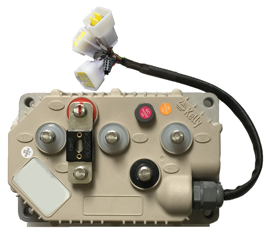
Connecting the motor to the Kelly controller is straightforward. Power cables on terminals to bolts on the body. Hall sensors to the DJ7061Y connector.

Connecting controls depends on your tasks. For example, for a buggy, we connect all controllers to a common board.

In other cases, we use a board with an STM32 microcontroller for channel mixing.
The Complete Guide to Setting Up Kelly KLS Controllers
Install the configuration program on the PC. The Android application only allows you to monitor the parameters. We connect the PC and the rs232 controller <--> usb converter.

Low volt
, bms .
Over volt
over volt . , . , bms .
Curent percent
, , , , , . . 90, 90 300 , 300 90 270 .
Battry limit
40 40 , . , . 300 , 90 270 40 108 . 110. , , , BMS.
Identification angle
, auto detect auto detect auto detect . , 170
85, 85 170.
auto detect 170, WRITE , . 85 , .
C write , write , , - , . , .
TPS LOW error ,
TPS High error. , . - , . .
TPS type. 0 5 . 2 1 4 .
TPS DEAD LOW , . speed, , . , , .
40 43 , 0 255 2.55. 42 2,55 16, , , 42 48 48 2,55 18 20 2,55 low high low dead.
Fwd map
50 50- 30 , 30 , 70 0 100.
Rev map
50 , 20. 80 .
Brake type
. 0 , 0 5 2 high . break dead High , . brake pedal , , .
MAX OUTPUT FRE
1000 , . , .
MAX SPEED
motospeed , , max speed. , , . 15000 . 3 .
THREE SPEED
, . - 90, , 1 3.
Pwm frequency
. 10 20 , 20 20 - , , , 10 . , 10 .
Startup h-pedel
This means that if the checkbox is checked and you turn on the controller at the moment when the throttle stick is pressed, then it will not go, but it will give an error that the throttle stick was initially pressed and when you release it then press it, then it will go. uncheck the checkbox, then if you have pressed the throttle stick and you turned on the controller, it will immediately rush forward, this is a protection against the fact that it does not go forward when the throttle stick is pressed while the weak point is turned on.
Brake h-pedel Brake
protection, as I understand it, when the brake is not pressed, it will give an error.
NTL h-pedel
protection of neutral gear if during engagement the neutral gear is not turned on it will give an error too some protection
Joystick
The joystick mode is used for vehicles that have an equivalent stroke like forward legs backward, for example, there is a wheelchair or some kind of trolley that can go both forward and backward. But for this mode, you need a joystick and a special throttle knob that rotates both in one and the other direction and has a neutral position that gives half the voltage at the output of two and a half volts to it by default if you twist and forward it reduces the voltage. If you turn it back and forth, it increases the joystick.
Three gears switch
switch trigger here it is written that if the checkbox is checked then you have a neutral, there is a switch forwards and backwards, it is forcibly needed so that it leaves, forward forcibly turn on the button forward to go backwards, you need to forcibly turn on the button backwards. If the checkbox is not checked, then he goes forward by default, you do not need to press anything additionally, but goes back only at the moment when the reverse button is pressed.
Boost
Let's just say to survive with the controller maximum, it gives the phase and battery current at 100 percent for a few seconds if you check the box, then you can connect the boost button and for example by pressing the boost button you kind of simulate a full press of the throttle and these parameters are battery limit and caring one hundred percent percent.
Foot switch
A very strange feature too, protection from fools or from children. I do not know an additional button to the gas pedal or the gas hook until it is pressed, the gas handle is simply not active.
Cruise
Cruise control function, if, for example, you pick up a certain speed and hold the throttle stick for 3 or 5 seconds without changing its position, then the controller perceives this as the cruise speed and, accordingly, after releasing the throttle stick, it goes at this speed by itself ... To stop, it is enough either to pull the throttle handle again, twist it so to speak, or press the analog brake all the way. Keep in mind either the usual discrete brake. Just press the button then the cruise will exit its mode.
Change direction
The controller carries out auto detect, sometimes it happens that the wheel turns in the wrong direction you want. If it rotates in the wrong direction and goes back, then in order not to change the configuration of the phases, do not do it again to detect, you just go into the program, check the box, click write and restart the controller and it just changes the direction without changing anything.

Motor mominal curr
This parameter is responsible for the nominal motor current, but only during auto-identification.
Motor poles The
number of poles, namely poles and not pairs of poles, that is, the actual number of poles of your motor. This is necessary for the correct display of the correct speed limit, but if you do not change anything here, then in principle it works too.
It will have no effect other than limitations and the display in the monitor will no longer matter.
Speed sensor type
This is the choice of let's say engine angle sensors. If there is a two, these are ordinary hall sensors, they are used in 99 percent of all motors.
Resolver poles
We don't need it since we don't use it. We have 3 hall sensors and there simply cannot be any other number. Therefore, there should be as many hall sensors as there are phase wire sensors.
Motor temp sersor A
type of temperature sensor for the motor itself. If you have one of these types that are written in blue, then you can use a hall sensor.
High temp cut
This is the high temperature at which the controller is cut off altogether. Or rather, it concerns not the controller, but the engine.
Line hall zero
The parameters that are responsible for the analog hall sensors, we just need them.

IQ kp IQ ki ID kp ID ki
Parameters responsible for the PID controller.
Brk ad brk%
Parameters for analog braking. We do not use an analog brake. If you use the same brake lever as the throttle, which changes the output voltage from the angle of rotation, then you can use and specify the maximum amount, the maximum current which is expressed as a percentage from 0 to 50.
Rls tps brk%
When the handle is released, the throttle starts to slow down. Well, on the one hand, it's like an emulation of an internal combustion engine, on the other hand, if you don't have a brake lever, you can use the parameters. For example, set the value to 15 and thus, when you release the throttle, you will have 15 percent deceleration, respectively, and 15 percent recuperation.
Ntl brk%
When switching to neutral gear, regeneration is also triggered in percentage, so I don't use 0. Regeneration everywhere can be set to a maximum of 50 percent.
Accel time
This is the acceleration time, it goes in increments of 0.1 second, that is, one means 0.1 second means 10 seconds. This is the reaction time to the throttle stick from the moment you pull it to the controller bringing it up to rated power.
Accel rls time
When you reset the throttle, the time it takes for the controller to reset power after you reset the throttle.
Brake time I set the
value for two and a half seconds and it turned out to be very convenient for me, that is, when I press the brake lever, it does not start to brake immediately, but starts to gradually increase the braking power. Power by recuperation for two and a half seconds, that is, here, too, the discreteness is 0.1 second and in 2 and a half seconds it begins to increase the braking force up to 30 percent, as indicated here in two and a half seconds.
Brake rls time
This is the regeneration reset time. Here, it is advisable to set a value smaller, that is, one so that when you release the brake, you immediately turn off the brake and not brake further.
Brake sw brk
This is the percentage of braking with discrete braking, that is, when the brake lever is pressed, I have it set to 30 percent. Unfortunately, I can no longer set it because it already breaks the views wheel. For me thirty percent is enough for it to brake very well.
Change dir brk
When you turn on the reverse, it can also start recuperation, that is, when you turn on the reverse on the go, by the way, there was even a question somewhere on the forum what would happen if you turn on the reverse on the go. Nothing will happen, at first it will be braked to zero by these five percent or 50 percent. If this value is restored, and then after a complete stop, it will start to drive from the beginning of recuperation and then move.
Kelly + Arduino. UART connection
the data structure T_Sync_Comm_Buff is used by the controller with a total data length of 19 bytes. Complete data sent to or received from a controller includes a command field, a no_bytes field, and a data field. The serial baud rate is 19200.
The command field indicates the operation. The controller response returns the same command value it received.
The no_bytes field indicates the number of bytes to be sent or received from the data buffer field, excluding the checksum byte.
The data buffer field has two parts: valid data and a checksum. Before sending data of type T_Sync_Comm_Buff, the ETS_TxMsg method creates a checksum and places it in valid data points. After receiving complete data from the controller, the ETS_RxMsg method will create a checksum and compare it with the checksum in the receive data buffer field.
ETS_FLASH_OPEN 0xF1
ETS_FLASH_READ 0xF2
ETS_A2D_BATCH_READ 0x1b
ETS_USER_MONITOR1 0x3A
ETS_USER_MONITOR2 0x3B
Parsing the response
Command ETS_A2D_BATCH_READ
Controller response
no_bytes 16
data [0] Brake A / D
data [1] TPS A / D
data [2] motor temperature A / D
data [3] Control power A / D
data [4] Vs A / D
data [ 5] B + A / D
data [6] Controller's temperature A / D
data [7] Ia A / D
data [8] Ib A / D
data [9] Ic A / D
data [10] PCB_Temp
data [11] Vb A / D
data [12] Vc A / D
data [13] H_Temperature
data [14] V + A / D
data [15] L_Temperature
Command ETS_USER_MONITOR1
Controller response
no_bytes 16
data [0] TPS A / D
data [1] Brake A / D
data [2] BRK_SW
data [3] FOOT_SW
data [4] FWD_SW
data [5] REV_SW
data [6] HALL_SA
data [7] HALL_SB
data [8] HALL_SC
data [8] B_Voltage
data [10] Motor_Temp
data [11] Controller's temperature
data [12] Setting direction
data [13 ] Actual direction
data [14] Break_SW2
data [15]
Command ETS_USER_MONITOR2
Controller response
no_bytes 16
data [0] MSB of controller's error state
data [1] LSB of controller's error state
data [2] MSB of mechanical speed in RPM
data [3] LSB of mechanical speed in RPM
data [4]
data [5]
data [6]
data [7]
data [8]
data [8]
data [10]
data [11]
data [12]
data [13]
data [14]
data [15]
We started by converting the buggy to an internal combustion engine for electric traction.
We import controllers for our tasks. We can provide one for you. To order Kelly controllers, leave a request on our website .

We create various solutions in the field of robotics. If you have a task to create an electric platform or a platform for a robot, we will be glad to cooperate with golf-robotics.ru .