Profile 0
Profile 1
Profile 3
Profile 11
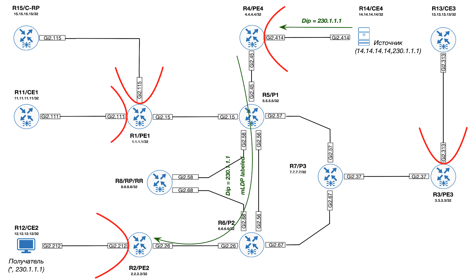
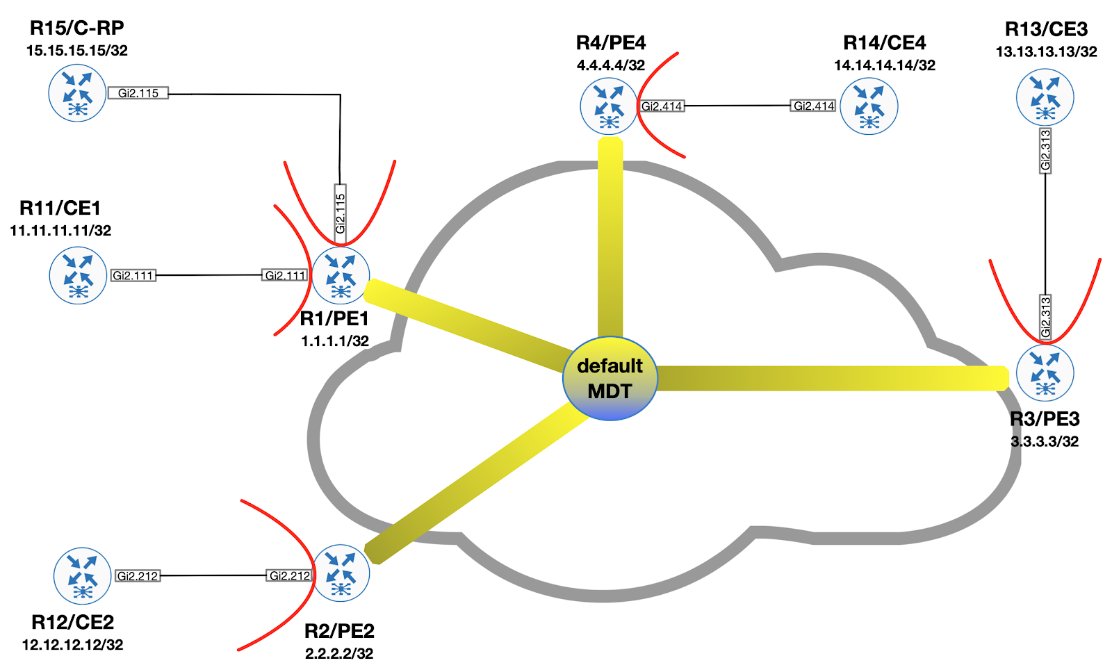
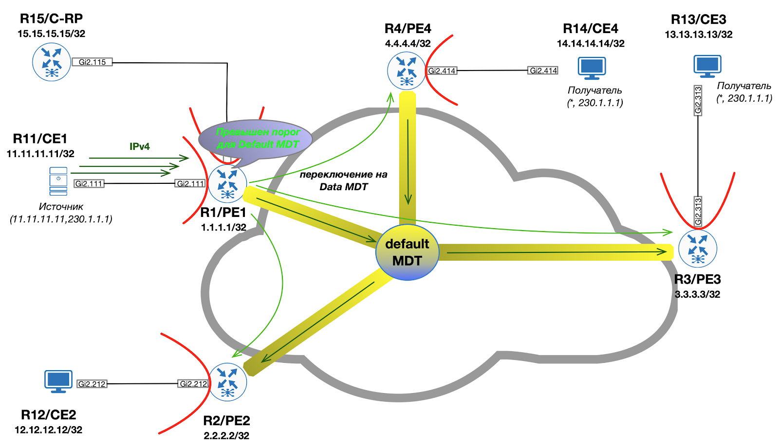
As we learned from past entries, in the backbone when implementing mVPN, there is always a Default MDT construct, to which all PE routers are connected. PIM service messages (eg Bootstrap, Auto-RP) as well as custom multicast traffic are carried within this MDT. As a result, it turns out that some PE devices receive even the traffic to which they did not subscribe.
If you want to know how to deal with this - welcome under the cat!
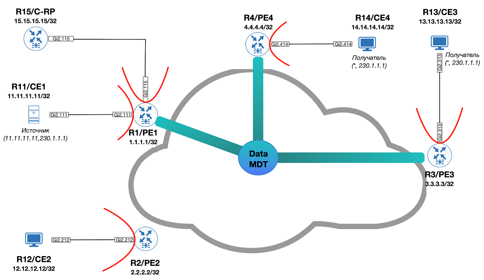
In order to improve the efficiency of data transmission, an additional construction is used, which is referred to as "Data MDT". The idea behind it is as follows:
- Within the tree, only C- (S, G) traffic is distributed
- Only those Egress PEs that have interested recipients become members of the tree
- The root Data MDT device is the Ingress PE (the router behind which the source is located)
Visually, it looks like this:
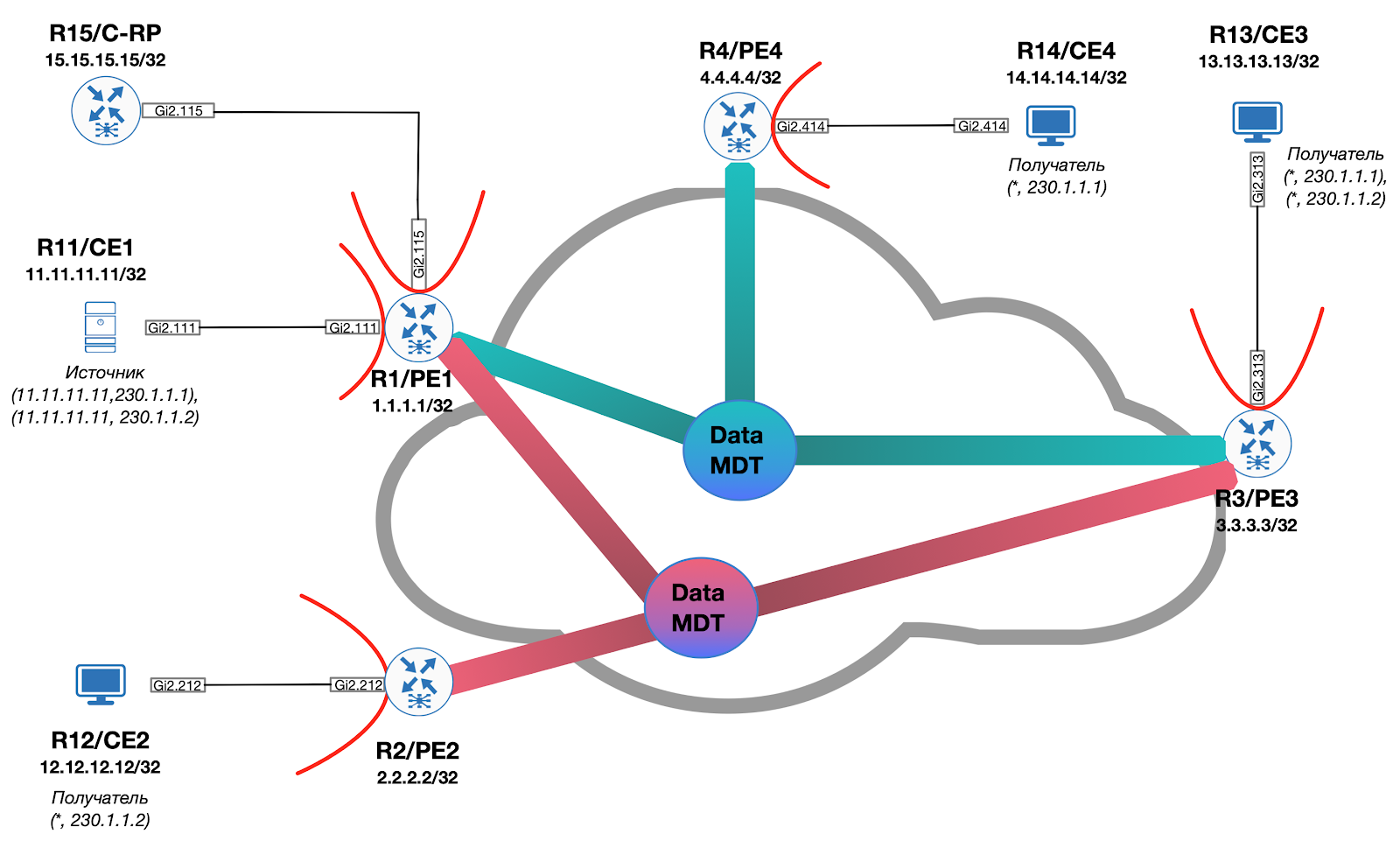
If we imagine a situation in which the source starts broadcasting to the second multicast group (230.1.1.2), for which the recipients are located only behind PE2 and PE3, then an additional Data MDT is created and the overall picture takes the form (Default MDT is omitted):
Signaling for traffic switching from Default MDT to Data MDT is carried out exclusively on demand when a predetermined threshold is exceeded by the Ingress PE either by means of PIM or by means of BGP.
Data MDT using PIM
If PIM is used for signaling, the ingress PE generates a special PIM Data-MDT TLV message and sends it as part of the Default MDT to ensure that all PEs can receive the message. Simultaneously with sending the Data MDT TLV, Ingress PE starts a timer equal to three seconds. After the timer expires, all packets will be transmitted within Data MDT.
It should also be noted that the information contained in the Data-MDT TLV is cached on all PEs. The reason for this is quite trivial - even if there are no interested traffic recipients on a particular PE at the moment, they may appear there after a while. Accordingly, upon receiving a PIM Join (within the C-VRF), the PE can instantly connect to the Data MDT already existing on the network.
Approx. Data-MDT TLVs are transmitted once per minute.
Each Data MDT is set up for a separate (S, G) route within the VPN / VRF. The administrator must explicitly specify the maximum number of Data MDTs that can be generated on the device. If at some point the number of newly installed trees reaches the specified limit, then the following trees will reuse the already installed ones.
Approx. As of this writing, Cisco IOS does not support PIM signaling over Data MDT. All profiles with this alarm are available only on the IOS XR operating system.
Data MDT with BGP
When using BGP in an overlay network for Data MDT signaling, the basic principles remain the same (compared to PIM):
- ingress PE signals to all PEs that traffic for C- (S, G) will be transmitted within Data MDT
- egress PE, upon receipt of a BGP update, joins the specified tree
- the mVPN addressing family (sAFI 129) is used for signaling.
It turns out that the Ingress PE must form a special BGP Update message and send it to all PEs within the mVPN. For this, a route of the third type is used.
Profile 14
Let's consider the described transition using the example of our laboratory. In particular, the configuration known as "Profile 14" is applicable. This profile is characterized by the use of BGP mVPN AD to build P2MP MLDP LSPs.
On PE we will use the following configuration template:
ip vrf C-ONE mdt auto-discovery mldp mdt partitioned mldp p2mp mdt overlay use-bgp mdt strict-rpf interface ! router bgp 1 address-family ipv4 mvpn neighbor 8.8.8.8 activate neighbor 8.8.8.8 send-community extended exit-address-family
Approx. we
mdt strict-rpf
'll talk about the purpose of the interface command in the next issue.
Auto-Discovery
Let's see what happens on PE1:
On each PE, an Lspvif0 interface is created, on which C-PIM is activated.
*Dec 3 10:04:54.450: %LINEPROTO-5-UPDOWN: Line protocol on Interface Lspvif0, changed state to up
There are no neighbors at the moment:
PE1#show ip pim vrf C-ONE int Address Interface Ver/ Nbr Query DR DR Mode Count Intvl Prior 172.1.11.1 GigabitEthernet2.111 v2/S 1 30 1 172.1.11.11 172.1.15.1 GigabitEthernet2.115 v2/S 1 30 1 172.1.15.15 1.1.1.1 Lspvif0 v2/S 0 30 1 1.1.1.1
Let's see the BGP table:
PE1#show bgp ipv4 mvpn all BGP table version is 39, local router ID is 1.1.1.1 Status codes: s suppressed, d damped, h history, * valid, > best, i - internal, r RIB-failure, S Stale, m multipath, b backup-path, f RT-Filter, x best-external, a additional-path, c RIB-compressed, t secondary path, Origin codes: i - IGP, e - EGP, ? - incomplete RPKI validation codes: V valid, I invalid, N Not found Network Next Hop Metric LocPrf Weight Path Route Distinguisher: 1.1.1.1:1 (default for vrf C-ONE) *> [1][1.1.1.1:1][1.1.1.1]/12 0.0.0.0 32768 ? *>i [1][1.1.1.1:1][2.2.2.2]/12 2.2.2.2 0 100 0 ? *>i [1][1.1.1.1:1][3.3.3.3]/12 3.3.3.3 0 100 0 ? *>i [1][1.1.1.1:1][4.4.4.4]/12 4.4.4.4 0 100 0 ? Route Distinguisher: 2.2.2.2:1 *>i [1][2.2.2.2:1][2.2.2.2]/12 2.2.2.2 0 100 0 ? Route Distinguisher: 3.3.3.3:1 Network Next Hop Metric LocPrf Weight Path *>i [1][3.3.3.3:1][3.3.3.3]/12 3.3.3.3 0 100 0 ? Route Distinguisher: 4.4.4.4:1 *>i [1][4.4.4.4:1][4.4.4.4]/12 4.4.4.4 0 100 0 ? Route Distinguisher: 1.1.1.1:1 (default for vrf C-ONE) *> [3][1.1.1.1:1][*][*][1.1.1.1]/14 0.0.0.0 32768 ? *>i [3][1.1.1.1:1][*][*][2.2.2.2]/14 2.2.2.2 0 100 0 ? *>i [3][1.1.1.1:1][*][*][3.3.3.3]/14 3.3.3.3 0 100 0 ? *>i [3][1.1.1.1:1][*][*][4.4.4.4]/14 4.4.4.4 0 100 0 ? *> [3][1.1.1.1:1][*][224.0.0.13][1.1.1.1]/18 0.0.0.0 32768 ? Route Distinguisher: 2.2.2.2:1 *>i [3][2.2.2.2:1][*][*][2.2.2.2]/14 2.2.2.2 0 100 0 ? Route Distinguisher: 3.3.3.3:1 *>i [3][3.3.3.3:1][*][*][3.3.3.3]/14 3.3.3.3 0 100 0 ? Network Next Hop Metric LocPrf Weight Path Route Distinguisher: 4.4.4.4:1 *>i [3][4.4.4.4:1][*][*][4.4.4.4]/14 4.4.4.4 0 100 0 ?
As you can see, in addition to the routes of the first type already considered earlier, the routes of the third type S-PMSI AD are added, which are used to advertise PE as an Ingress router for a specific C- (S, G) group. At the moment, the group is (*, *). This indicates the desire of PE to participate in the construction of Partitioned MDT.
Obviously, for the data transfer to work, the rendezvous point information must be known within the VRF. In our case, CE15 acts as RP and BSR.
C-RP#sh run | i pim ip pim bsr-candidate Loopback0 0 ip pim rp-candidate Loopback0
Since the C-RP has built a PIM neighborhood with PE1, the information about RP is also known on this PE1:
PE1#show ip pim vrf C-ONE rp mapping Auto-RP is not enabled PIM Group-to-RP Mappings Group(s) 224.0.0.0/4 RP 15.15.15.15 (?), v2 Info source: 15.15.15.15 (?), via bootstrap, priority 0, holdtime 150 Uptime: 01:25:50, expires: 00:01:26
It is necessary to deliver this information to all other PE / CEs. How to do it? To better understand the principle, I propose to go from the opposite and start looking at the already known information on CE2:
CE2#show ip pim rp mapping Auto-RP is not enabled PIM Group-to-RP Mappings Group(s) 224.0.0.0/4 RP 15.15.15.15 (?), v2 Info source: 15.15.15.15 (?), via bootstrap, priority 0, holdtime 150 Uptime: 01:27:54, expires: 00:02:26
As you can see, the PIM BSR messages have spread over the mVPN infrastructure. Let's see the traffic dump on PE1:
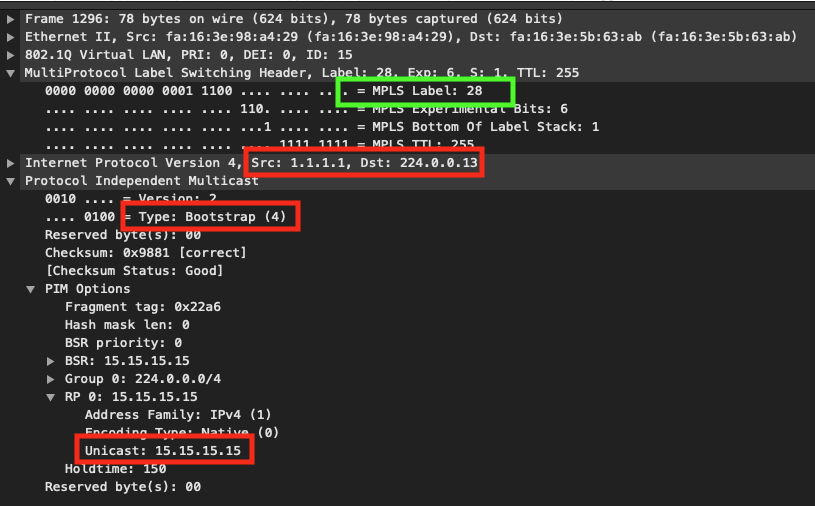
As you can see, PE1 encapsulates the PIM BSR message inside MPLS and marks it with 28. Where does it come from? We can assume that since this packet reached CE2 (and hence PE2), that is, some LSP before PE2.
PE2#show mpls mldp database * For interface indicates MLDP recursive forwarding is enabled * For RPF-ID indicates wildcard value > Indicates it is a Primary MLDP MDT Branch LSM ID : 1 Type: P2MP Uptime : 04:17:40 FEC Root : 2.2.2.2 (we are the root) Opaque decoded : [gid 65536 (0x00010000)] Opaque length : 4 bytes Opaque value : 01 0004 00010000 Upstream client(s) : None Expires : N/A Path Set ID : 1 Replication client(s): > MDT (VRF C-ONE) Uptime : 04:17:40 Path Set ID : None Interface : Lspvif0 RPF-ID : * LSM ID : 3 Type: P2MP Uptime : 01:30:06 FEC Root : 1.1.1.1 Opaque decoded : [gid 131071 (0x0001FFFF)] Opaque length : 4 bytes Opaque value : 01 0004 0001FFFF Upstream client(s) : 6.6.6.6:0 [Active] Expires : Never Path Set ID : 3 Out Label (U) : None Interface : GigabitEthernet2.26* Local Label (D): 34 Next Hop : 10.2.6.6 Replication client(s): MDT (VRF C-ONE) Uptime : 01:30:06 Path Set ID : None Interface : Lspvif0 RPF-ID : *
From the analysis of the mLDP database, it can be seen that on PE2 there is a certain tree (LSM ID: 3), the root of which is PE1 (IP = 1.1.1.1), Opaque = 01 0004 0001FFFF and for this tree a local label 34 was generated, which was sent to the neighbor R6 ( P2).
How did PE2 know about the tree, the root of which is PE1, and even got an Opaque for it? The answer is simple - using BGP route type 3.
When PE1 received the PIM BSR, it generated an additional BGP route that describes the group (*, 224.0.0.13) (remember that this is a reserved address for sending all PIM service messages). This route serves to advertise a new mLDP multicast tree. Inside the PTA is the Opaque value to be used for signaling via mLDP.
PE1#show bgp ipv4 mvpn all route-type 3 * 224.0.0.13 1.1.1.1 BGP routing table entry for [3][1.1.1.1:1][*][224.0.0.13][1.1.1.1]/18, version 116 Paths: (1 available, best #1, table MVPNv4-BGP-Table, not advertised to EBGP peer) Advertised to update-groups: 1 Refresh Epoch 1 Local 0.0.0.0 from 0.0.0.0 (1.1.1.1) Origin incomplete, localpref 100, weight 32768, valid, sourced, local, best Community: no-export Extended Community: RT:65001:1 PMSI Attribute: Flags: 0x0, Tunnel type: 2, length 17, label: exp-null, tunnel parameters: 0600 0104 0101 0101 0007 0100 0400 01FF FF rx pathid: 0, tx pathid: 0x0
Thus, by importing this route, PE2 can initiate mLDP signaling towards PE1 for the tree (*, 224.0.0.13). For the label received from PE2, P2 (R6) generates its own local one (29) and sends it towards P1 (R5):
P2#show mpls mldp database * For interface indicates MLDP recursive forwarding is enabled * For RPF-ID indicates wildcard value > Indicates it is a Primary MLDP MDT Branch LSM ID : 2 Type: P2MP Uptime : 01:40:24 FEC Root : 1.1.1.1 Opaque decoded : [gid 131071 (0x0001FFFF)] Opaque length : 4 bytes Opaque value : 01 0004 0001FFFF Upstream client(s) : 5.5.5.5:0 [Active] Expires : Never Path Set ID : 2 Out Label (U) : None Interface : GigabitEthernet2.56* Local Label (D): 29 Next Hop : 10.5.6.5 Replication client(s): 2.2.2.2:0 Uptime : 01:40:24 Path Set ID : None Out label (D) : 34 Interface : GigabitEthernet2.26* Local label (U): None Next Hop : 10.2.6.2
P1 (R5) does the same, generating its local label for the tree and sending it to PE1:
P1#show mpls mldp database * For interface indicates MLDP recursive forwarding is enabled * For RPF-ID indicates wildcard value > Indicates it is a Primary MLDP MDT Branch LSM ID : 2 Type: P2MP Uptime : 01:41:24 FEC Root : 1.1.1.1 Opaque decoded : [gid 131071 (0x0001FFFF)] Opaque length : 4 bytes Opaque value : 01 0004 0001FFFF Upstream client(s) : 1.1.1.1:0 [Active] Expires : Never Path Set ID : 2 Out Label (U) : None Interface : GigabitEthernet2.15* Local Label (D): 28 Next Hop : 10.1.5.1 Replication client(s): 4.4.4.4:0 Uptime : 01:41:24 Path Set ID : None Out label (D) : 34 Interface : GigabitEthernet2.45* Local label (U): None Next Hop : 10.4.5.4 7.7.7.7:0 Uptime : 01:41:24 Path Set ID : None Out label (D) : 30 Interface : GigabitEthernet2.57* Local label (U): None Next Hop : 10.5.7.7 6.6.6.6:0 Uptime : 01:41:24 Path Set ID : None Out label (D) : 29 Interface : GigabitEthernet2.56* Local label (U): None Next Hop : 10.5.6.6
Visually, the whole process is shown in the figure below:
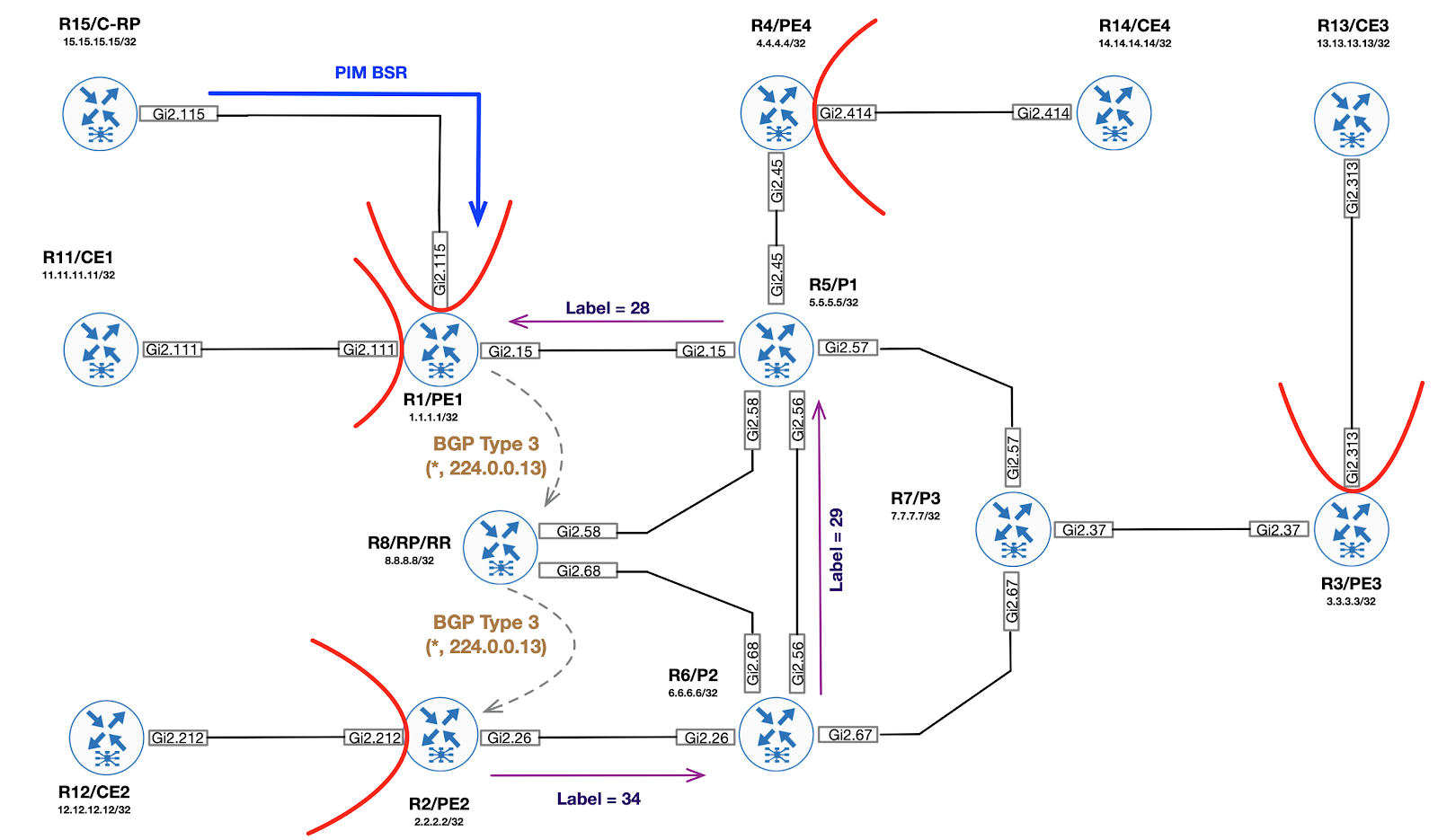
Joining a Shared Tree and building a root P2MP tree (ROOT = RP-PE)
Step 2. A traffic receiver appears on the network. After Egress PE (PE2) receives a PIM Join from CE for C - (*, G), PE2 performs RPF check to find BGP Next-Hop towards C-RP. Found Next-Hop (1.1.1.1) will be used as Partitioned MDT ROOT for mLDP.
Additionally, PE2 creates an Lspvif interface inside the C-VRF:
PE2# *Dec 3 14:46:21.606: %LINEPROTO-5-UPDOWN: Line protocol on Interface Lspvif1, changed state to up PE2# *Dec 3 14:46:22.310: %PIM-5-DRCHG: VRF C-ONE: DR change from neighbor 0.0.0.0 to 2.2.2.2 on interface Lspvif1
Step 3. Egress PE (PE2) generates mLDP mapping message towards RP-PE (ROOT P2MP MDT) using Opaque value from BGP update.
PE2#show mpls mldp database summary LSM ID Type Root Decoded Opaque Value Client Cnt. 4 P2MP 1.1.1.1 [gid 65536 (0x00010000)] 1 1 P2MP 2.2.2.2 [gid 65536 (0x00010000)] 1 3 P2MP 1.1.1.1 [gid 131071 (0x0001FFFF)] 1 PE2# PE2#show mvpn ipv4 vrf C-ONE auto-discovery s-pmsi * * detail I-PMSI - Intra-AS Inclusive-PMSI, S-PMSI - Selective-PMSI * - Indicates Wildcard source or group address [S-PMSI][1.1.1.1:1][*][*][1.1.1.1], Joined Orig: Remote Uptime: 04:44:27 Type: MLDP P2MP Root: 1.1.1.1 Fec-Opq: 1 Global-Id: 65536 (0x10000) [S-PMSI][3.3.3.3:1][*][*][3.3.3.3], Orig: Remote Uptime: 04:44:22 Type: MLDP P2MP Root: 3.3.3.3 Fec-Opq: 1 Global-Id: 65536 (0x10000) [S-PMSI][4.4.4.4:1][*][*][4.4.4.4], Orig: Remote Uptime: 04:44:20 Type: MLDP P2MP Root: 4.4.4.4 Fec-Opq: 1 Global-Id: 65536 (0x10000) [S-PMSI][2.2.2.2:1][*][*][2.2.2.2], Joined Orig: Local Uptime: 04:44:24 Type: MLDP P2MP Root: 2.2.2.2 Fec-Opq: 1 Global-Id: 65536 (0x10000) PE2#show mpls mldp database opaque_type gid 65536 LSM ID : 4 Type: P2MP Uptime : 00:03:43 FEC Root : 1.1.1.1 Opaque decoded : [gid 65536 (0x00010000)] Opaque length : 4 bytes Opaque value : 01 0004 00010000 Upstream client(s) : 6.6.6.6:0 [Active] Expires : Never Path Set ID : 4 Out Label (U) : None Interface : GigabitEthernet2.26* Local Label (D): 35 Next Hop : 10.2.6.6 Replication client(s): MDT (VRF C-ONE) Uptime : 00:03:43 Path Set ID : None Interface : Lspvif1 RPF-ID : 0x1
Step 4. Egress PE generates BGP route of the sixth type (joining the Shared Tree towards RP-PE). This route is only imported to RP-PE.
PE2#show bgp ipv4 mvpn all route-type 6 1.1.1.1:1 65001 15.15.15.15 230.1.1.1 BGP routing table entry for [6][1.1.1.1:1][65001][15.15.15.15/32][230.1.1.1/32]/22, version 130 Paths: (1 available, best #1, table MVPNv4-BGP-Table) Advertised to update-groups: 1 Refresh Epoch 1 Local 0.0.0.0 from 0.0.0.0 (2.2.2.2) Origin incomplete, localpref 100, weight 32768, valid, sourced, local, best Extended Community: RT:1.1.1.1:1 rx pathid: 1, tx pathid: 0x0
Step 5. RP-PE translates the received BGP route of the sixth type in the PIM Join towards RP. At this point, the RP is ready to send multicast traffic towards the Egress PE. You need to deliver traffic from source to RP.
PE1#show ip mroute vrf C-ONE | b \( (*, 230.1.1.1), 00:07:08/stopped, RP 15.15.15.15, flags: SG Incoming interface: GigabitEthernet2.115, RPF nbr 172.1.15.15 Outgoing interface list: Lspvif0, Forward/Sparse, 00:07:08/stopped
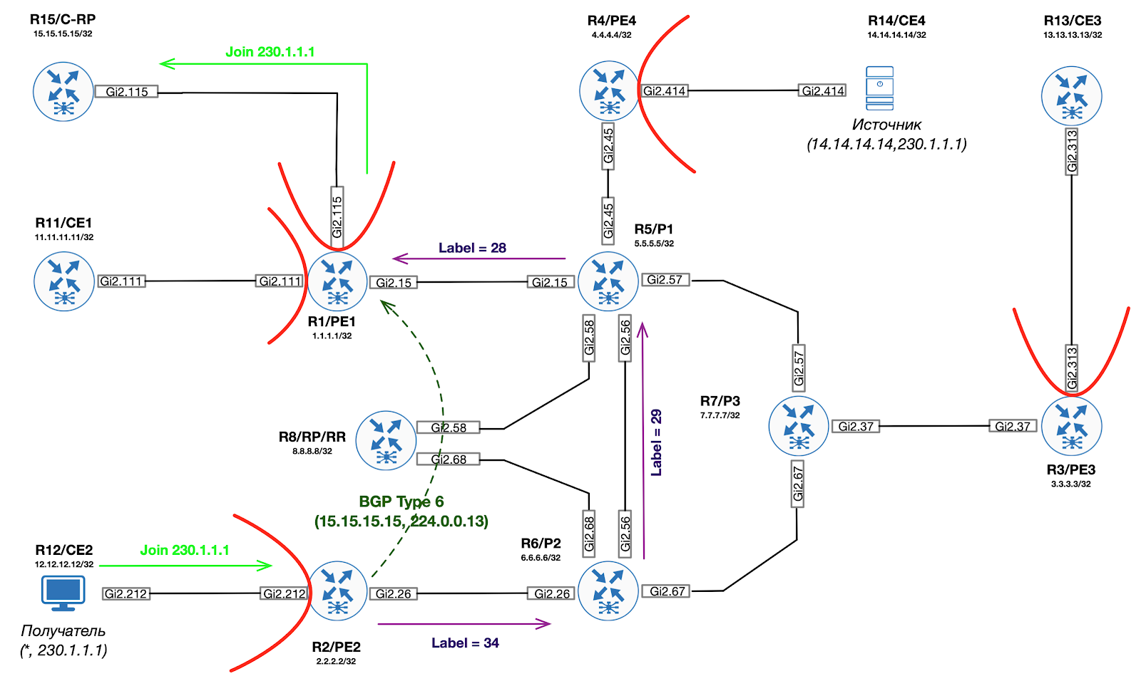
Step 6. When S-PE (PE4) receives the first multicast packet from source (CE4), the traffic is encapsulated inside the PIM Register message and sent as a unicast packet towards the C-RP (using normal MPLS L3 VPN rules).
Step 7. After receiving the PIM Register, the C-RP begins the process of building the C- tree (14.14.14.14, 230.1.1.1). RP-PE receives PIM Join for C- (14.14.14.14, 230.1.1.1) from C-RP. This message is translated into BGP route type 7. However, before sending to the source side, you need to build a new Partitioned MDT tree with PE as the ROOT.
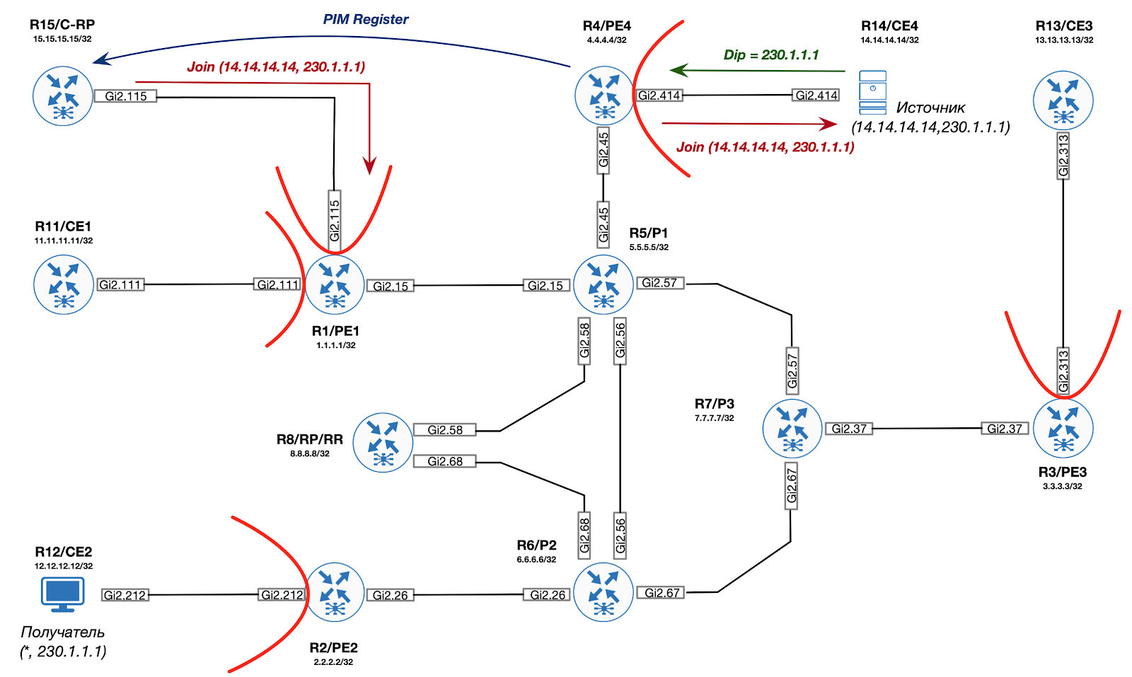
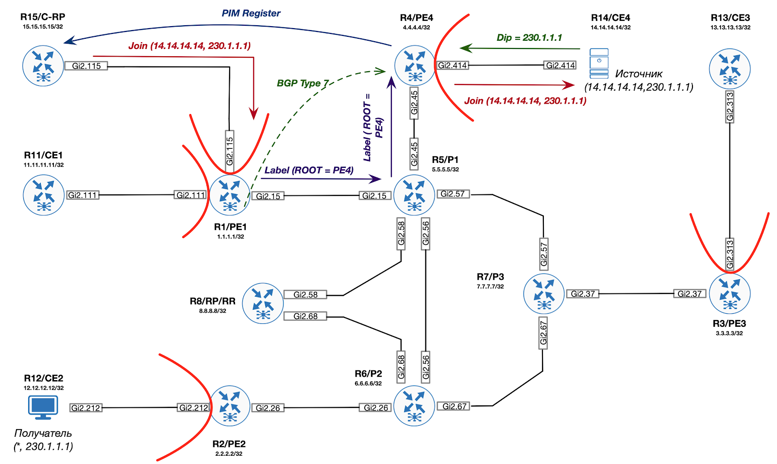
Step 8. RP-PE performs RPF checks to find BGP Next-Hop towards the source. This address will be used as Partitioned MDT ROOT for mLDP.
Step 9. Using the received BGP Next-Hop and BGP route of the third type from Ingress PE, RP-PR generates a mLDP mapping message towards the Ingress PE IP address, thereby building the root P2MP tree to Ingress PE.
Step 10. RP-PE sends BGP route type 7 (Join from RP) towards Ingress PE.
Step 11. Ingress PE converts the received BGP route of the seventh type into PIM Join and sends it towards the traffic source.
Attach to Source Tree and build P2MP (ROOT = S-PE)
Step 12. The Ingress PE also sends a Type 5 BGP route to all mVPN PEs, thereby informing them that there is an active source in the network. This route is a trigger to switch to the SPT tree.
Step 13. Egress PE uses the received BGP route type 5 to generate mLDP mapping message towards Ingress PE (MDT information is taken from BGP route type 3).
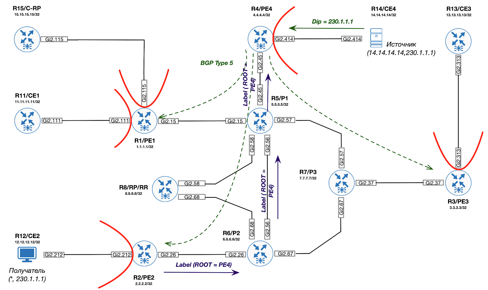
Thus, traffic can now be redirected in an optimal way from source to destination using mpls (mLDP) tags.