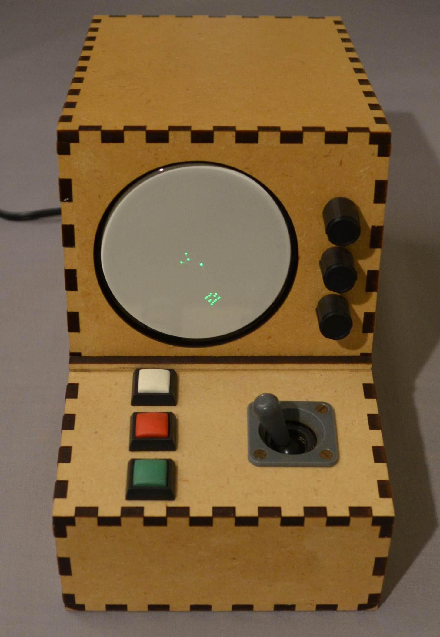
As an engineer, I have always been impressed by the pragmatic Russian style of naming new products. While some Western marketer might call a small CRT-based gaming device The Vectormatic Score-Master 3000, Russians tend to use more meaningful names. And since they are considering a third attempt at creating a vector rendering system, they would call it "Vector Drawing Machine # 3". Engineers - marketers score (15: 0).
Many years ago, I was fascinated by the idea of using a small oscilloscope cathode ray tube to display an analog clock. This undertaking, of course, promised aesthetic pleasure, but at the same time it seemed ridiculous. The idea of replacing the chain of mechanical connections with a microcontroller that drives two high-voltage differential amplifiers and an independent high-voltage power supply just to, roughly speaking, tell the time seemed a little silly.
If, at the same time, we take into account all the work on the implementation of each stage of the process, as a result of which a decent-looking device should be obtained, and add a detailed study of the design, then the whole project already hinted at its monumentality.
None of the many proposed tasks presented any particular difficulties in itself, but if we take it as a whole, it is the stage of integrating everything together in such projects that reveals the complexities of the interrelationships of individual components.
This article discusses the assembly of a simple space game based on a CRT. This project describes the architecture, provides design notes, comments on the equipment used, the electronics, the implementation of the high voltage power supply, and the process of laser cutting the enclosure.
General information
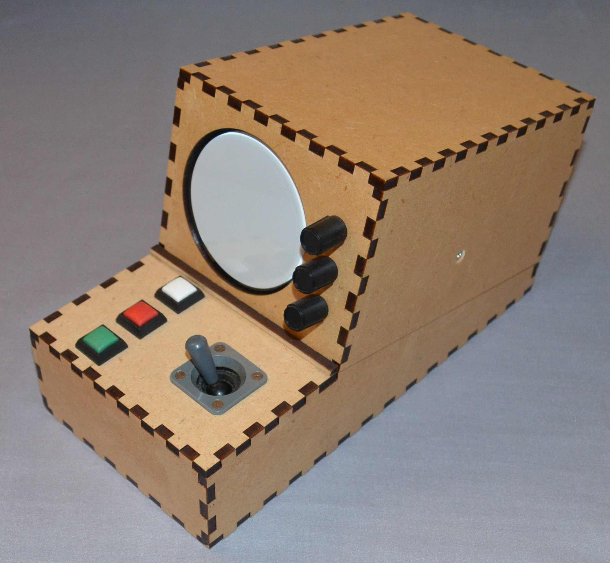
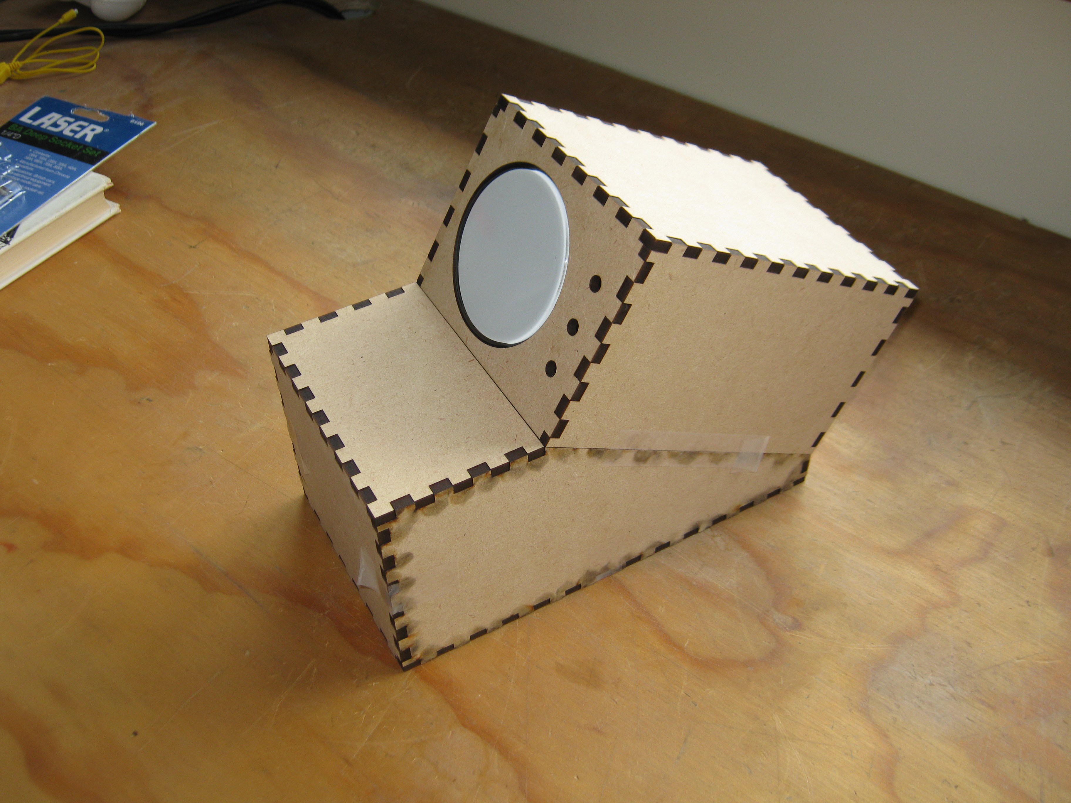
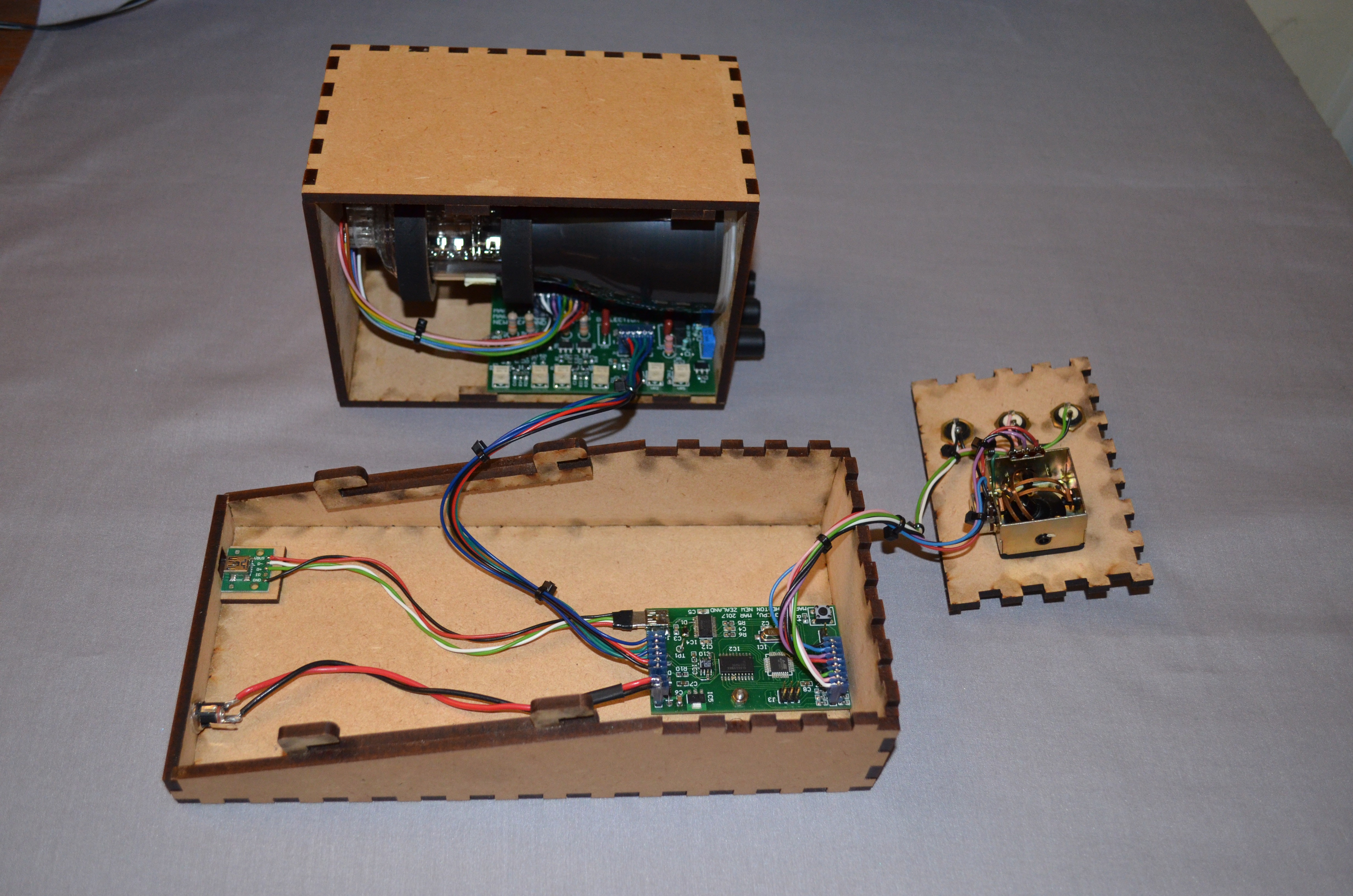
The body is assembled from two main parts, made of MDF board using laser cutting. The upper part houses a CRT display, a high voltage power supply, deflection channels and corresponding calibrators. At the bottom there is a joystick, buttons, a microcontroller and a low voltage power supply. At the back there is a power connector and a USB mini B socket. The upper segment of the case is put on the lower one, and the whole structure is fixed by a flat control panel, on which there is a joystick and buttons.
CRT
The CRT used is the D7-16G, which is just over 76mm in diameter, 160mm in length and runs on battery power. I bought three of these CRTs many years ago just for similar projects.
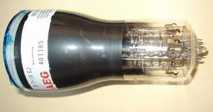
CRT D7-16G
It uses an 11-pin connector type 30-232, which is very problematic to find. After some deliberation, I got the idea to assemble my own by cutting a blank with a laser from a sheet of acrylic and picking up the appropriate contact pins from the lamp panel base.
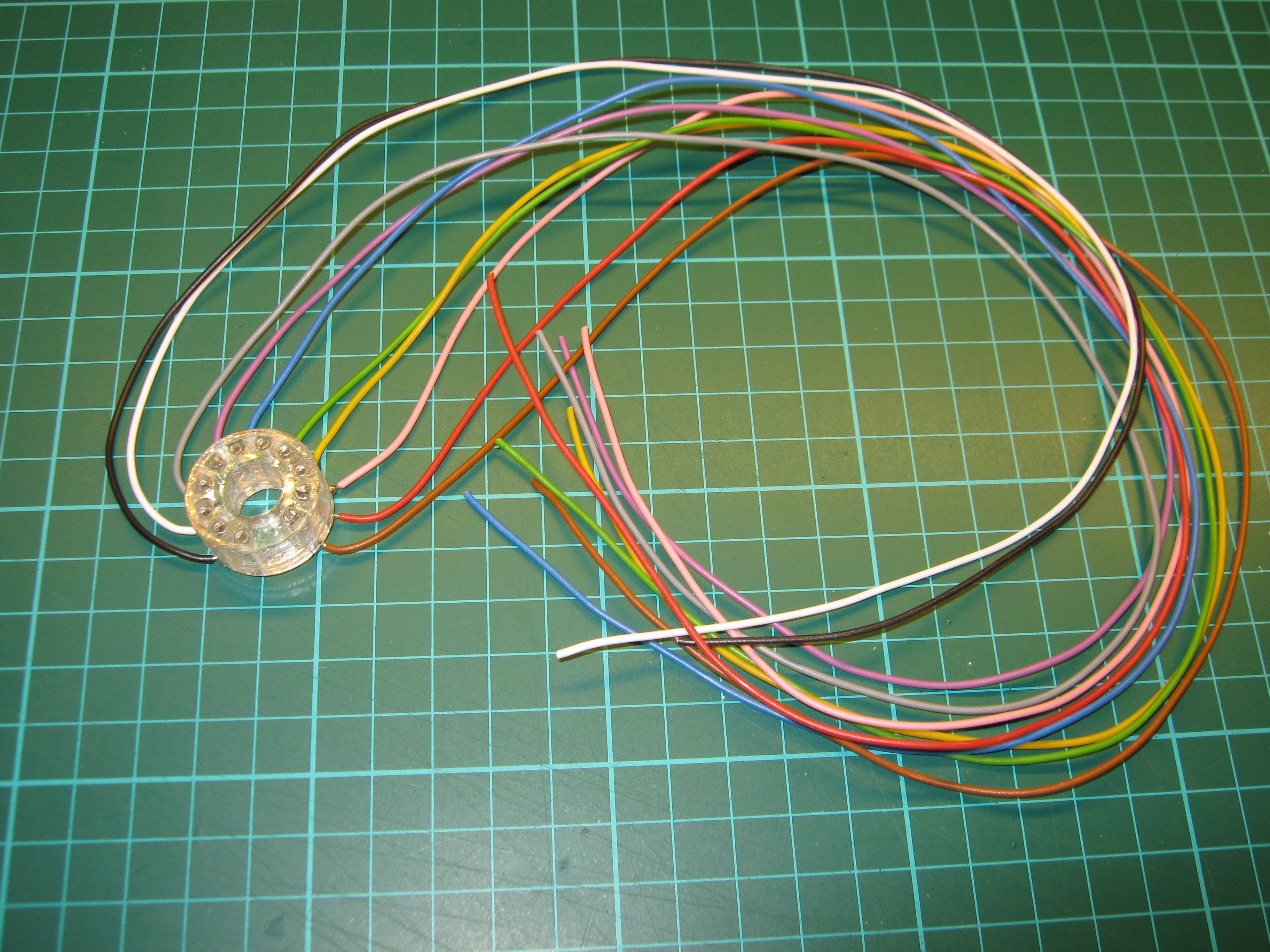
Assembly Connector 30-232
To do this, I designed two composite blanks at Autocketch so that the CRT contacts are positioned along the “D” contour of the left part. Then each piece was cut from 3mm acrylic sheet and glued together. I removed the contacts from the new B9A lamp panel, inserted them into the glued blank and slightly bent to fix them, then soldered wires to their terminals, insulating the connections with heat shrinkage.
High voltage power supply
This unit is based on the SG3525 switching regulator driving an N-FET push-pull stage followed by a small ferrite transformer with high and low voltage secondary coils. The high-voltage side is passed through a positive half-wave rectifier, generating about 240VDC, and then reduced by a parallel regulator to 210V. The rectified voltage is fed to the deflection amplifiers and consumes about 7mA. The HV secondary voltage is also doubled, generating approximately -600V, 1mA to bias the electron gun beam. Balancing any DC secondary winding capable of saturating the core or causing magnetic displacement is accomplished by positive and negative rectifiers.
The structure of the transformer starts with a primary winding in the middle, after which there is a grounded start of the HV secondary winding, ending with a terminal under anode voltage. Finally, there is a low voltage winding that is used to heat the cathode ray tube coil. This order is chosen to avoid breakdown between the high and low voltage windings. Having said all this, I thought about this topology and, perhaps, will find time to refine it.
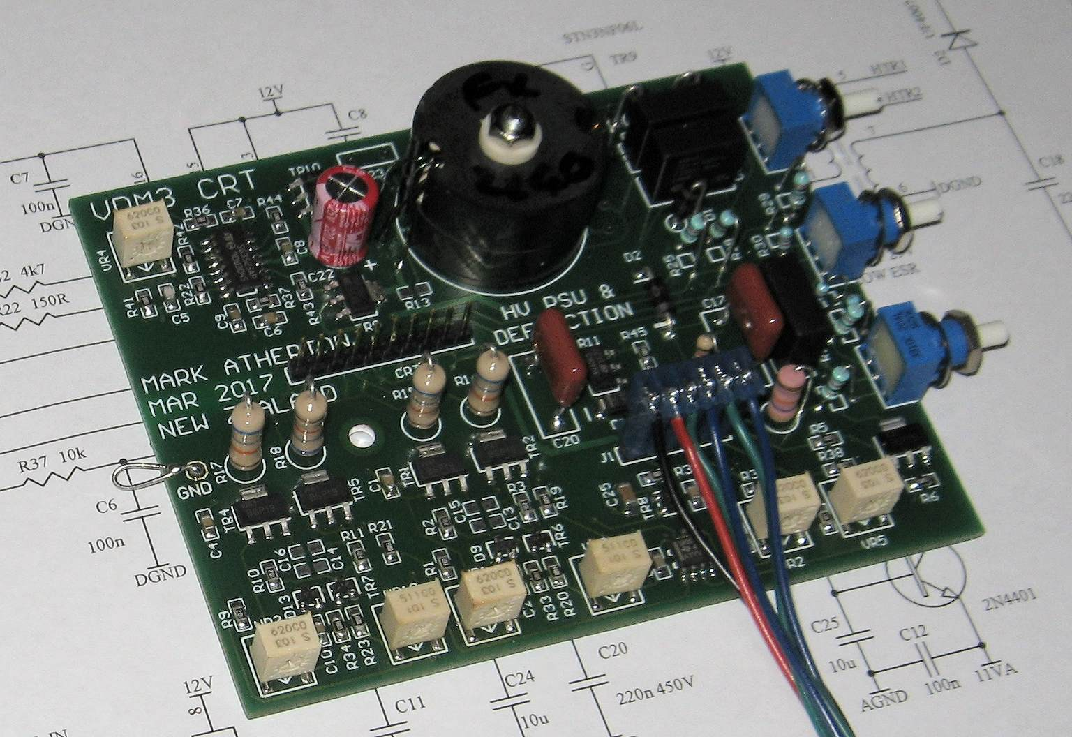
HV unit and deflection device
I have not used a ferrite armor core for so long that I completely forgot about its electrical conductivity. This created electronic arcs between the top of the secondary and the grounded ferrite, causing several pairs of STN3NF06L primary side transistor drivers to fail. In the course of finding out the reason, I replaced them with a pair of more stable TO252 (100A / 8mΩ), capable of withstanding even the supply of 12V, 1A and starting a transformer with short-circuited turns.
I was somewhat confused to find that the SG3525 is available in both wide and narrow SOIC packages. As a result, the PCB footprint was found to be unsuitable and the narrow part had to be ordered from the UK.
Deflection amplifier
The design of this subsystem proved to be a daunting task, and it took a lot of time to work with the SPICE simulator, which helped to understand all the nuances.
Here's a quick spec:
- unbalanced input 0..5V
- differential output with a swing> 80V per arm
- at 210V current consumption less than 2mA
- possibility of power supply from 12V
- no negative tires
- bandwidth> 500 kHz with less than 5 ° phase shift in relation to the calculated
Over the course of several days, I learned several topologies, starting with a cascode push-pull circuit with a current source. Initially, only the stationary mode was tested and optimized. After reaching the baseline DC values, I took up the AC parameters. The capacitor connecting the emitters of the push-pull circuit (not surprisingly) significantly affects the AC gain, frequency, phase characteristics and, apparently, strongly interacts with the emitter resistors, as well as the drains associated with them.
Here, as an improvement, thermal stabilization can be applied by thermal bonding of the output devices (if we consider that it is now SOT-233, then the task is not easy). Alternatively, of course, you can switch to their counterparts that are mounted in holes, which will greatly simplify the task.
It would be nice to use a circuit in which the phase shift and gain are less dependent. But the current simple option, so, has overcome many difficult technical barriers, so the additional requirement would be too burdensome.
Controller board and DAC
Considering that the main task of the microcontroller is the repeated calculation of a row of vector pairs every few tens of milliseconds, it seemed to me reasonable to use an inexpensive and simple option for this.
The ATmega328P and ST micro STM32F103C8T6 were obvious candidates. As a result, the first was chosen solely for its wider opportunities and (once) popularity. In the process of assembling the board, it was surprisingly found out that I accidentally bought a version “B” controller, but more on that later.
Overall, its board is simple and includes an FT232RL USB converter, a dual channel 8-bit DAC, a joystick and button interface, an optional I2C interface, and a 5V regulator. It was possible to use the Arduino Nano with a motherboard, but the current solution was simple and easy to connect.
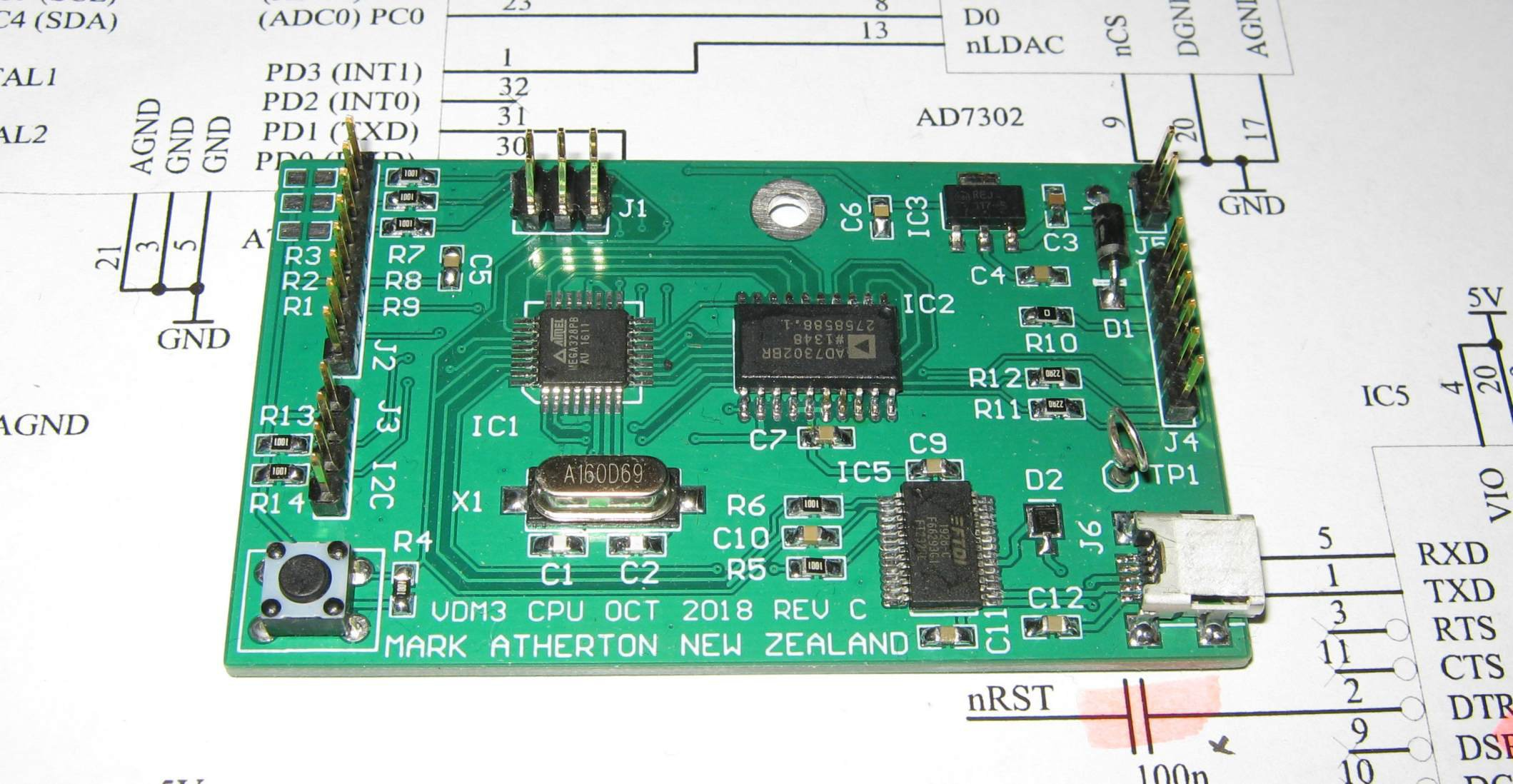
Controller board and DAC
System requirements imply operation with one bus, which limits the choice of DAC. Initially, I took the TLC7528, which seems to have a current output, but on closer examination it turned out that it can be configured to work in the voltage output mode. Combined with the TSH82 operational amplifiers, this turned out to be a poor choice, as distortion even at the lowest signal levels was a few percent. I solved this problem by replacing the DAC with the AD7302, which has two voltage outputs and a settling time of 2μs.
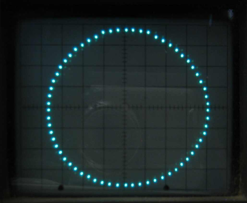
A few percent distortion can mess things up
With hindsight, it seems that the distortion with the TLC7528 may have been due to the limited input common-mode range of the associated TSH82. This can be easily verified by removing these op amps and drawing a Lissajous circle on the oscilloscope directly with the probes.
As a result, a number of design errors prompted me to rebuild this seemingly simple board: choosing a DAC, using the FT232RL for the first time, and not tying the corresponding TST pin to ground. I also made a mistake in the circuit for connecting the USB connector on the board (I mixed up the signal wires), which I temporarily corrected using a homemade cable.
New microcontroller, toolkit and bootloader
As I said, surprisingly it turned out that the ATmega328Ps I had ordered earlier were inexplicably the less popular “B” variant. They are fully binary compatible with their younger siblings, except for the chip signature. However, the newer version has a number of useful additional functions, including support for a second USART.
Arduino provides the latest toolkit which, oddly enough, was not available on the Atmel site. These tools had to be removed and assembled in a portable package, and therefore no longer relied on the Arduino framework. Then I updated the corresponding project makefile to reference the new controller and tools.
Given the compatibility of the chips, the standard Arduino bootloader was programmed on a newer one using a relatively small AVR Studio 4 IDE, which I chose for its simplicity of interface. The XML description file for the new controller had to be created based on the old version. As a result, the main differences were its number and the corresponding signature.
The make utility was used to flash the project and, accordingly, the makefile. With this approach, the toolkit took only about 30MB, and not hundreds, as is the case with the use of "modern" integrated IDEs.
Real programmers don't use IDEs
Firmware
The system is designed to draw about 10K vector pairs per second. With a refresh rate of 50Hz, this means that 200 vectors can be drawn. After every 200 vectors (20ms), the foreground receives a signal to update their list so that the game can run smoothly enough.
Several system processes require the ability to rotate vectors. At the same time, despite the obvious reasonableness of using a decimal value in the range of 0..359 degrees, such a solution will require using U16 and will be unnecessarily cumbersome. After some thought, I decided that it would be appropriate to process as much data as possible with the S8 (+127 to –128). It will also work well for representing X / Y coordinates (assuming an 8-bit DAC) to express an angle (approximately ± 180 degrees).
Screen refresh is done through a timer interrupt and is the only way to control the DACs. Vectors are read from the ping or pong buffer and repeated until the foreground task switches the buffer. Each buffer starts at counter U8 and continues to the next available write point followed by a read point. After that it contains a list of X and Y values stored in U8 format.
The direction of the spacecraft is changed by moving the joystick left / right. The ship itself is displayed in the form of four points a la chevron from the TV series Star Trek, revolving around its center. Each vector requires a sin and cos search, 4 multiplications, and two additions. In total, 37 calculations per rotation are obtained, which in total is about 200 instructions. The spaceship will always be drawn first, and the nose will always be the first vector pair, so in the output buffer this vector pair will be the starting point for launching rockets.
Missiles are launched by pressing the corresponding button. They fly out of the bow of the ship and continue on its current course. The destruction of a rocket, of which no more than 16 can be launched simultaneously, occurs when it collides with an asteroid or when it reaches the visible radius of space. This flight model is based on drawing lines between the bow of the ship and the edge of the visible radius, where delta X and delta Y are calculated at launch. Delta X / Y is a fixed point of 8.8, as is speed.
Ship in center, asteroid below Asteroid
objects spawn in a random spot of radius and fly over it directly at an angle between 80 and 140 degrees. When they appear, a random start and end position is generated, which are then converted into Cartesian coordinates, and the question of a straight line is solved in much the same way as with the missiles.
When a rocket hits an asteroid, both entities are destroyed, and the current score counter is increased. The numerical display objects are taken from the "7-segment" lookup table.
All the "heavy" gameplay is done with the "spin" function, which is used to add an input object (asteroid, spaceship, 7-segment value, etc.) to the output buffer. In addition, it allows the input object to rotate, as well as apply an offset along the X and Y axes. At the same time, there is nothing stopping you from adding a 2x2 platoon of alien ships to the input buffer, then take them as a group and deploy them before drawing.
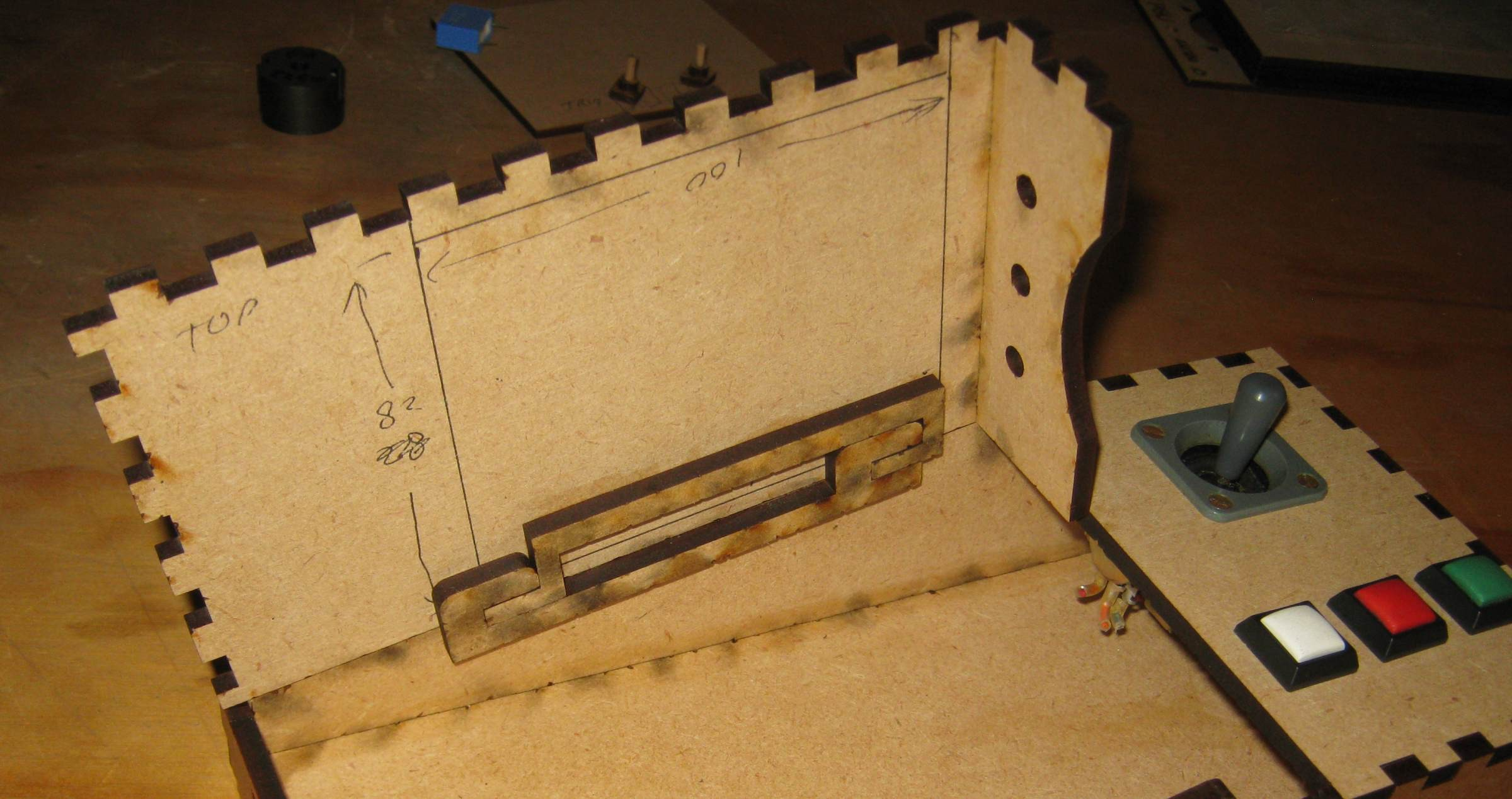
Mechanical part
Giving this space device aesthetics already required much more effort, although the process itself was much more entertaining than I expected. Initially, the slope of the CRT body was noticeably lower than planned, and in the end it took several hours to find a way to cut the sliding retention segment so that the upper and lower parts could be connected in a suitable way.
Primary Design
What a big difference literally a few degrees can make. I was amazed at how much of the aesthetic change in the end, and how crooked the first version looked with the most angled.
Kit: CRT module, bottom segment of the case and front panel cover of the
CRT are fixed with round MDF brackets glued to the top of the compartment. From the inside, these brackets are sheathed with elastic foam rubber on an adhesive basis.
Empty CRT front with a housing lock and markings for a printed circuit board
It is difficult to see from the photographs that the control panel with a joystick and buttons securely fixes the CRT module, preventing it from being pulled out backwards.
Packages used for hull design
For the initial design of the upper and lower body segments, the Inkscape editor with the extension “The Laser Cut Box” was used. Only serrated notches served as a bundle of these segments. I just copied and pasted the final template from Inkscape into Autosketch, in which I made all the necessary improvements.
I used a 70W laser cutter to cut MDF blanks. The working cycle turned out to be fast enough, which made it possible to simultaneously try out alternative design ideas.
Conclusion
As I expected, on this project I managed to learn a lot, since everything, except perhaps the built-in microcontroller, turned out to be beyond my ordinary experience.
Obviously, many different games and applications can be developed based on this vector rendering device. So far, I definitely want to add a synchronization module to the board (via I2C), having realized my long-standing idea of displaying an analog clock. The rest of the possible improvements will be made gradually.
An indecent mistake, of course, was a mistake with the USB mini B circuit and the first unsuccessful attempt to use a DAC with a current output in the voltage output mode. But otherwise I don't even know what else I would fix in case of reassembling such a unit.
In the current project, all the goals were achieved, including broadening the horizons, during which, as often happens, there were some surprises.
Contact the author Mark Atherton by mail markaren1@xtra.co.nz

