
Everything works as follows: there is a player with two buttons. One allows you to turn on music or pause playback, and the second allows you to shuffle songs. In addition, you can select an RFID card and bring it to the reader, which allows you to include a specific composition. This, in its essence, reproduces the process of listening to music in ancient times, when in order to turn on the desired recording, it was necessary to insert an ordinary CD or an ordinary cassette into the player. But here the old approach is supplemented with new technologies, which makes it easier for people with certain limitations to listen to music.
Although my grandmother is no longer with us, I still wanted to do this project. While my parents were cleaning up the house, I came across my mother's old cassette recorder. “Eureka!” - I thought. As a result, this tape recorder formed the basis for my version of the Juuke. I basically did everything the same way as Ananords, and it worked as it should, but I also extended the project with some ideas of my own. Namely, we are talking about the following:
- The ability to play an entire album using one RFID card.
- Ability to skip recording and move to the next recording.
- The ability to play music "recorded" on different "sides" of the card (A and B), which resembles the playback of conventional cassettes.
- Using the same number of buttons, but using short and long presses on them.
And now - to the point.
Materials and tools
When choosing materials for my project, I deviated a little from the set of components that was used in Juuke. This is what my turntable is made of:
- Arduino Nano board (instead of the Arduino Uno board used in Juuke).
- DFPlayer Mini audio file player module.
- MicroSD card.
- RFID module RC522. (They say that it is worth taking a couple of these at once, since some of them are already inoperative. But I ordered only one. It turned out to be in perfect order. Maybe I was just lucky.)
- RFID cards (I ordered 100 pieces).
- Momentary pushbuttons, 2 pcs.
- Wires.
- 1 kΩ resistor.
- Connector pads.
- Old cassette recorder (still working).
- Colored LEDs.
- External battery with USB support.
- Prototyping board.
Here is a list of the optional materials:
- A variable resistor of 10 kOhm (I did not use this, since the recorder has a knob for adjusting the volume).
- Stereo (AUX) jack (I used tape recorder speakers).
- Bread board.
- Connecting wires.
- 5V power supply.
- Power connector.
Tools:
- Soldering devices.
- Wire stripping tool.
- Computer and color printer.
We'll also need a Canva account .
Step 1. Assembling the prototype
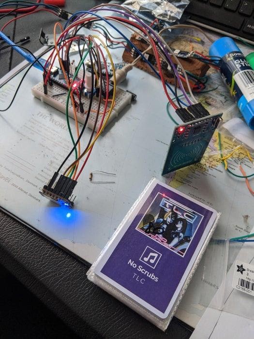
Assembling the prototype
I won't talk too much about this step of our work. Everything is pretty simple here. The core of the project consists of several parts:
- An Arduino Nano board that controls everything with the code we'll talk about below.
- The DFPlayer Mini module is a small electronic device that can play MP3 files from an SD card inserted into it.
- RFID-module RC522, which is used to read RFID-cards, receiving data from them, used to select the songs to be played.
- Buttons and volume control.
- Speaker.
I used a breadboard to assemble the components, and followed the Juuke assembly instructions that came in handy. Then I tested everything to make sure everything worked as expected.
Prototype testing
Step 2. Soldering
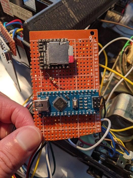
Components placed on the prototyping board
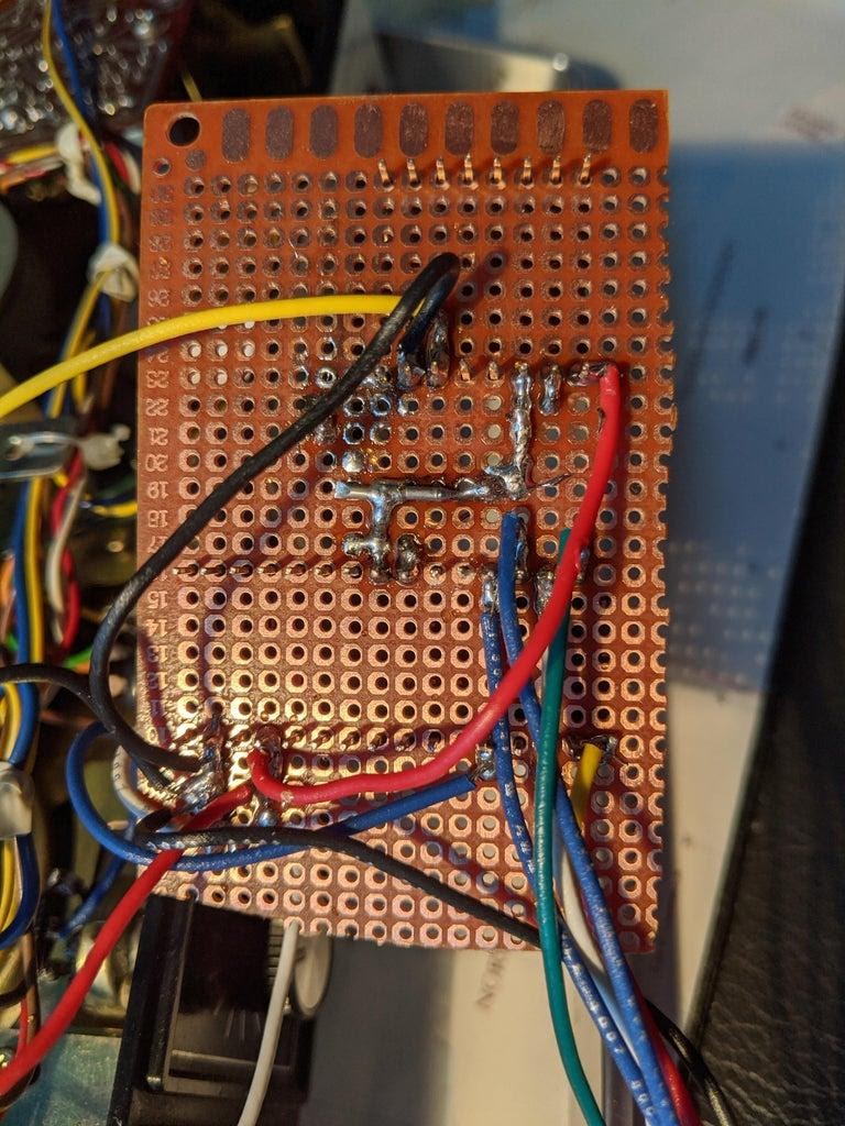
The reverse side of the board
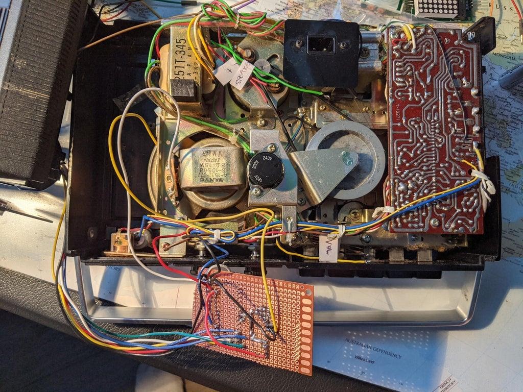
Connecting the board to a tape recorder
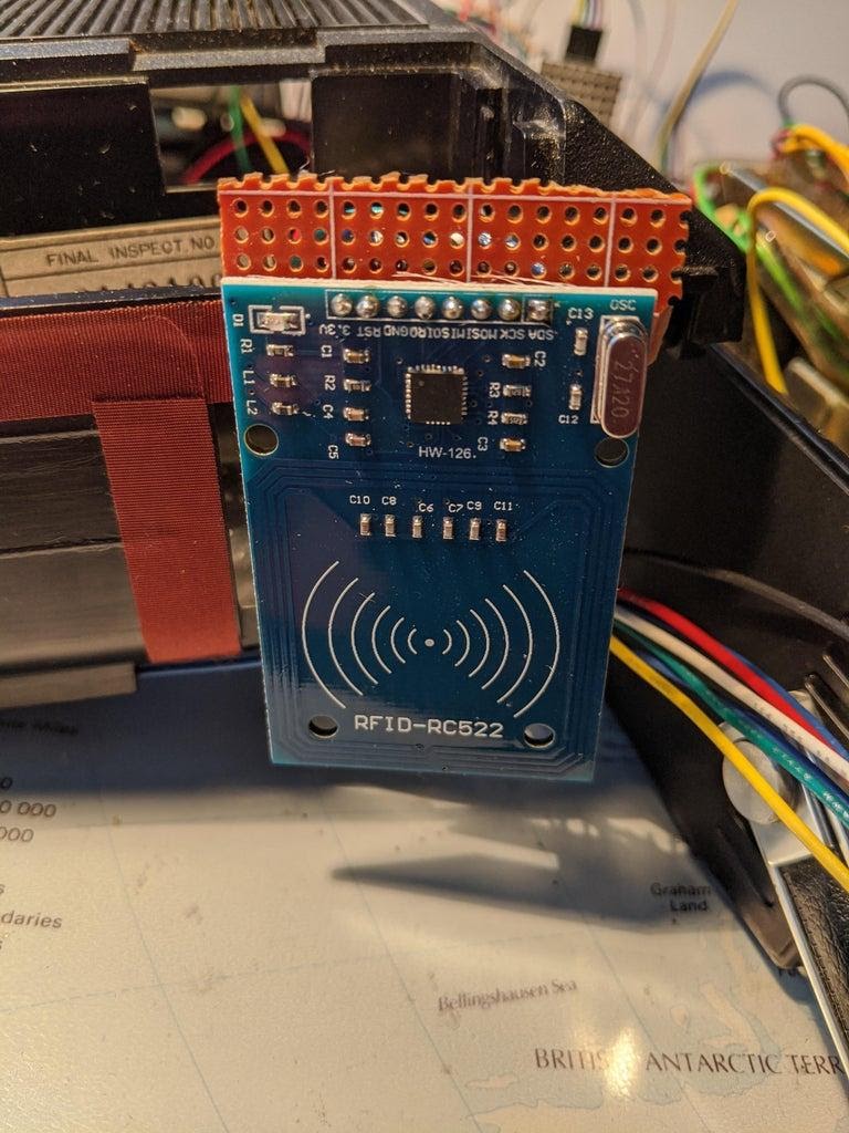
Board with RFID-module RC522 installed on it
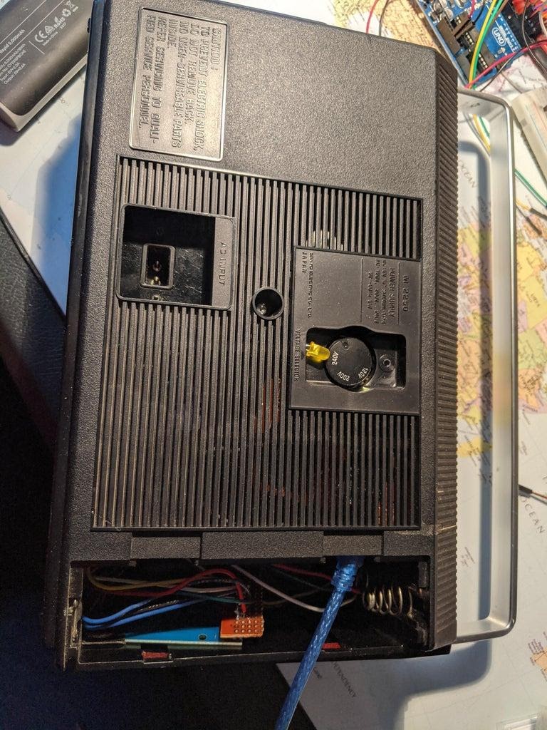
The board with RC522 is located in the battery compartment of the tape recorder, in the center of the image you can see the LED indicating "Side B" playback
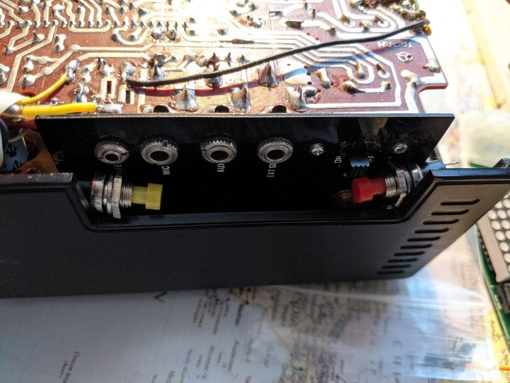
Buttons before soldering
After getting the prototype and how it works, I soldered the components of the device onto the prototyping board. Here I followed the diagrams prepared by the Ananords user, but made one small change. Namely, I added an LED. The "+" pin of the LED is connected to Pin 8 of the Arduino Nano board, and the "-" to ground. This LED indicates that Side B is playing. When "Side A" is being played, the LED is off, and when it is on, "Side B" is being played.
I opened the cassette recorder and found wires leading to the volume control and to the speakers. I unsoldered and labeled these wires with the appropriate labels attached to them. This allowed me to know exactly where they were leading.
I decided not to touch the rest of the tape recorder - in case I ever decide to restore it. I managed to fit the Arduino Nano and DFPlayer Mini on a small board that could fit in a tape recorder case. There, however, there was not much room for buttons and for the RFID module RC522.
On the side of the cassette recorder, I found a place for the buttons. Although it cannot be said that they are installed perfectly in the case, the design turned out to be quite solid, and the case itself did not have to be redone. This meant that if I ever decided to restore the tape recorder to its original form, I would not have to fill up holes in the case that could be drilled for mounting buttons.
I ran the RC522 wires through the holes in the battery compartment and installed the board with the RFID module itself in the same battery compartment, near the outer wall of the recorder case. I decided to do just that due to the fact that due to this there will be very little space between the outer wall of the tape recorder and the RFID module. The surface of the housing is also flat. This means that the RFID module will have every chance of successfully reading the card brought to the body.
When installing the LED, I passed its legs through small holes in the back of the case, and then soldered them to the corresponding wires.
In fact, this is my first experience of reworking an electronic device. And I solder for the second or third time in my life. But all the components of the device were reliably connected to each other and I was pleased with myself.
Step 3. Prepare RFID cards
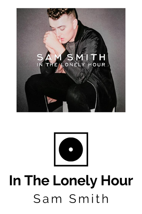
The cover of the card used to enable album playback
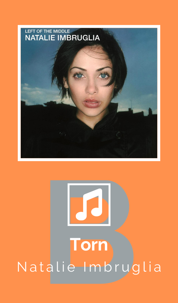
The cover of the card used to play a single song from "Side B"
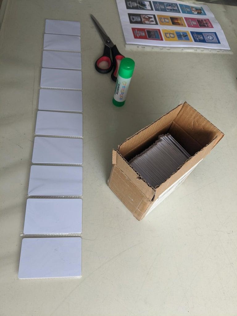
Maps and their covers
In order to prepare maps for work, you need to do two things:
- The cards need to be programmed by assigning numbers to them (there are instructions on this in the Ananords project). There are two ways. The first one is to do it automatically, then each next card will receive a number 1 higher than the previous one. The second is to set the parameters of the cards manually, using the window
Serial Monitor
in the Arduino IDE. - . , ( ) . Excel , , 1 100. « A». , « B», .
After the list was ready, I found the images that fit and made the covers in Canva. It is very easy to use this service, and the covers are neat, made in the same style.
To indicate whether a card is associated with a particular song or with an album, I used special icons. In the illustrations for this section, you can see the cover of the album card (with a disk icon) and the cover of the card, which includes a separate entry, with a note icon. In addition, I have placed a large B in the background of those covers that will correspond to the compositions placed on the "Side B".
I printed the covers on a color printer, cut them out and glued them to both sides of the cards using a glue stick (it doesn't matter where the cover for "Side B" will be applied).
After the cards are ready, all that remains is to upload the program code to the Arduino Nano and prepare the microSD card for work.
Step 4. Reviewing the Arduino Code and Preparing the SD Card

Folder 01 contains recordings that can be selected one at a time, while folders 78-99 contain albums
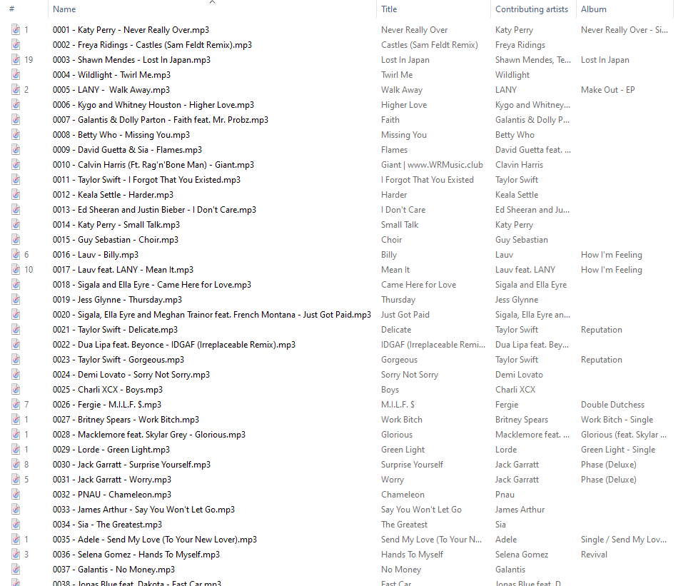
Folder Contents 01
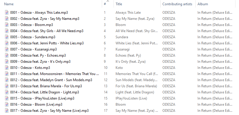
The contents of one of the folders with albums
The Arduino code and the files written to the MicroSD card are inextricably linked, since the program will not work correctly if the card is not prepared correctly. Therefore, this step of working on a project consists of several stages.
▍Preparing individual records
I ran into some difficulties using the Juuke project materials. They consisted in the fact that sometimes the playback of the wrong song was turned on, which depended on the MicroSD card inserted into the device. I researched this question and found out that I can rewrite the code and make the player play songs from a given folder. So I put all the individual songs in a folder named 1 and told the player to play the selected song from that folder:
myDFPlayer.playLargeFolder(1,number.toInt())
To play "Side B" I provided a code that, observing the state of the button, informs the player about the need to play songs, the numbers of which are calculated by adding 100 to the number of the card read by the RFID module. For example, if card # 22 is scanned and the “Side B” playback mode is enabled, then song number 122 will be played. If this mode is not enabled, then reading the same card will play song number 22. This is what the corresponding code snippet looks like:
myDFPlayer.playLargeFolder(1,number.toInt()+100)
Music file names stored on a MicroSD card must have a 4-digit prefix corresponding to the number assigned to the RFID card. For example, if card # 3 is assigned, then the name of the corresponding music file must start with 0003. And the song associated with card # 21 will be written to a file whose name starts with 0021. Songs for "Side B" are named similarly. For example, record 157 will be written to file with prefix 0157.
▍Preparing albums
Albums are organized in a similar way. The player can play records stored in a specified folder. Each album corresponds to a separate folder, the number of which coincides with the number of one of the cards. As a result, for example, you can scan a card with the same number to play songs from album # 90. Here is a snippet of the player control code:
myDFPlayer.loopFolder(number.toInt());
This is how I managed to achieve playback of recordings related to individual albums. However, there is a limitation that only the contents of 99 folders can be played. First, I set up the system so that the albums were in folders 89-99. But when I decided that my cassettes would have Side B, that meant I couldn't just add 100 to the card numbers, since the system didn't allow folder names in the 189-199 range. By that time, I already had 11 albums. As a result, I decided to find the name of the folder corresponding to "Side B" of the card by subtracting 11 from the card number. And so it happened that the additional albums fell into folders 78-88. In code, it looks like this:
myDFPlayer.loopFolder(number.toInt()-11);
All that I have told about the structure of folders recorded on a MicroSD card is reflected in the above screenshots.
In the project code, you can find comments on where you need to make changes related to the numbering of folders and files. This will allow you to customize the system for yourself.
▍Buttons
I, when comparing my project to Juuke, made some changes to the way the buttons work. For the sake of simplicity, I decided not to increase the number of buttons, which I also have two. But I wanted to expand their capabilities by handling short and long presses.
The program compares the time of pressing the button with the specified value (half a second in this case). If the button is pressed for a time that does not exceed these half a second, it is considered a short press. Otherwise, the system considers that a long press on the button was made.
The red button turns on or pauses the playback of the current song by a short press. Long press on this button causes the transition to the next song. A short press on the yellow button allows you to turn on and off the playback of songs "recorded" on "Side B" (the LED on the back of the tape recorder immediately turns on or off). Long press on this button "shuffles" the compositions.
To enable playback of the next song, I used the following code:
myDFPlayer.next();
For the B-side compositions, I used a special variable. This variable is set to a value
false
until a short press on the yellow button. After pressing, the value of the variable changes to
true
. This variable is used when deciding which songs to play. Entries with indices 1-100 are "Side A" and entries 101-200 are "Side B".
Look here for the code I was talking about . You can change it as you need.
Step 5. Final assembly and design verification
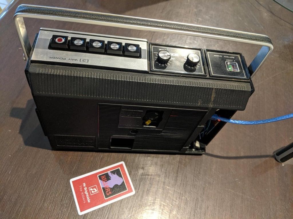
Finished project, rear view, playing a song from "Side A"
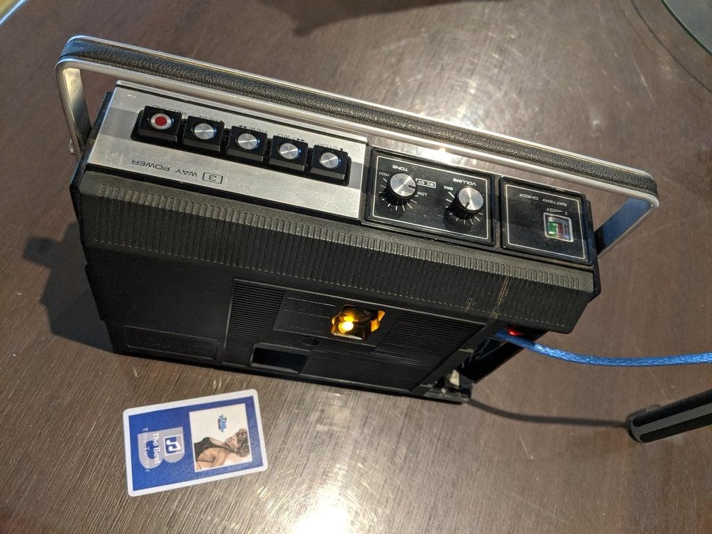
Finished project, rear view, playing a song from "Side B" (note the LED lit and the card with the letter "B" on the cover)
I removed all the wires into the case and replaced the back cover of the tape recorder. Then I connected the USB cable to an external battery, which is also located in the case (my player can work without being connected to the mains) and checked the system's operation with different RFID cards.
System test
Step 6. Listening to music
And now you can listen to music from new "cassettes" on an old-school cassette recorder.
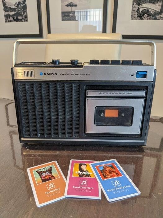
Finished project
Listening to Music
Planning to make an RFID controlled music player?
