I suggest that you familiarize yourself with the previously posted materials on the Starlink (SL)
project : Part 1. The birth of the project ‣ Part 2. SL network ‣ Part 3. Ground complex ‣ Part 4. Subscriber terminal ‣ Part 5. State of the SL grouping and closed beta testing ‣ Part 6. Beta-testing and service for customers ‣ Part 7. Bandwidth SL and RDOF program network ‣ Part 8. Installation and inclusion of subscriber terminal ‣ Part 9 service in markets outside the US ‣ Part 10. SL and the Pentagon ‣ Part 11. SL and astronomers ‣ Part 12. Space debris problems‣ Part 13. Satellite network delay and access to radio spectrum ‣ Part 14. Inter-satellite communication links ‣ Part 15. Rules of service ‣ Part 16. SL and weather ‣ Part 17. Second generation SL ‣ Part 18. SL in the COTM market ‣ Part 19. What's the future of SL
The appearance of the SpaceX UT-201 subscriber terminal for operation in the Starlink network was presented earlier, as well as its technical characteristics. In this chapter, we will look at its internal structure. Moreover, as soon as Starlink terminals went "to the people", those who wanted to disassemble them immediately appeared. The first one turned out to be a "miser" and did not break it, limiting himself to parsing the plastic and finding out the device of the electric drive (see video below)
I note that this gentleman has already appeared as one of the earliest testers of Starlink and, judging by the brown color of the box from under the terminal, he received it even before the official public beta testing from the very first batch, which kind of hints that he has unofficial contacts with SpaceX, perhaps that is why he did not break the terminal and show its internal structure.
However, another owner of the terminal from SpaceX, whose name is Kenneth Cater, did not regret $ 600 (the price of the terminal, including shipping and sales tax) and took it apart, which is called "to the last nail."
Below is a selection of photos showing the Starlink terminal structure: The
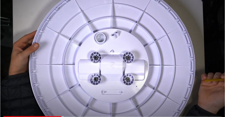
bottom cover is snap-attached:

Type of rod and block of electric motors:

Once again with the power plug for the electric motors:
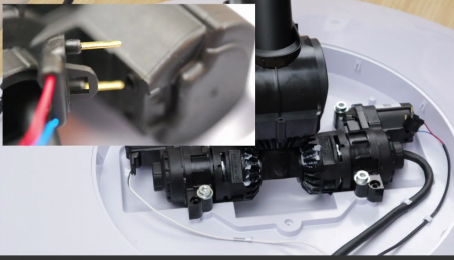
The original design of the gearbox, which allows turning on 1 or 2 motors to provide either a turn in a plane (2 motors work in different directions), or an antenna tilt (2 motors work in one direction).

The rod and the electric drive unit are fastened with screws to a plastic case with nuts pressed into it and can be easily changed if necessary.

Antenna view with a phased array.

It is non-separable and, after removing a part of the plastic case and reassembling, the terminal remained operational:

Further, materials from Habr are partially used here , many thanks to its author maybe_elf .
Kenneth Keiter disassembles the phased array antenna: "It was not possible to put the device back together, as most of its elements hold a solid layer of glue." Keiter had to literally tear off the antenna elements. Here is a diagram of the phased array device:
Photo: www.businessinsider.com
“Inside is a Power over Ethernet cable, GPS receiver, flash storage and H-Bridge drivers used to control the antenna's rotation and tilt motors. The antenna is equipped with an ARM processor and RAM to run phased array software. The microcircuits on the printed circuit board seem to have been made to order specifically for SpaceX. ”
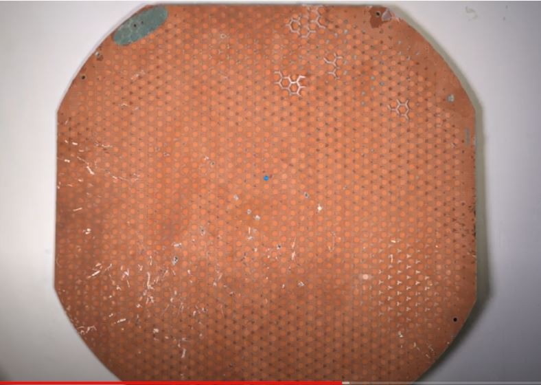
So, what we see when we take apart the antenna itself.
Antenna in a plastic casing before disassembling it:
A view of the phased array antenna without the plastic housing.

Antenna marking:

Then everything is glued together, you can only break it.
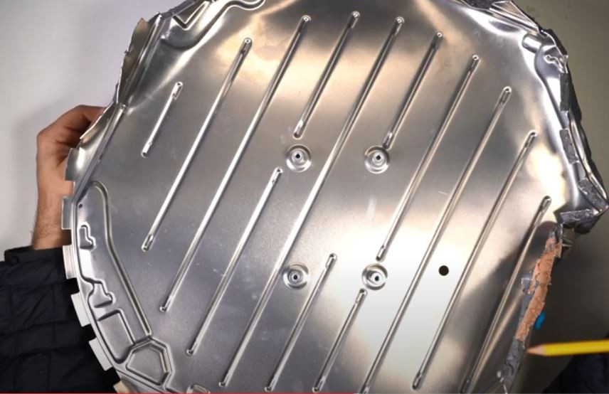
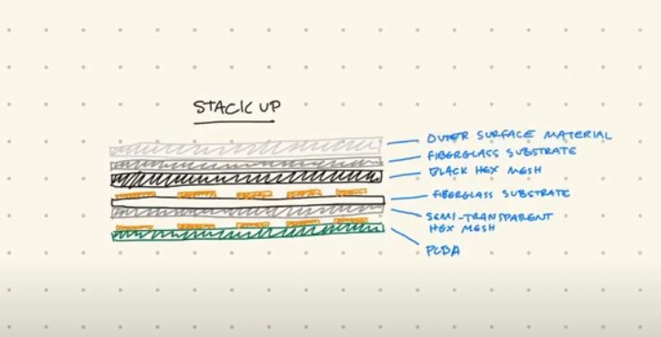
Internal aluminum body.

Spacers between them (blue dots). Apparently they provide ventilation and no overheating.

Under the second aluminum shield begins the board with the chips installed in it (industry sources talked about the Gallium Arsenide MMIC ( Microwave Monolithic Integrated Circuit)).

and they are the same MMIC, but larger.

View of the external radiating side of the antenna facing the satellite.
Type of radiating elements (first layer on the outer, "copper" side of the antenna)

Close-up view of the radiating element of the antenna:

Phased Array Antenna Structure As Seen by Kenneth Keiter - the author of the video on which the antenna is disassembled.
The composition of the electronics looks like this: one master processor that controls the controllers. (79 controllers are large microcircuits). Each controller serves 8 microcircuits. Each microcircuit transmits / receives a signal from 2 antennas (hexagonal elements). Thus, there are 79 controllers, 632 small microcircuits and 1264 active antennas, while all part of the antennas at the edge are not transmitting, according to experts, but are necessary to form a single structure of 6 elements around the active transmitting cell in order to avoid distortion of the radio signal.
For each microcircuit it is necessary to have in it 2 low-noise amplifiers (for signal reception), 2 amplifiers for signal transmission and a phase converter for each polarization (if the Terminal could use both polarizations simultaneously, which is unlikely. -Down Converter & Mixer Circuits

Description: “Caveats, details and simplifications of the attached model:
- A stacked 4 element design with a single driven element is modeled. Ground plane, driven element, solid parasitic element (all part of the main board), and slotted parasitic element on the second board.
- The ground plane is modeled as a simple planar surface with no defected structures except for the pass through for the driven element feed.
- The driven element is modeled as a simple square with featureless edges. Many square driven elements actually have clipped corners or other cuts.
- The driven element is modeled with a centrally located feed to simplify the model. Many patch feeds are off center. Some driven elements have two or more feeds to create alternate or circular polarizations.
- The driven element is shown twice, the one two the left is flipped to show the feed on the bottom.
- PCB layers A, B & C are the top three layers when viewed from the antenna (not chip) side of the board. Layer C is the visible one.
- Dimensions are approximations based on eyeballing images from the video. PCB layer and trace thicknesses were picked to be recognizable, and are prob
One of the most hotly debated issues among satellite communications specialists is the cost of the antenna.
Business Insider, SpaceX . 1 $2,4 STMicroelectronics. , SpaceX $2400. SpaceX - $100 - $500 , , . , SpaceX « » $500. , .
Kaul Pradman, President of Hughes Network Systems (the world's largest satellite terminal manufacturer and satellite Internet provider in the US, Brazil, India, etc.), during a conversation with EchoStar investors suggested that the Starlink terminal is likely to cost SpaceX from 1000 up to $ 1,500 apiece.
And Tim Farrar (USA), a telecom expert and longtime critic of the Starlink SpaceX project, asks a mocking question to American satellite Internet providers (ViaSat and Hughes Network System):
Ordering 1 million terminals at $ 2,400 each and selling them for $ 499 poses one overarching question for other satellite providers: can SpaceX remain ineffective longer than you can remain solvent?That is, which of you, traditional providers or SpaceX, will run out of money faster, and who will go broke sooner ??