lecture was almost 2 hours long, so it's probably better to watch it directly on Youtube; there is a table of contents in the description of the video. The video will be followed by an abbreviated text transcript (special for Habr).
Happy viewing or reading. :)
Description of the problem and concept of the solution
Let's start with the initial data. We have an ordinary scanner (in my case Canon CanoScan LiDE 120) that connects to the USB port of the computer and can scan into the computer. But here, for example, a second computer appears, and with the general need for scanning, switching the scanner between computers every time is inconvenient. What to do? Yes, now there are network MFPs, but for some reason this is not an option for us.
To solve the problem, we essentially need to equip a separate place for the scanner, organize a network drive, connect all the computers on our home network to it and teach the scanner to scan to this same network drive. The user in the process of scanning will be near the scanner, press buttons and change the scanned sheets; he does not need to run to the computer every time to give a command to scan. And then, when everything he needs is scanned, he will go to his computer, copy or transfer the scanned files from the network drive to himself and will continue to work with them.
So, we choose a place to place the scanner, we bring a cable to it from the router of our local network (WiFi is also possible, but we will leave this for an optional), we put an outlet for 220V power supply - and what next?
In theory, the scanner needs to be connected to a computer. But buying and installing a separate computer for these purposes is expensive and not justified. Well, he will need a keyboard and a mouse with a monitor, they also need a place. At the same time, we have nothing special, we scan mainly one format (A4). So let's look towards something more portable.
In our project, we use a single-board computer Raspberry Pi 2 Model B. Although it is not new and not very powerful, its power is enough for us for the task, it does not really consume energy, well, GPIO will come in handy.
For those who immediately want to repeat everything on the basis of the existing scanner, I recommend that you first go to the SANE project website, go to the list of supported devices and make sure that the specific scanner model is adequately supported by the project. Otherwise, efforts and, possibly, money can fly into the pipe. Moreover, it may be worthwhile to organize a machine (virtual or real) with Debian 10 (more precisely, the current version at the time of checking the version from which the Raspberry Pi Foundation made the operating system) and sane out of the box and check the work using the scanimage utility; if everything is normal, then it will probably work on raspberries.
Auxiliary Necessary
As for the power supply of the raspberry and the scanner, in the demo project I use a regular two-amp MicroUSB charger. But, if the raspberry is supposed to work around the clock, then I do not advise using them. This is not their task, and it is not a fact that a particular charging will not fail if it does not give so little current for a long time in 24/7 mode. It is better not to save money and take either a proprietary power supply unit, or adapt another suitable for such work.
Also, I do not recommend connecting the scanner with a USB cable of a long length or of whatever origin. This is from more than six months of operating experience; a surprise can happen at the most inopportune moment.
As for the "disk" memory - in raspberries, as you know, microSD cards are used. The tenth Raspberry Pi OS fits on a 4 gig card. But we will still have decent installable software there, plus a network folder for scans. So we focus on at least 8; 16 are used in the project. Also, for the initial recording of the OS image, you will need a computer with a card reader, into which the card can be connected. I used an adapter for an SD card reader built into the laptop.
We also need a body. There are a lot of options. In the shown variant, I used a non-original case of increased thickness; this made it possible to mount a circuit of two buttons and an LED provided by the project on the top cover (more on this later), and the height of the case was enough for buttons, and a raspberry, and BLS connectors for connecting to the GPIO pins. This body is made of plexiglass. This is how it looks with the assembled circuit, but without the raspberry:

Now I use this case for debugging and demonstrations, and in the combat version the raspberry is attached in a dedicated electrical panel along with the power supply and is used at the same time for another task, and the circuit is mounted in a separate small case, which is connected to the raspberry with a four-core flat telephone cable.
Another problem with raspberries is heating the core. If you plan to work around the clock, we glue a small radiator with something suitable heat-conducting.
Preparing a memory card
Let's start preparing the memory card. Recently, the Raspberry Pi Foundation not only renamed Raspbian to Raspberry Pi OS, but also released a program called Raspberry Pi Imager for Windows, macOS, and Ubuntu. Download this program, install it on your computer and run it.
First of all, in the program window, we will make Choose OS. There are many options. By default, Raspberry Pi OS (32-bit) is offered, but it is with a desktop, and for two, the desktop is so-so. Therefore, we go to Raspberry Pi OS (other) and select the lite option there; we hardly need anything other than the command line. Then we put and select a memory card and write an image on it. This process is shown in the video at 00:12:15 .
Initial setup
You can put the memory card in the raspberry and go to its setting. To do this, in addition to power, a network with the Internet and a scanner, we need to connect a USB keyboard and a monitor with an HDMI cable (for the fourth generation of raspberries, there is MicroHDMI). We connect the power supply last. And remember about safety when working with open conductive parts, especially if the raspberry is not in the case, and the power supply is questionable in terms of electrical contact with 220V.
Turn on, boot, log in with the default pi login and the raspberry password. The setup process in the video starts at 00:18:43 .
First of all, be sure to work out sudo apt update and sudo apt upgrade. At the time of recording the video, the repository offered to update 30 packages, although I recorded the image of the memory card immediately before the initial configuration. Apparently, it is not collected every time the repository is updated.
Further, if desired, we solve the problem of squares in the console instead of Russian letters. We call sudo dpkg-reconfigure console-setup and go through the menus. We set (or leave) the following parameters:
- Encoding to use on the console - UTF-8
- Character set to support - Guess optimal character set
- Font size - 8x16
We reboot for the first time. We do this in a regular way, via sudo reboot. Log in again, run sudo raspi-config and proceed to the initial setting of the parameters. We do the following tasks in it:
- ( : System options — Password )
- SSH (Interface options — SSH)
- (Localisation options — Locale; en_GB.UTF-8 UTF-8, en_US.UTF-8 UTF-8 ru_RU.UTF-8 UTF-8, )
- (Localisation options — Timezone; , )
- (Advanced options — Expand filesystem).
After that, select Finish. The program will offer to reboot, which we do.
Then we log in again (this time with a new password), go to sudo raspi-config, select Localization options and then Keyboard. The keyboard setup program will already write in Russian.
In the keyboard model, as a standard, we select "Ordinary PC with 105-key (Int.)
In the layout, first select" Other ", then" Russian "and then the option (just" Russian "or some more suitable for the existing keyboard).
Next, select the method for switching layouts and other different keys, if you want. Everything will switch quickly enough. It remains in the main raspi-config menu to go to Finish. We will not return to this utility again.
Installing and configuring additional software used by the project
Do sudo apt install wiringpi samba sane. I added mc to this list (and to the lecture) and show how to work with him, but this is a matter of purely personal preference, I do not impose on anyone.
Then (preferably in most cases) set the permanent IP address to the malinka. I think it is better to do this on a router, but if this is not possible, you can set static network settings by editing /etc/dhcpcd.conf after the comment Example static IP configuration. The dhcpcd package is included with the Raspberry Pi OS out of the box, you don't need to install it.
The next task is to create a directory for storing scan files. I chose this case and created the / var / scanned directory. This directory needs to be set such permissions so that samba can work with it.
Now, of course, we are configuring samba. We go to /etc/samba/smb.conf and register the global settings and the section with the data of the new network resource and the path to the directory we created there. The video shows it at 00:41:51 . But, of course, the specifics of the network can give certain differences from the settings given there.
After configuration, it is strongly recommended to reboot the raspberry and check the network drive from the computer. From there, in most cases, you will need full access to the files in the directory.
Before the transition to needlework and programming, we have two tasks left - to decide on the iron part and first figure out the parameters for the scanning program.
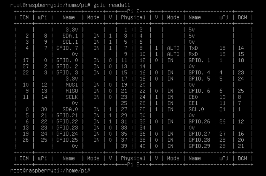
Let's start with the iron part. To do this, run gpio readall. Malinka will display the numbering of the pins on the GPIO connector in the Physical columns and their purpose in the Name columns. For the circuit, we need three GPIO ports and one common wire (in the Name column, it is called 0v; there are a lot of them on the connector, but we don't need so much, just choose any one of them). We write down their names and numbers on the connector. For myself, I chose GPIO.1 at pin number 12, GPIO.2 at pin 13 and GPIO.3 at pin 15. I will connect the common wire to pin number 9.
Now let's decide on the scanner, which we already have connected to USB. Doing sudo sane-find-scanner. If the scanner is not visible with this utility, there may be a problem with the scanner, raspberry, cable or power supply; this needs to be addressed separately. Now do sudo scanimage –help | less and see the options allowed for our device. For myself, I'll write down the options l, t, x, y, resolution and format. These options will go to the command line of the scanning program.
This completes the initial setup of the raspberry. Before assembling the circuit, the raspberry must be turned off. This, if anyone does not remember, is done with the command sudo shutdown –h now. After a while, the image on the screen will disappear, and all the LEDs on the raspberry will go out, except for the power LED. This will mean that the system has finished working, you can turn off the power and start handicrafts.
GPIO in raspberries is only digital (that is, two-level 0 and 1) and can work in three modes: just an input (the mode is called in), an input with a pull-up resistor with a resistance of 50-65 kilo-ohms (called up) and an output (called out). We will use the last two modes.
As I wrote earlier, we will need to connect two buttons via GPIO (let's call them "Start" and "Stop") and an LED. Naturally, to limit the current, you will need to connect a limiting resistor in series with it; I chose an output resistor with a nominal value of 2.2 kilohms and a dissipation power of 0.25 W; this is usually enough. The connection diagram is as follows:

Based on the use of the up mode, remember that when the button is pressed, the value 0 will be read from the GPIO input, and when released - 1. Both buttons are normally open, without latching.
I will not dwell on the details of the execution here, especially since I previously showed a photo of the finished case, where everything was already there. For safety reasons, I would only recommend choosing buttons whose outer parts are all plastic so as not to stick out with exposed conductive parts. I connected to the GPIO pins with single-pin BLS connectors, similar to those used in computer cases; for this demo, I simply took a bunch of wires from Arduino projects with suitable connectors, selected four multi-colored ones, bit off unnecessary ends, cleaned and soldered to the details. Another option is to use a 40-pin double-in-line flat cable connector or even a piece of an old IDE cable from hard drives or CD drives, if anyone has anything else. This option, by the way, is also suitable for standard height cases;they have a slot for such a loop for output to the outside.
Well, and also, I remember, I suffered with the fact that on the raspberry boards (in any case, 2 model B and 3 model B) the numbering of the pins of the GPIO connector is not indicated. I'll fix it now; these two models have no differences in this regard.

Implementation of the software part
The software part is implemented (tadam!) In the form of two bash scripts - a config and a working script itself. A detailed explanation of the flowchart algorithm and implementation is in the video at 01:08:30 . I don’t think it makes sense to go into details here; the source codes of the scripts can be downloaded here and studied at your leisure.
The launch of the main working script is written to startup in /etc/rc.local. The only thing - I had to first register the change of the working directory to the directory with scripts. But there is nothing terrible here, it does not interfere with working further. And, of course, do not forget to add the & icon after the launch command, otherwise there will be problems with booting the system.
Well, then it remained actually only to show the actual scanning process, as well as ssh connections and tweaking the parameters - the way it was with me. You can watch it in the video at 01:41:04 .
Somehow it happened. In the combat version, of the differences, only scanning goes to a separate NAS, respectively, the scripts are slightly changed. And so, I think, scans can even be sent to the messenger with a bot somewhere, there would only be a desire to understand the corresponding API and do something like that on curl. There are plenty of options. Good luck with the implementation. :)