An overview of the typical solar problems and what to look out for before it's too late. Based on an analysis of 50+ home solar stations of various ages.
Introduction
The main testing methods which may show no qualitative changes in the work of both the solar station and the panels are thermal imaging diagnostics and testing using electroluminescence.
Quantitative measurements include measuring the volt-ampere characteristic of the panel (IV Curve), but about that another time.
This spring, finally, all the work was completed, my https://habr.com/ru/post/465133/ stations were completed and it was understood that it would be nice to check that everything that was acquired by back-breaking labor was built.
Having heard enough about possible variants of defects in solar modules, I decided to delve deeper into the topic and share my experience.
Thermal imaging survey of solar stations
Thermal imaging was chosen as the simplest, though not the most budgetary solution. There is a lot about thermal imagers on Habré, and a lot has already been written on the Internet, but after reading it, including
https://habr.com/ru/post/457808/
https://habr.com/ru/company/lamptest/blog/402071/
my choice fell on the FLIR ONE Pro Gen3 (Thermal resolution 160 × 120, Optical resolution 1440 × 1080), which was more than enough for my purposes. I bought it slightly in a second-hand condition, for $ 400.
Running a little ahead of myself, I will say that I could not even dream of the best for this money, I recommend it.
My stations were quite far away, and given the quarantines and other "amenities" of the year, there was no way to go there quickly, and the desire to try something other than cats
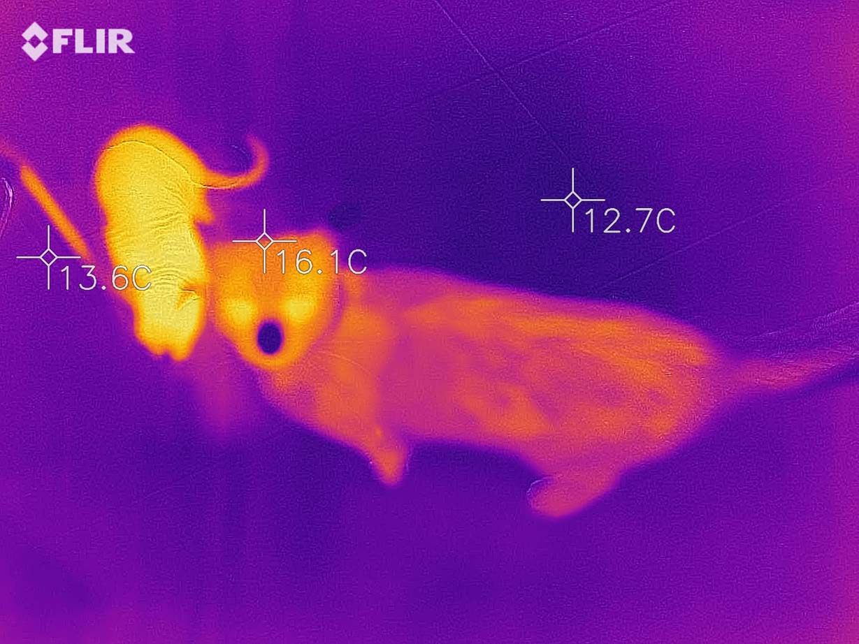
. , , .
, 50 , 5- , .
, , "".
, -
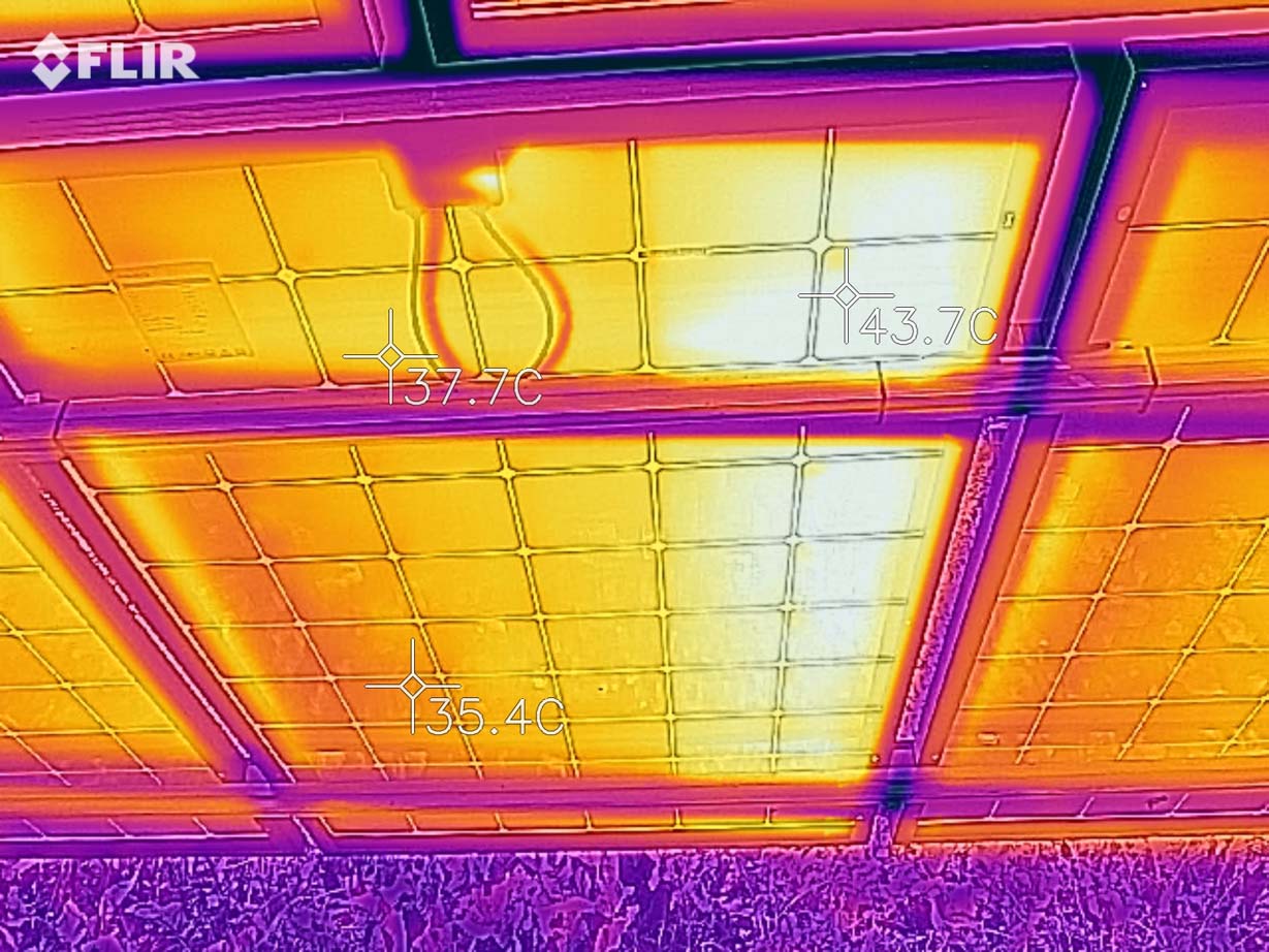
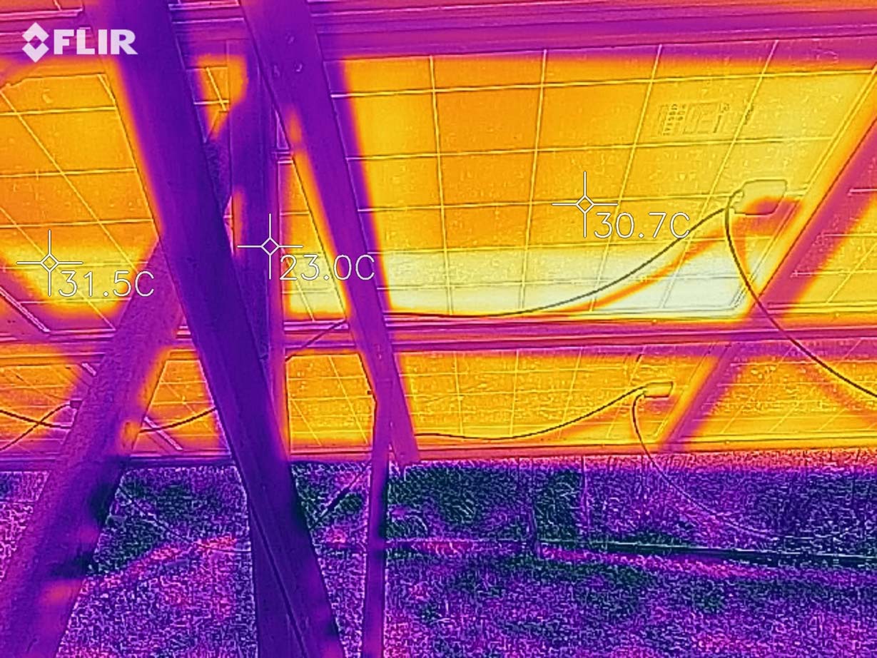

.
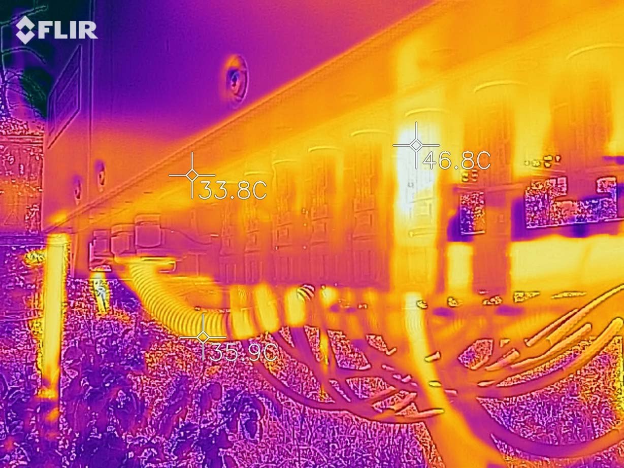


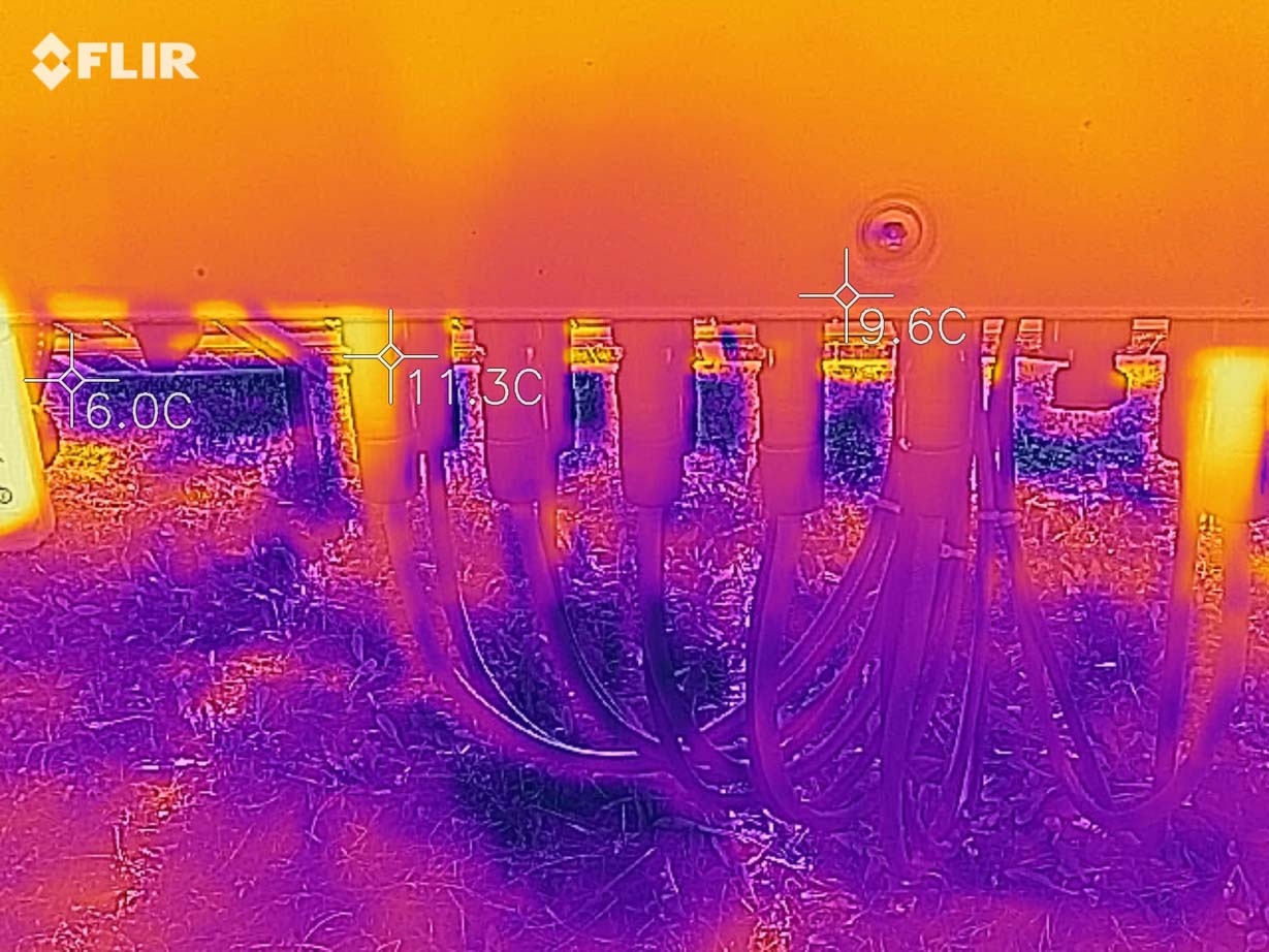
, . , , . (junction box), , .
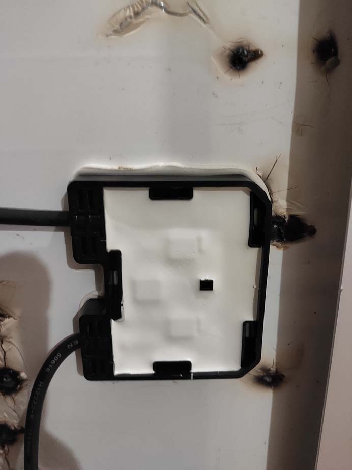
.
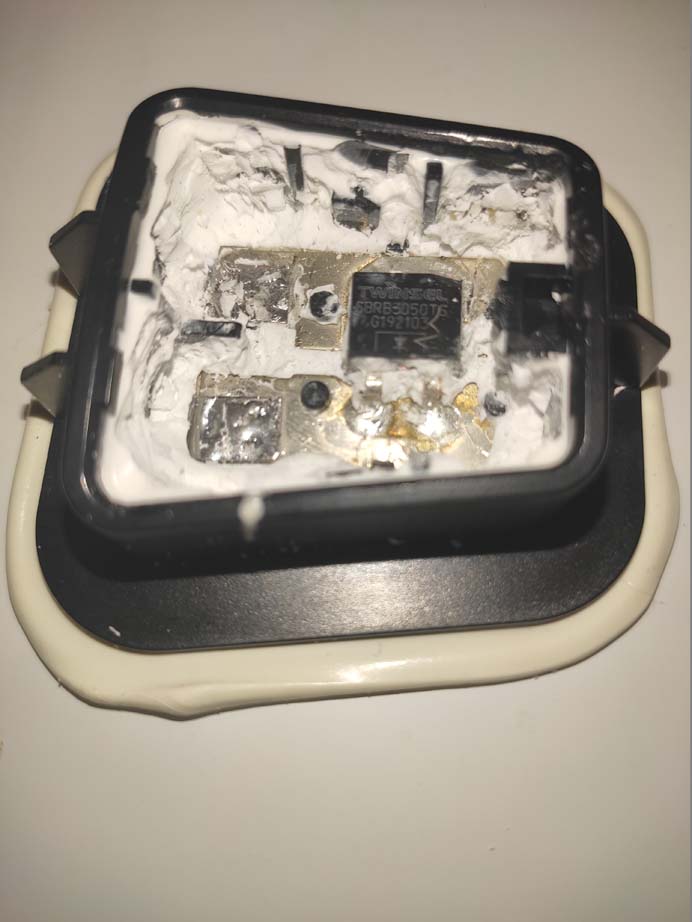
, ( 1/3), “” . , , . 33% , . .
, , , . , , , (, , ).
, - , .
, , .
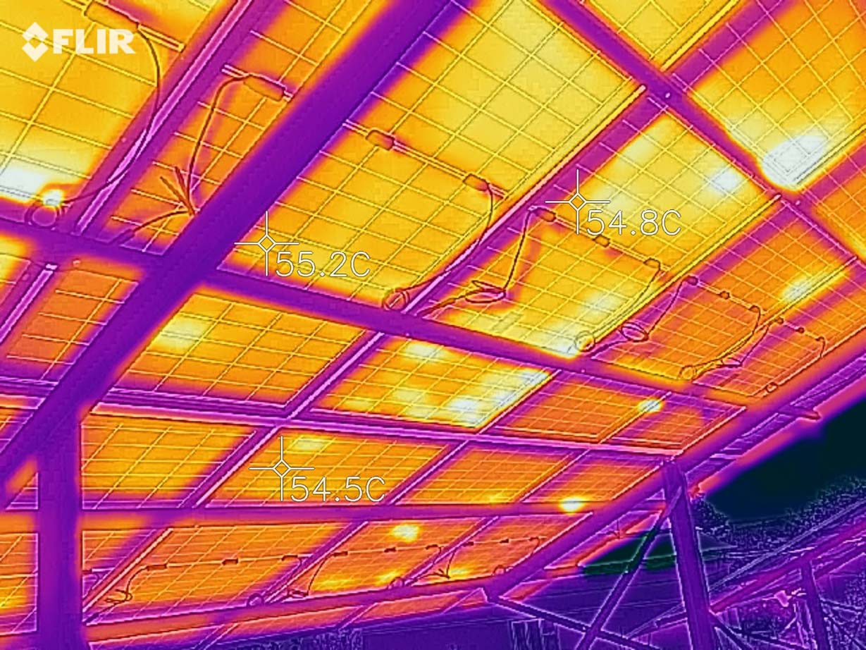
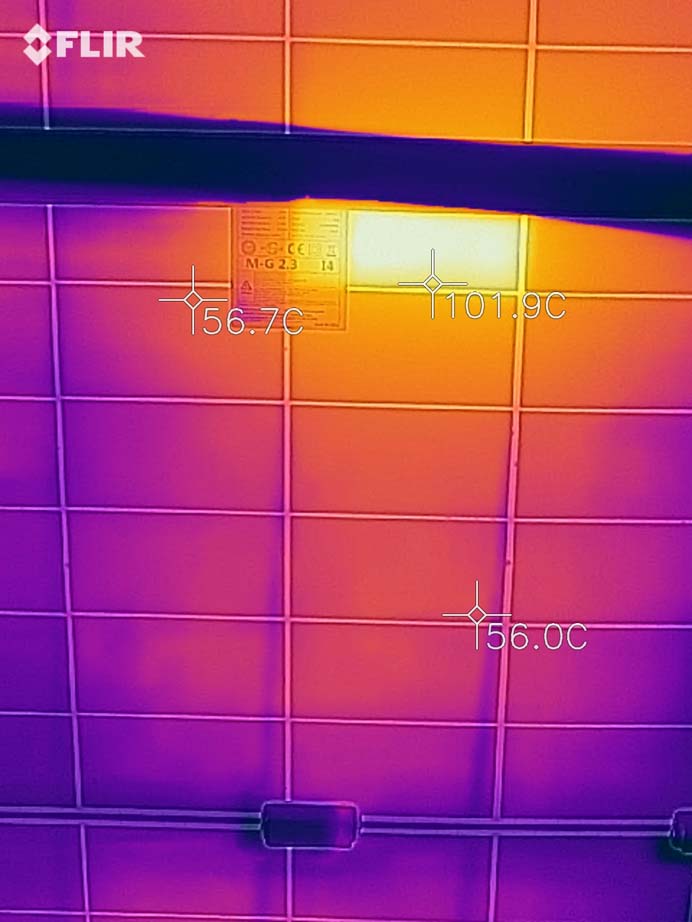
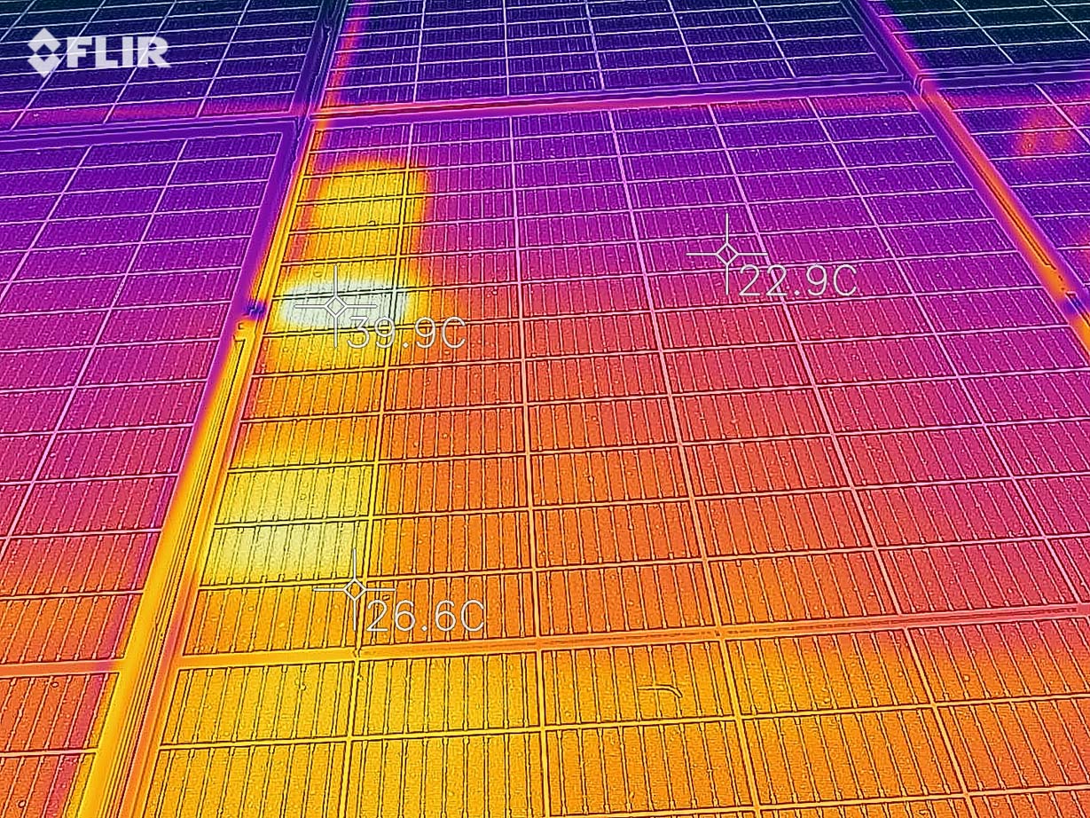
- , ( ), . , , .
, , . , . , - .
.
, , .
(EL imaging solar cells), EL-, .
, (Near Infrared), .
, , , . , , , ..
, , :
- / . , . , , - 80V 10A, ~80$.
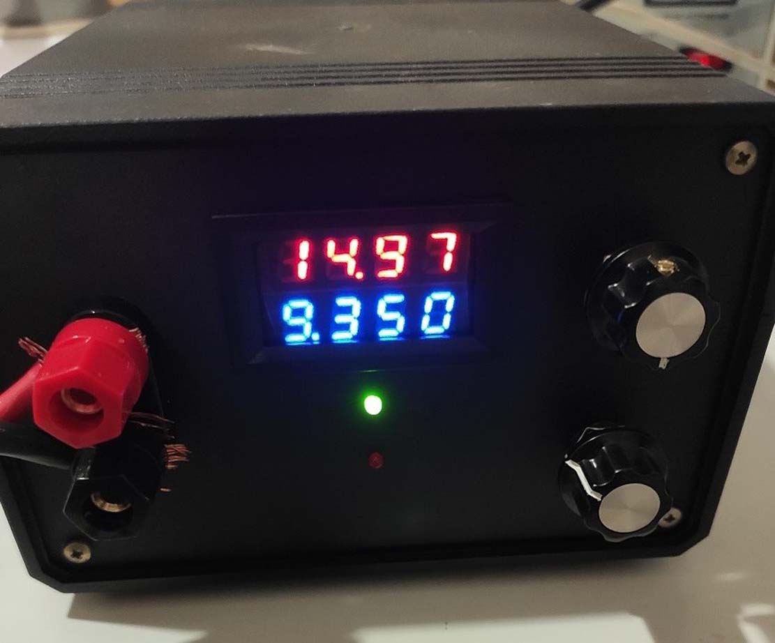
, , 1000, . , , .
- , , (NIR).
, , Raspberry PI, . - InGaAs sensor.
CCD . ~950 . - , .
, , .
Olympus µDigital 800, . , . , .
, , . , .
CCD - , , , , . “ ”, , 10- , (WIFI, pc live view, ..)
- BSI-CMOS. , . , CCD CMOS, .
.
, , . https://www.dpreview.com/products/search/cameras#!
, , . “” Samsung NX mini, BSI CMOS 1″, Wi-Fi, RAW, 110$ . Wi-Fi , . 10 , .
, , 2 , 0,5 . . , .
, “ ” - , " " . , , , , , . , , 2 , .
, , , , , .
, .

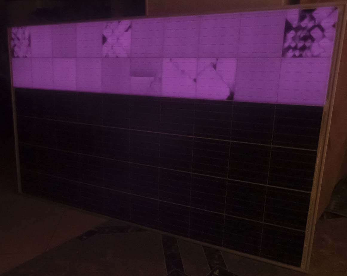
, .

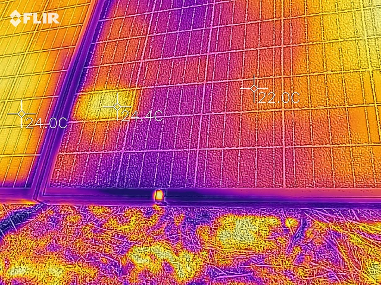
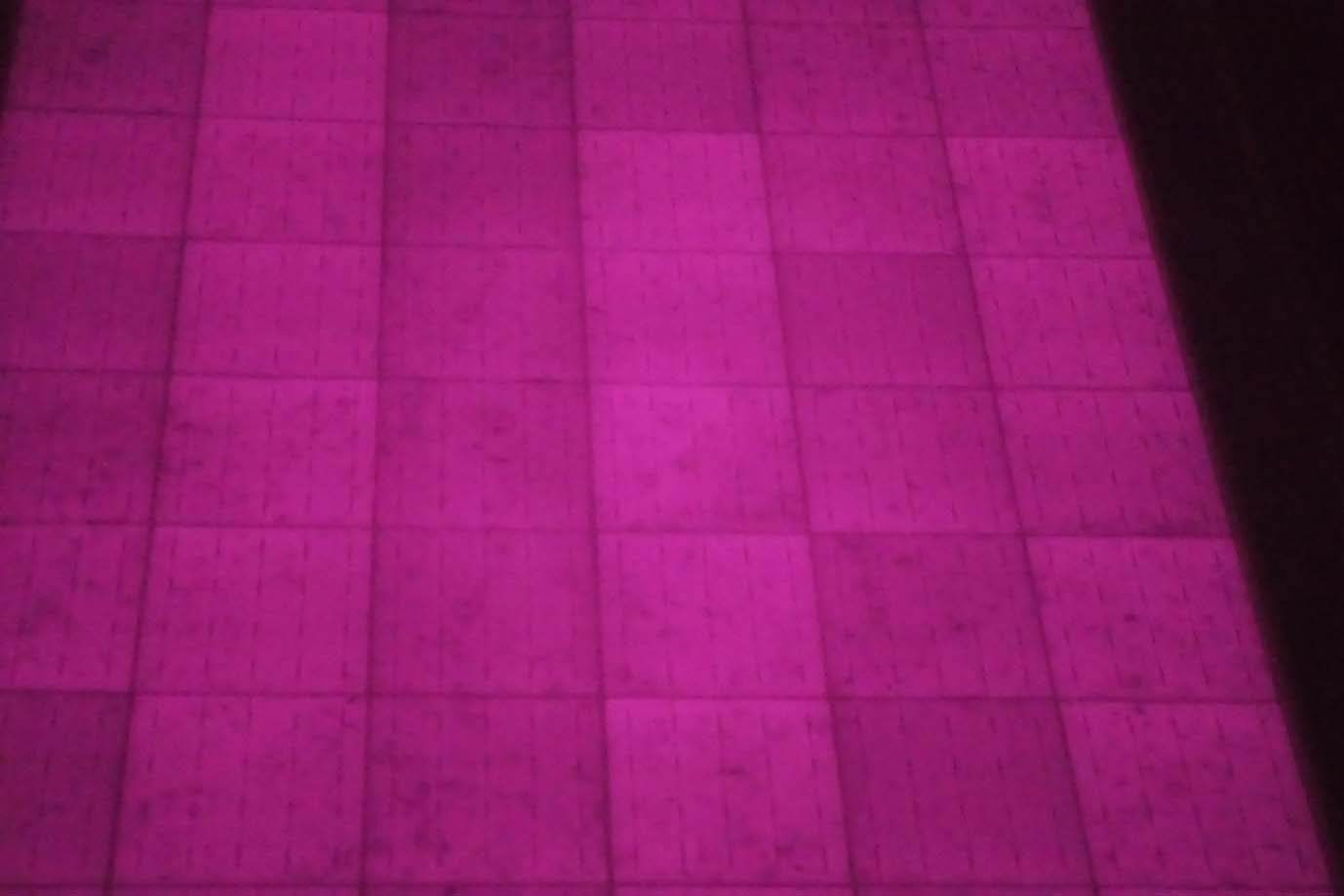
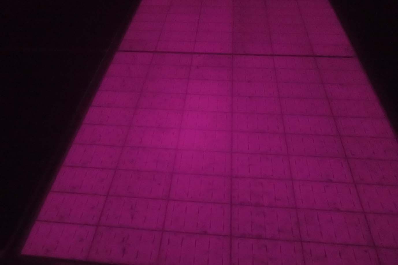
, .
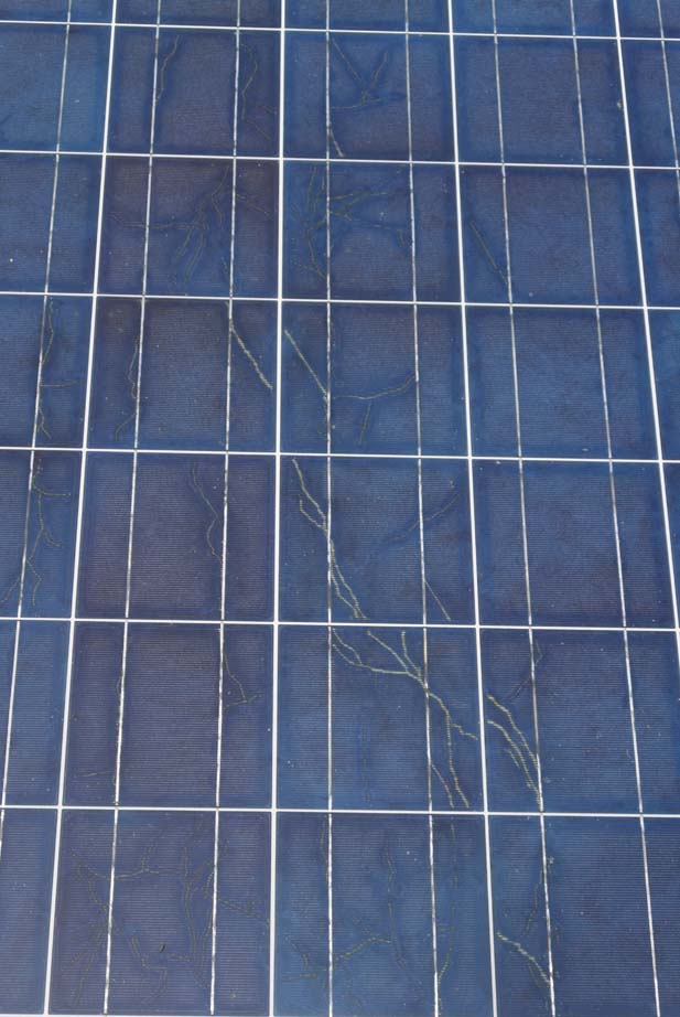


, - , , , - , .
- , - (IV Curve). 1000$, , - https://www.instructables.com/IV-Swinger-2-a-50-IV-Curve-Tracer/, . , .
, , . , . , " ".
, , .
, / ,
https://iea-pvps.org/wp-content/uploads/2020/01/IEA-PVPST13-012014ReviewofFailuresofPhotovoltaicModulesFinal.pdf
https://iea-pvps.org/wp-content/uploads/2020/01/Review on IR and EL Imaging for PV Field Applications by Task_13.pdf