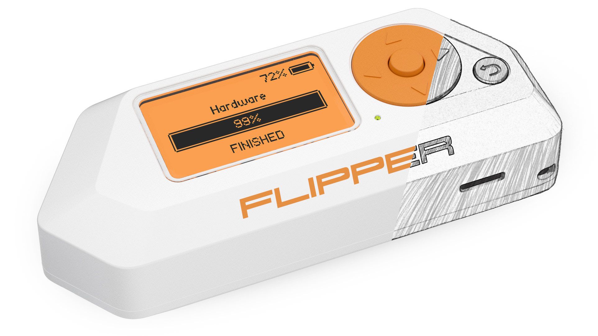
Flipper Zero is a tamagotchi form factor pocket multi-tool for hackers that we are developing. Previous posts [ 1 ], [ 2 ], [ 3 ], [ 4 ], [ 5 ], [ 6 ], [ 7 ]
Hardware development is very different from software development. If you can make edits in the software at least every day, then in the case of hardware, for each change in the board, you need to start a new production cycle of test samples and wait for them to arrive. Therefore, an important stage in the production of electronics is design freezing. This means that the list and component ratings are no longer changed, and changes are no longer made to the circuit board and case design. Then you can order production.
For the last month and a half, we have been actively working on hardware validation, trying to cover all use cases with tests, and now we are almost ready to load the BOM and start producing the first 50 Flippers in the EVT (Engineering Validation Test) format. Devices from the first batch will be shipped to contributors involved in the development.
Supply system
The power subsystem in Flipper is much more complex than it might seem at first glance. We use several independent 3.3V power circuits for the internal periphery and 5V for the NFC oscillating circuit and the output of the external GPIO comb.
Main components of the power system
- BQ25896 - battery charge controller, controls the charging process
- BQ27220 - (fuel gauge) meter of incoming and outgoing energy, monitors the condition of the battery and allows you to determine the real capacity of the battery, taking into account wear
- 2x TPS62743, LM3281 - DC / DC converters, they are also pulse converters
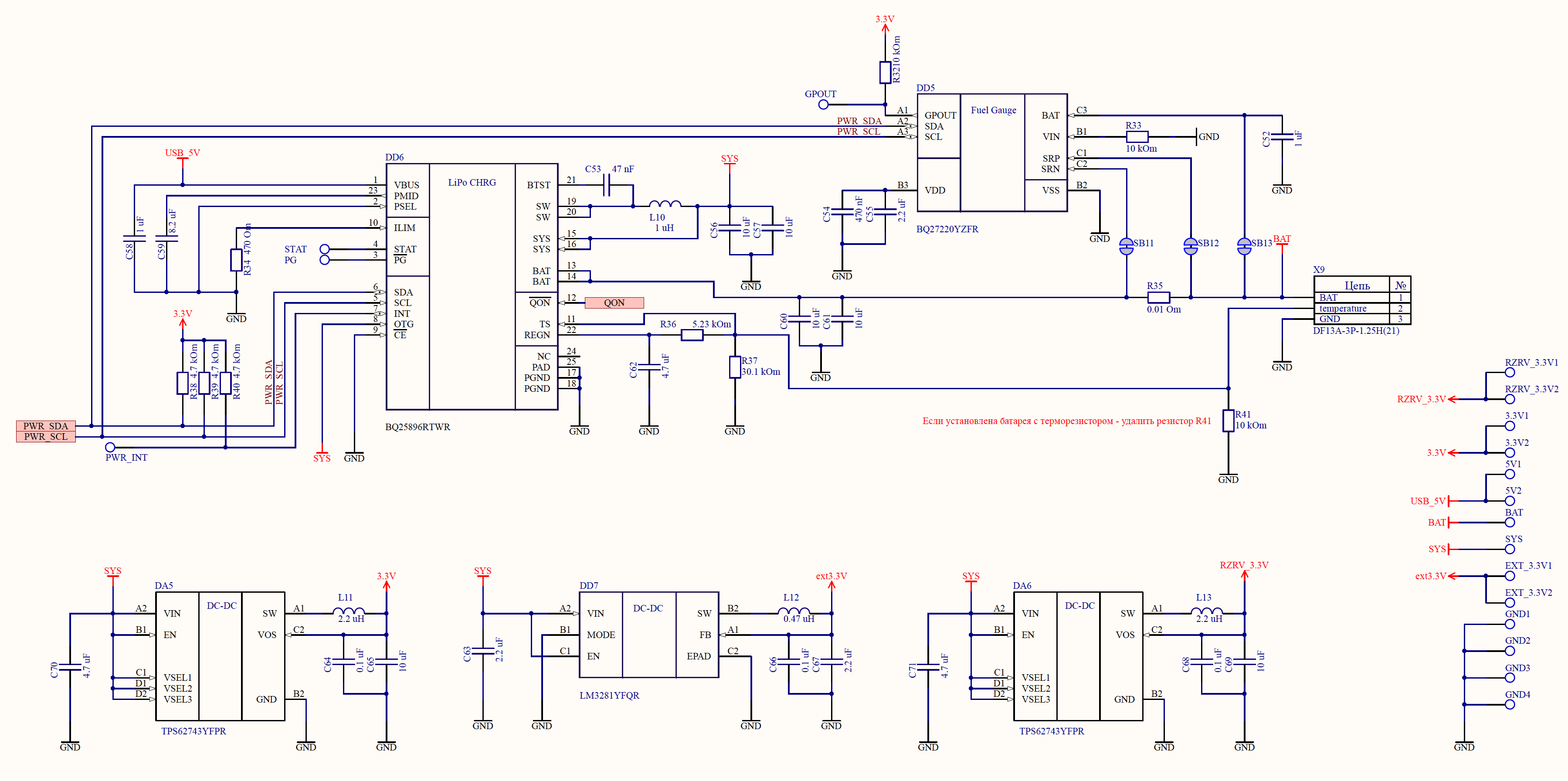
Flipper's power system diagram (clickable)
To debug faster, we released boards with a power system in the form of separate modules that were connected to Flipper. This way, it was possible to make changes independently of the main board, because the power system changed much more often than the main board.
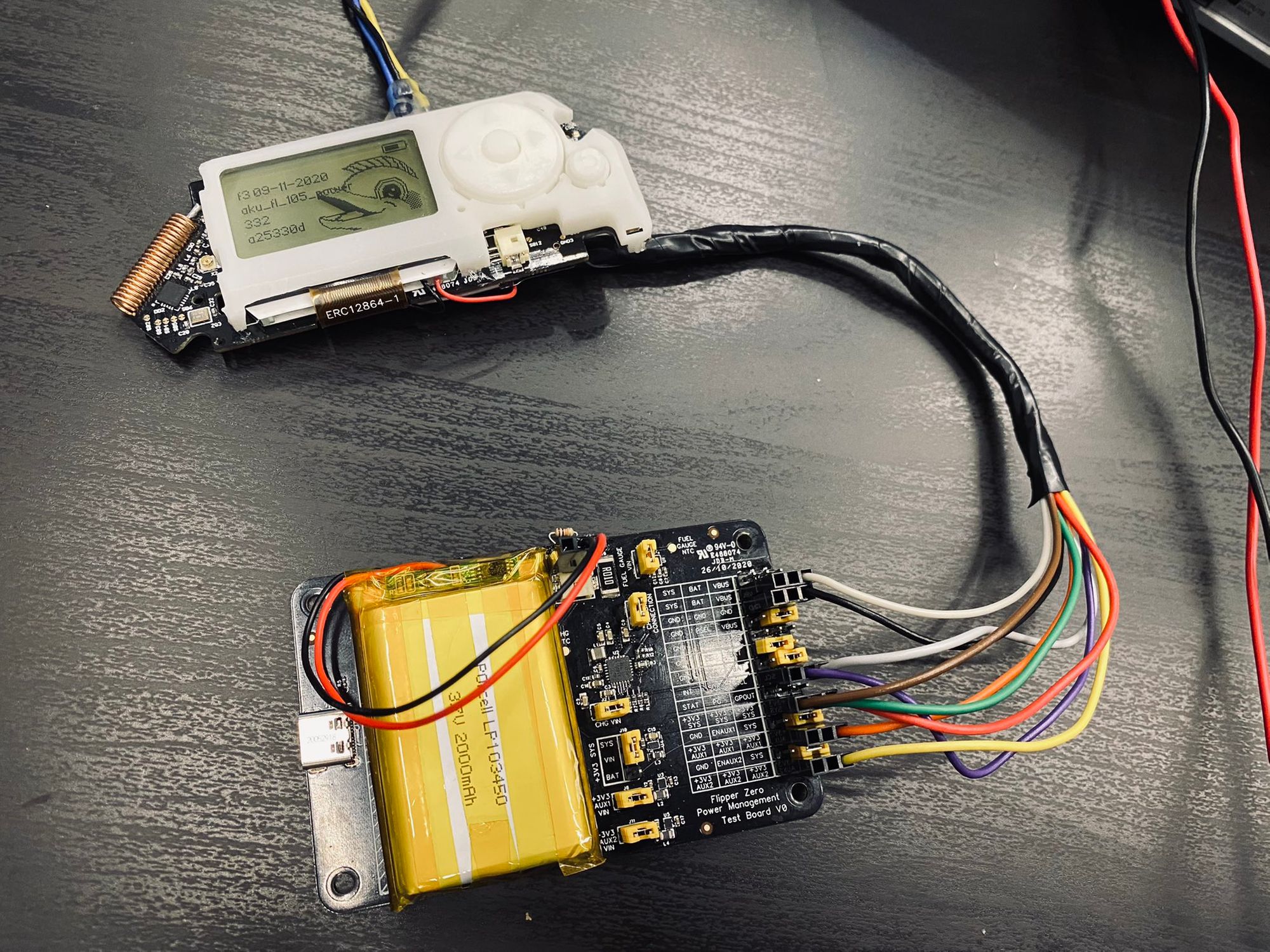 Flipper connected to external power board
More power for infrared
Conventional infrared remotes have huge IR output diodes that can emit at high power, but due to their size, we cannot supply such diodes to Flipper. So we had to find a way to get enough power from the SMD LED transmitter.
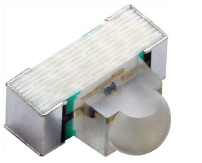 Infrared SMD LED VSMY14940
We decided to use 3 VSMY14940 LEDs. They have a narrow radiation pattern and 82 mW / sr power per diode.
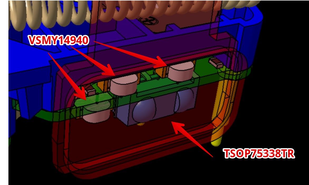 New IR port design: three diodes for transmitting and TSOP for receiving
IrDA tests
Dual Band RFID Antenna
To combine RFID 125 kHz and NFC 13.56 MHz on one bottom surface, we had to work hard. To do this, we took the antennas to a separate board and combined them on one PCB, placing one inside the other.
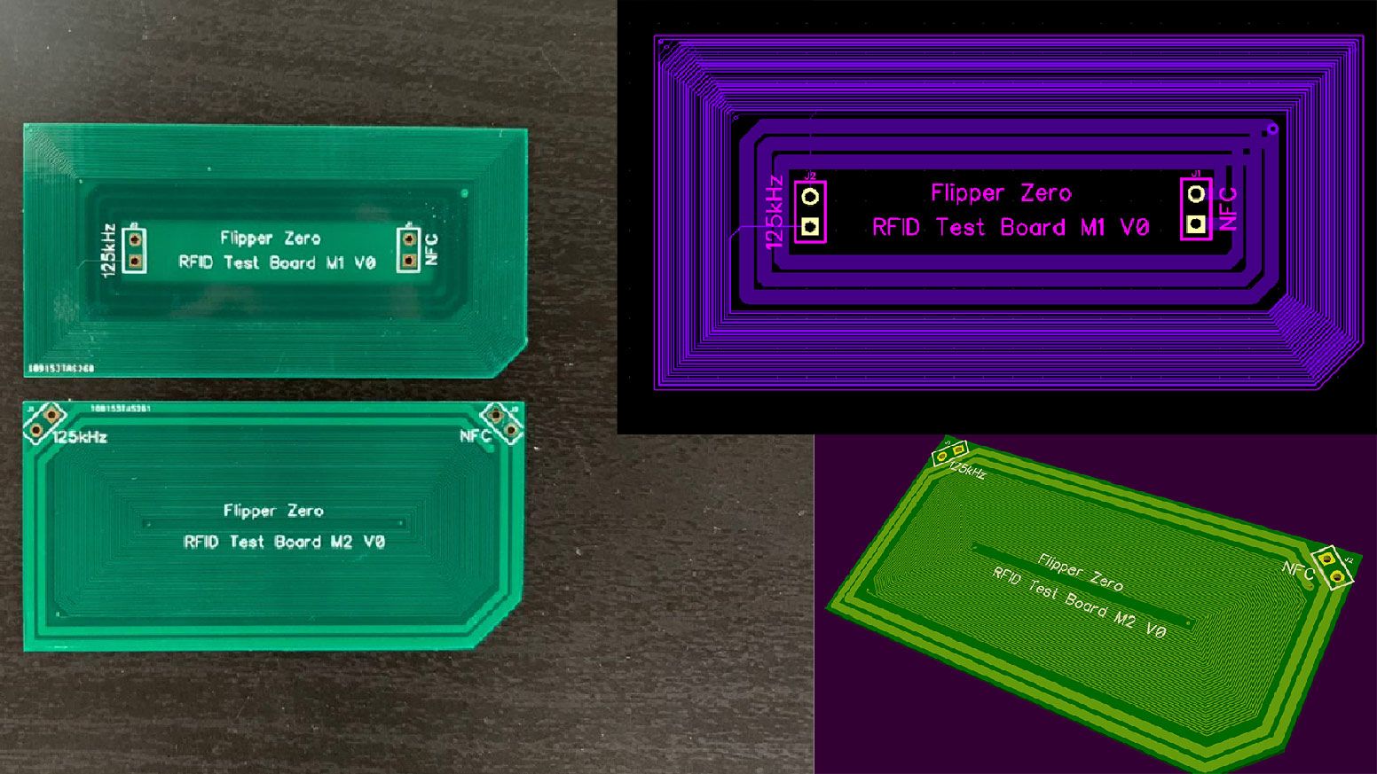
We tried several combinations, and in the end we found the best option, in which cards of different sizes in two ranges are readable. Flipper now consists of 4 boards inside.
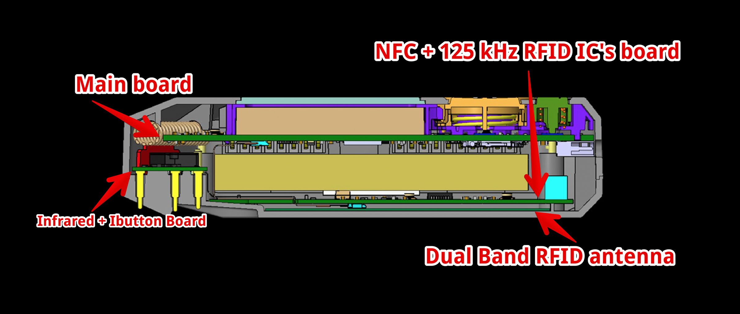 4 boards inside Flipper
MicroSD tests
In Flipper, the SD card works in SPI mode. This is a slower operating mode than the usual SDIO, but even in this mode the read speed is close to 400 KB / s, which is more than enough for our tasks.
 SD card read speed tests in SPI mode (bytes per second)
Answering the popular question “what is the maximum size of an SD card?”: We are now working with 16, 32 and 64GB cards without any problems. The FatFS library we are using allows us to work with maps up to several TB in size. The exFAT file system will be used by default. You can format the card directly in Flipper.
On previous prototypes, there was a problem when pulling out the card: sometimes the protrusion on the card touched the body. Therefore, we added an edge to the body, so the card is always removed without problems.
 Plastic rib fix SD card jam problem when pulling out
External GPIO changes
We had to use one GPIO on the Flipper for internal use, and we decided to connect pin 9 to the iButton pin on the bottom side. The same pin is responsible for the 1-Wire interface, so you can connect sensors and other peripherals using the built-in 1-Wire library.
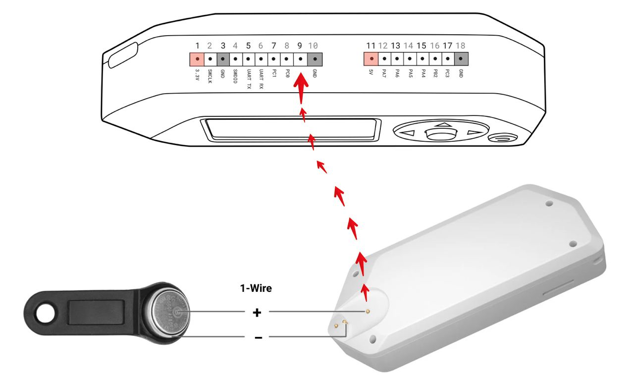 Pin 9 is now connected to the iButton pin (1-wire)
Interface
The first version of the main menu. Check out the animation of the icons. This is not the final version and the menu will be redone, but the general concept can already be understood
Demonstration of the main menu
Mechanics tests
Most of the work is spent on testing mechanical components. We constantly test different button designs, change springs and push rod designs. To do this, we print separate boards without electronics, only with soldered SMD buttons
Jokes
Our CTO Andrey @ coreglitch Strokov sometimes writes crazy things in Flipper, for example the floopper-bloopper game as part of the Ludum Dare 47 hackathon .
Another fun demo from our developer @ DrZlo13 old school music player playing the Wintergatan melody - Marble Machine .
Follow the development process and news about Flipper Zero in:
Blog in English
All Flipper Zero features on the official website .